
Category Archives: Arduino
I happened to stumble on an advertisement for a cool looking device that would work with a phone via Bluetooth. It was ideally something that would be used for things like movie times, bus waiting times, or something else small and URL based… kinda like a QR code without the annoying camera part.
So I got a pair of RFduinos to play with it. Programming it is quite simple, you just need Arduino 1.5 or later (which you would need for programming a Yun, Due, and possibly a few other Arduinos) and the RFduino libraries (see this). The library comes with an example program accessible under File-Examples-RFduinoBLE-AdvertisementContinuous.
The only somewhat difficult part is dealing with the URIBeacon, and Adafruit publishes a tool to help with that, and Google has a more detailed explanation.
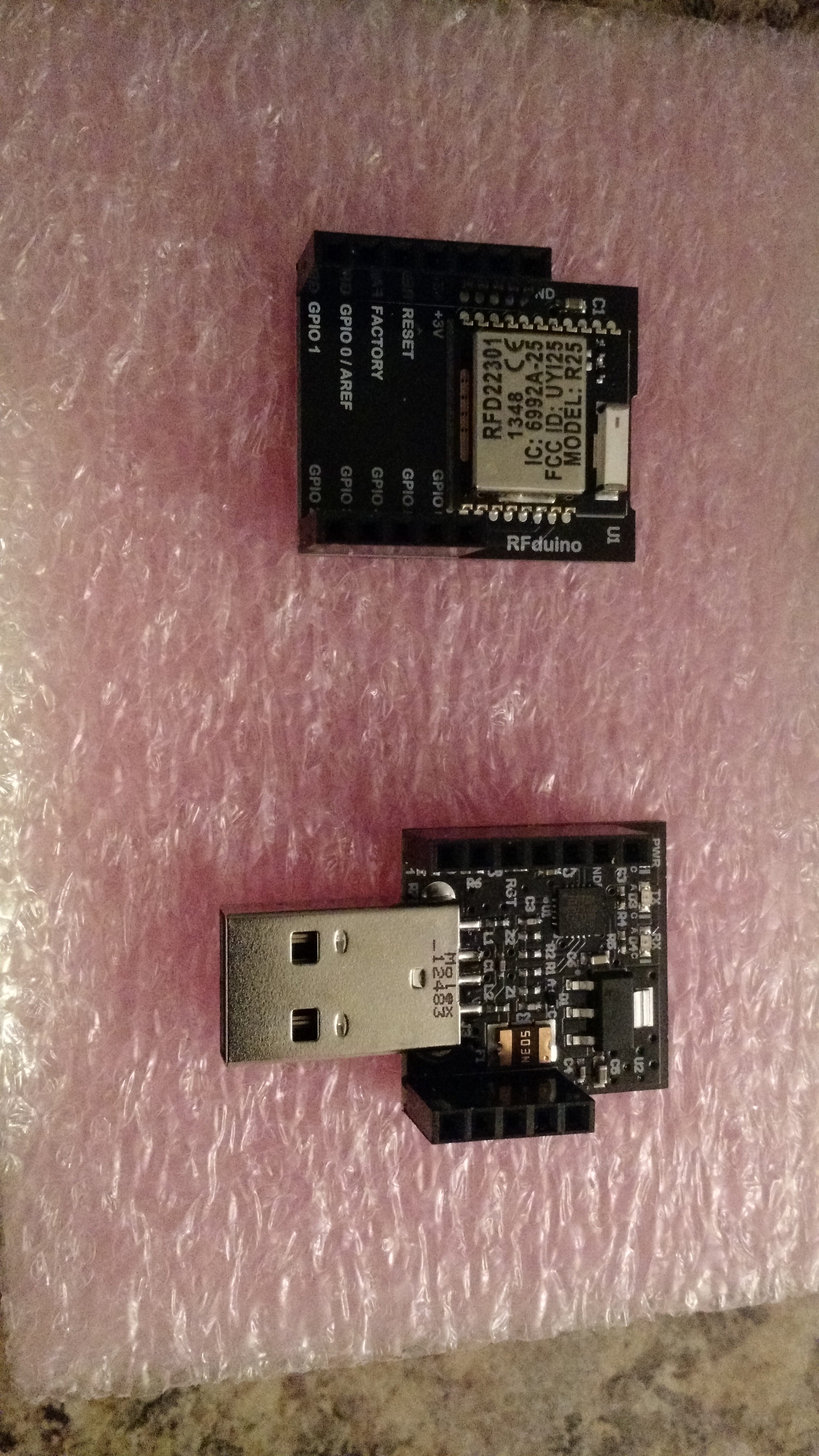
The top is the RFduino, the bottom is the USB shield, which is the easiest way to load it.
Of course it does nothing unless you have a device setup to receive it. In the Play Store, there is a Physical Web app that can be used to receive the messages (until these become part of Android… and hopefully iOS, too).
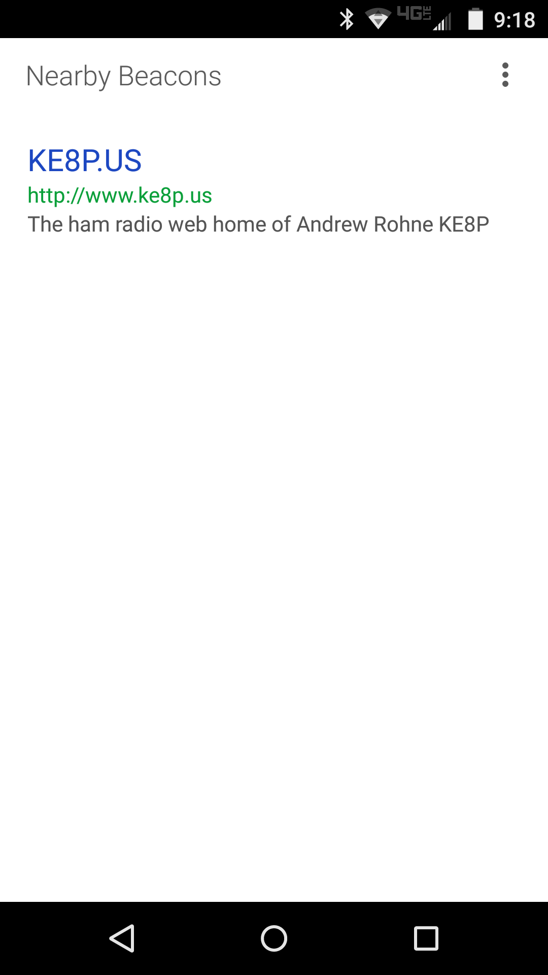
The app is fairly simple, but it works!
Where This Is Going
Rather than beacon a web URL, I imagine with the proper programming (on both the RFduino side and the Android app side), it could be used to pass a variety of messages. In fact, since the app looks up the description information, that could probably be used for simple messages (e.g. “the plant needs water”).
This has some pretty cool IoT and alerting uses. Stay tuned!
-73-
On the way back from a meeting, I dropped by the Columbus Micro Center Mall. I really didn’t know what I was looking for, but I figured I’d want to look at something for a project in the works (that involves an accelerometer or two), my Hack A Day Trinket Project, and anything else that looked good.
It was a good trip.
I grabbed a few (relatively expensive) breakouts for SOIC and SSOP chips, which I’ll ultimately use one for an SA602 mixer. I also grabbed a small pack of resistors, which will be in use for my HAD Trinket project. I found two accelerometers for $5 each (!!!). I grabbed a few PC boards. And the best part – a Yun for $55 (off their normal $75)!
I uploaded a microcontroller Hello World (a blinking LED) to the Yun via Wifi. It was awesome and convenient. The code is below, and it’ll work for any Arduino or clone (I initially wrote it for a Trinket).
In action on a Trinket:
And on a Yun (I used the onboard LED):
Next week, back to the normally scheduled DDS mischief.
-73-
A while back, I bought a few DDS modules through eBay. I used code from NR8O to program one of them and started pulling parts from the bin and pushing the output signal through the parts and into a load resistor.
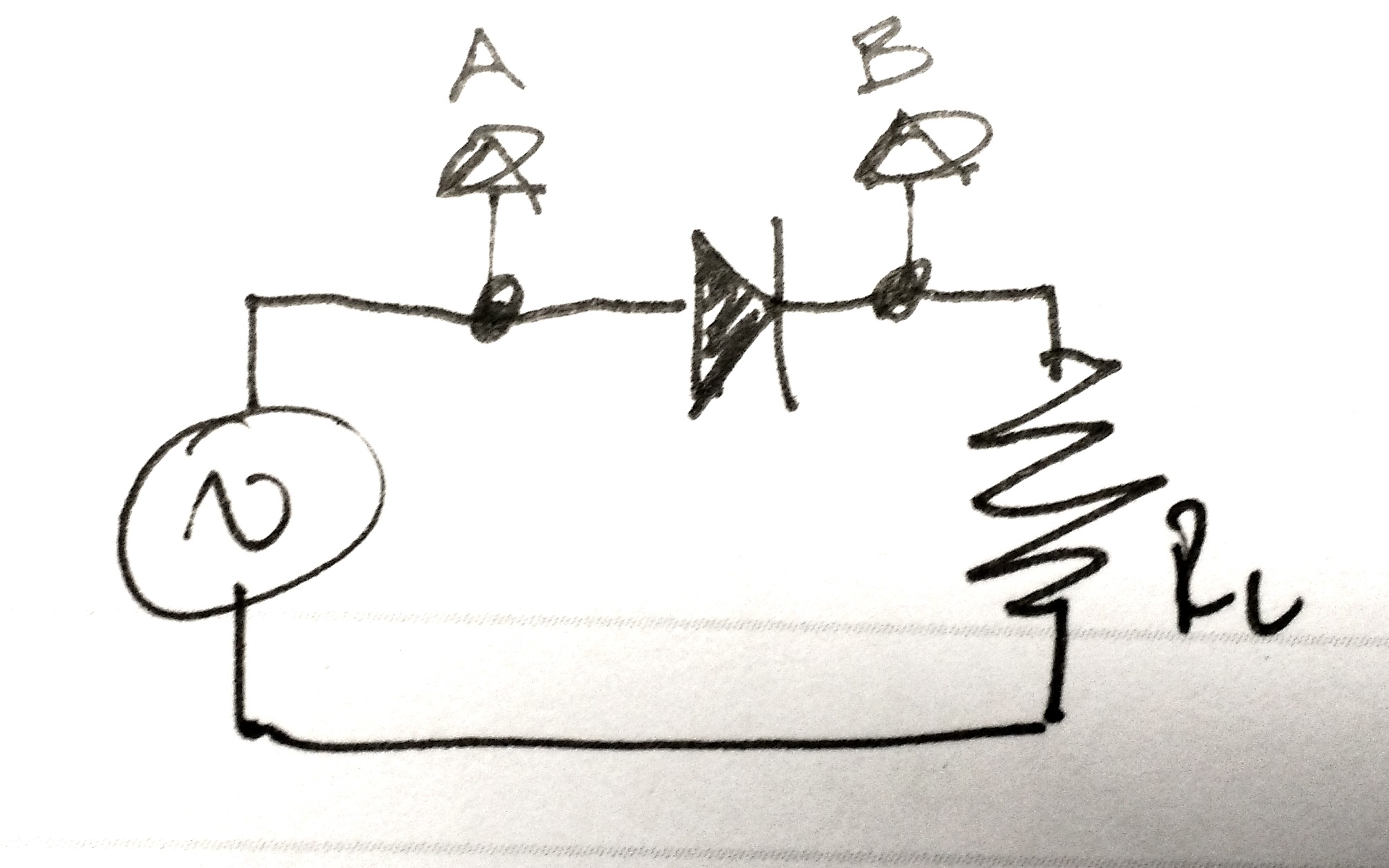
Experiment 1: Just a diode
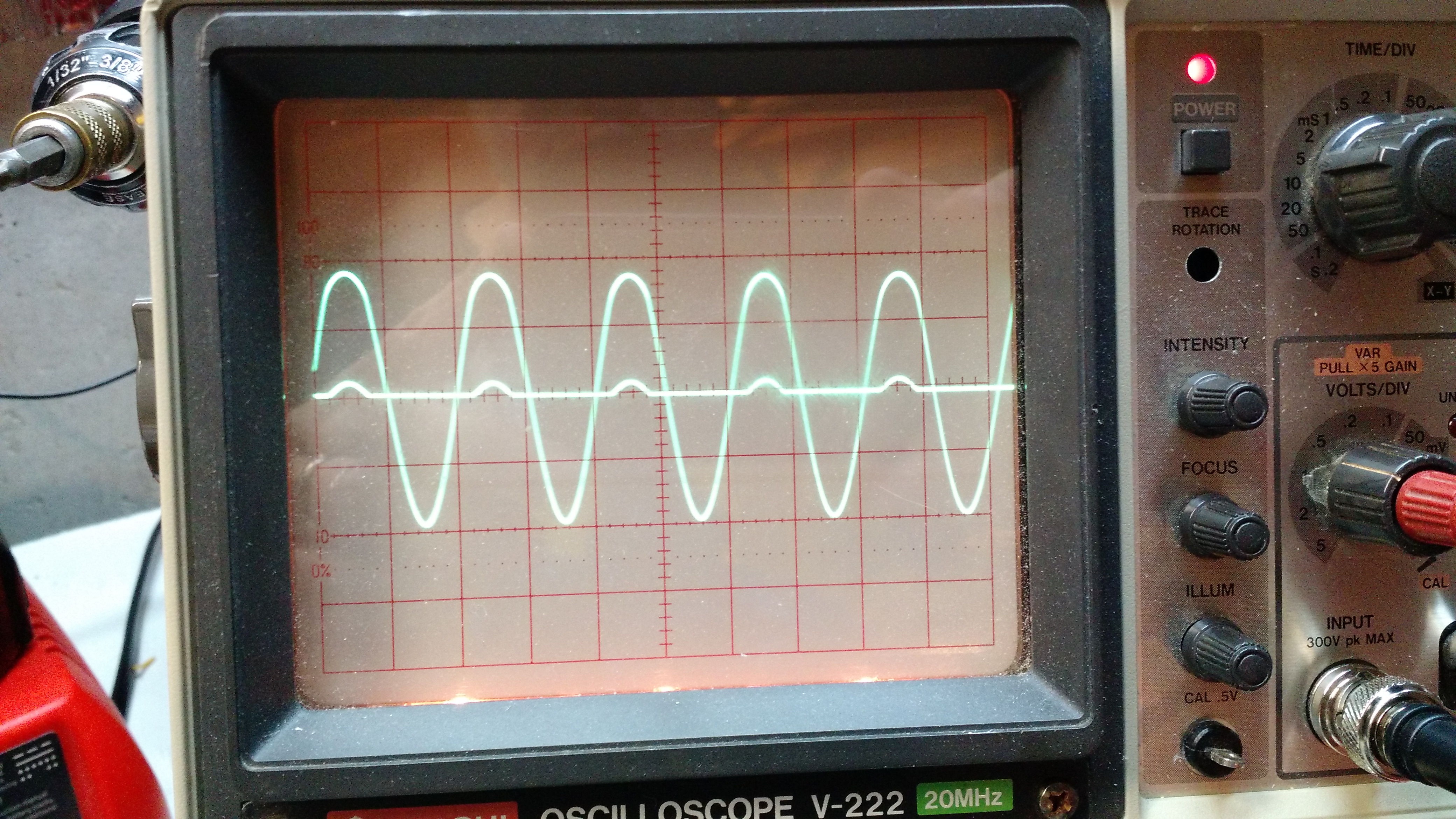
Result 1: the large waveform is the input signal (A), and the small bumps are the scope channel 2 (B). The diode rectifies the signal, which is why the bumps are only going up (and not down). The forward voltage drop on the diode is why the bumps are so small.

Experiment 2: a diode bridge
Result 2: This is similar to the circuit above, just more voltage drop because more diodes are involved.
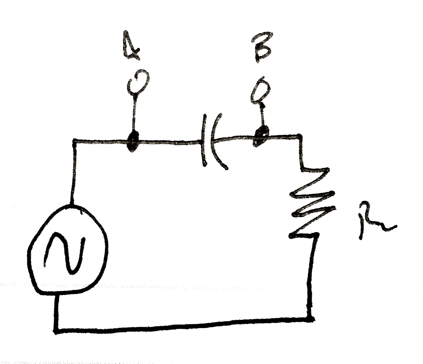
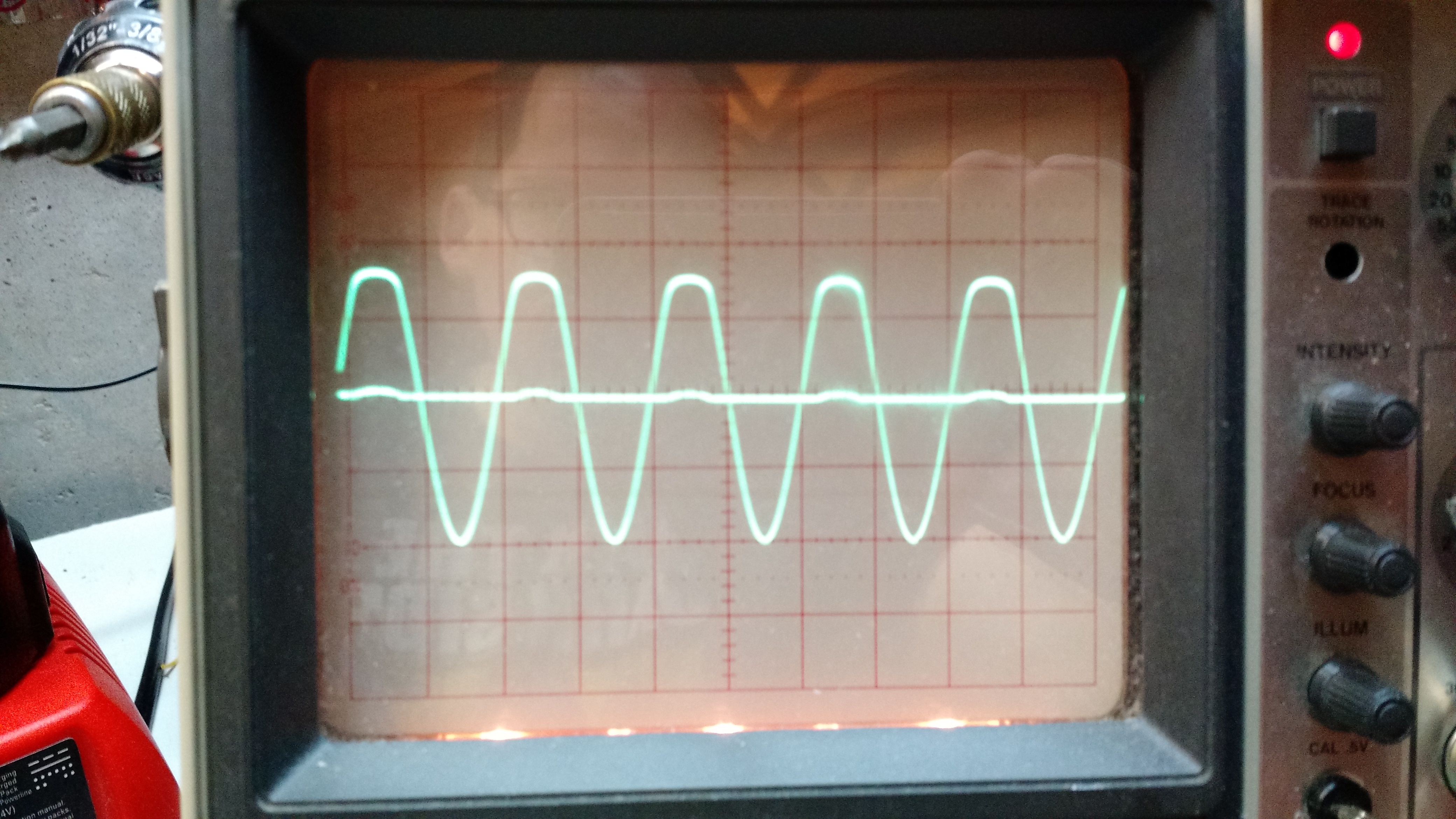
Experiment 3: Through a capacitor
Result 3: the capacitor blocks DC, but allows AC through, with some voltage drop.
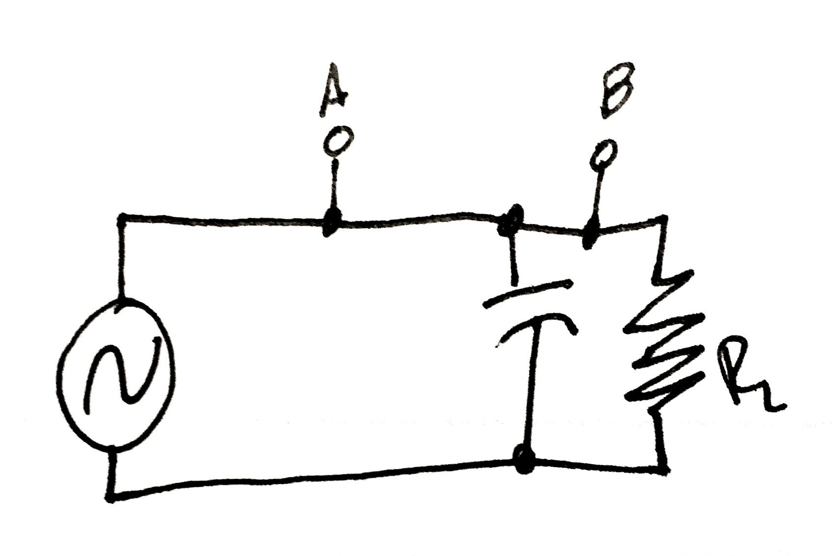
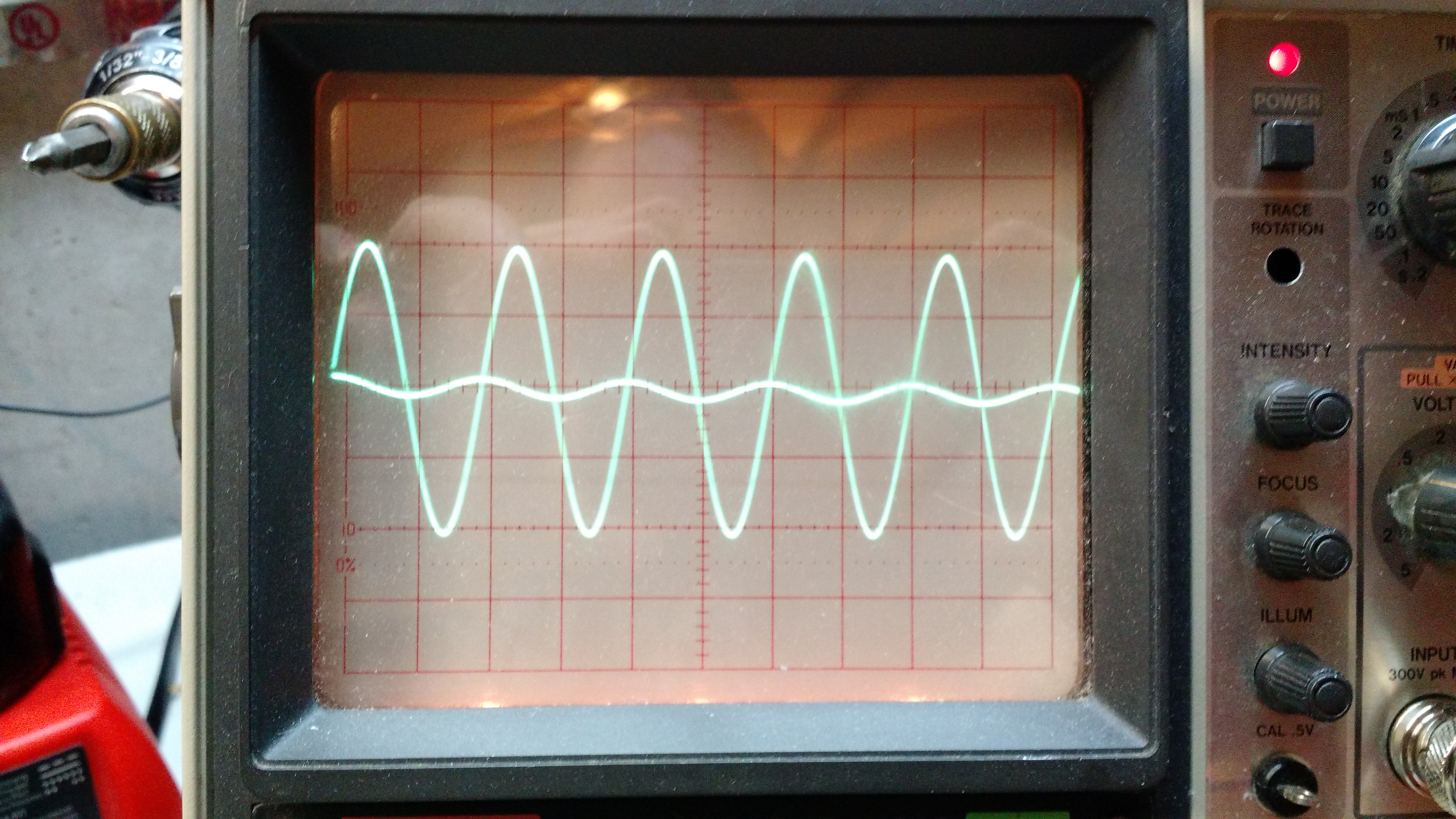
Experiment 4: Capacitor parallel with load.
Result 4. No change because there is nothing between the test points.
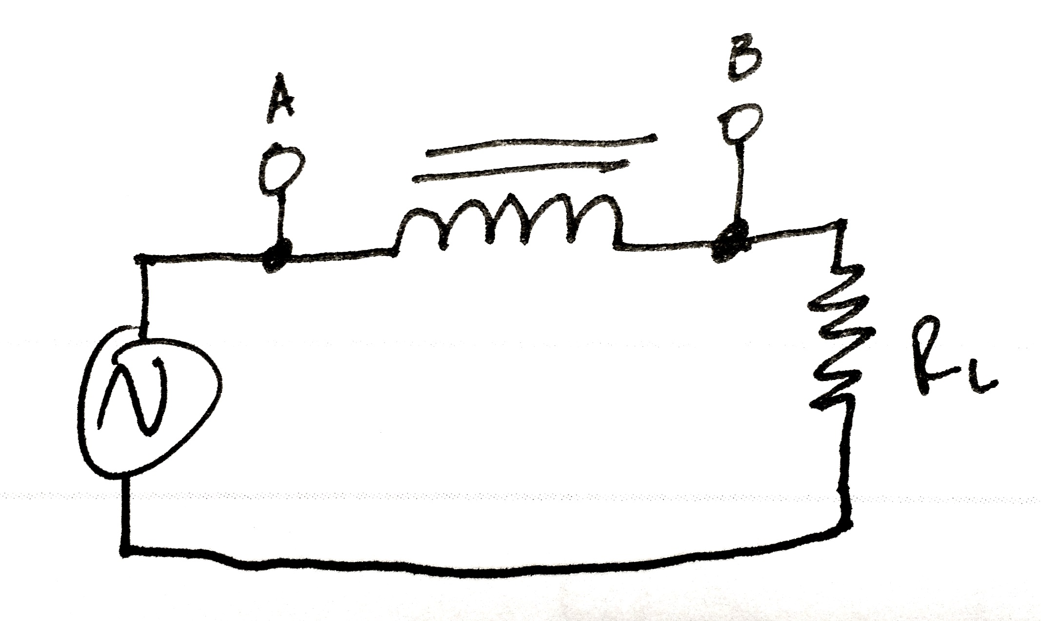
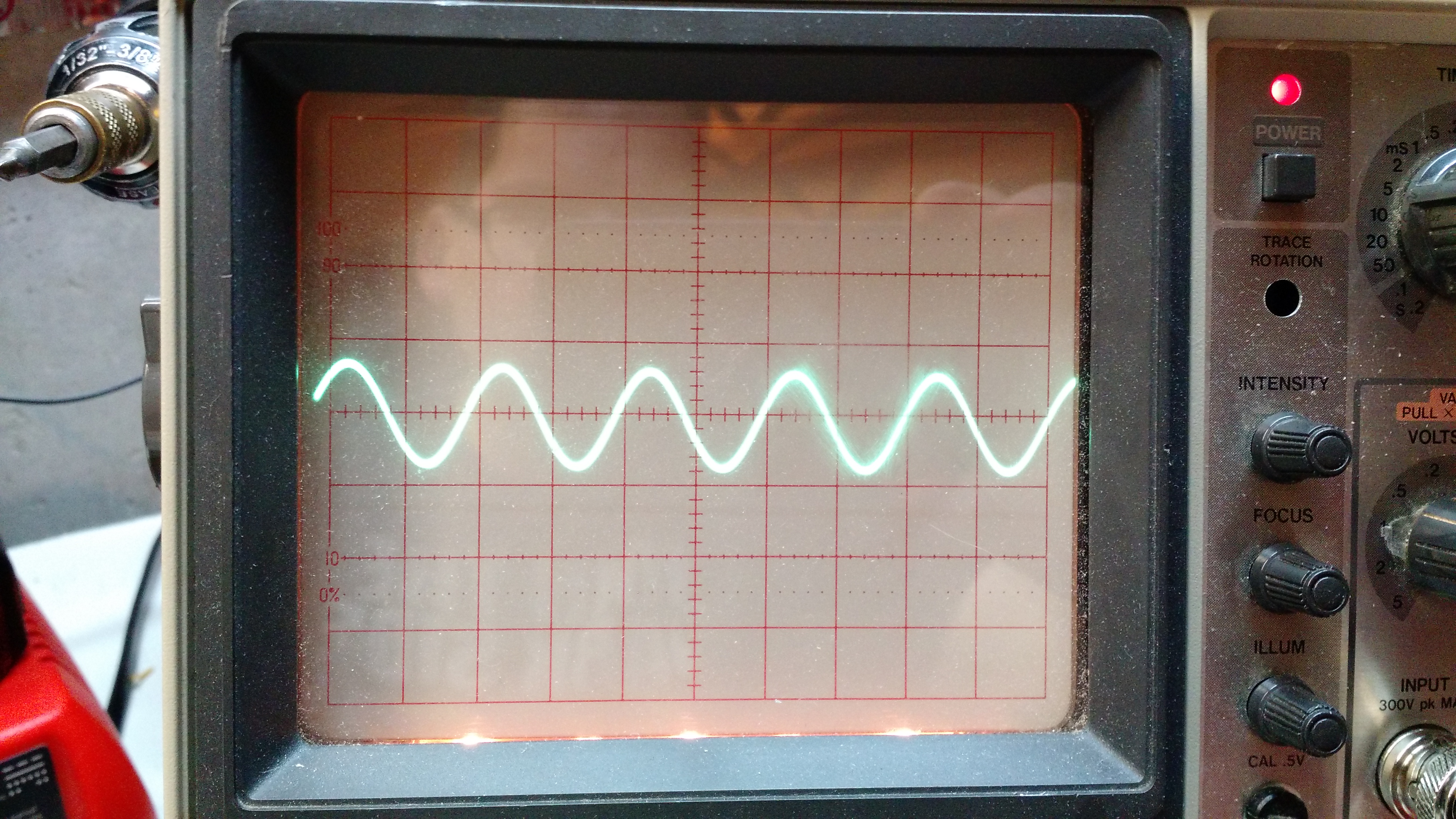
Experiment 5: through an inductor
Result 5: there was no change.
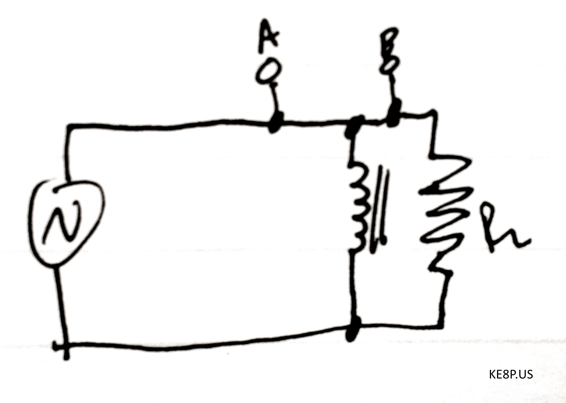
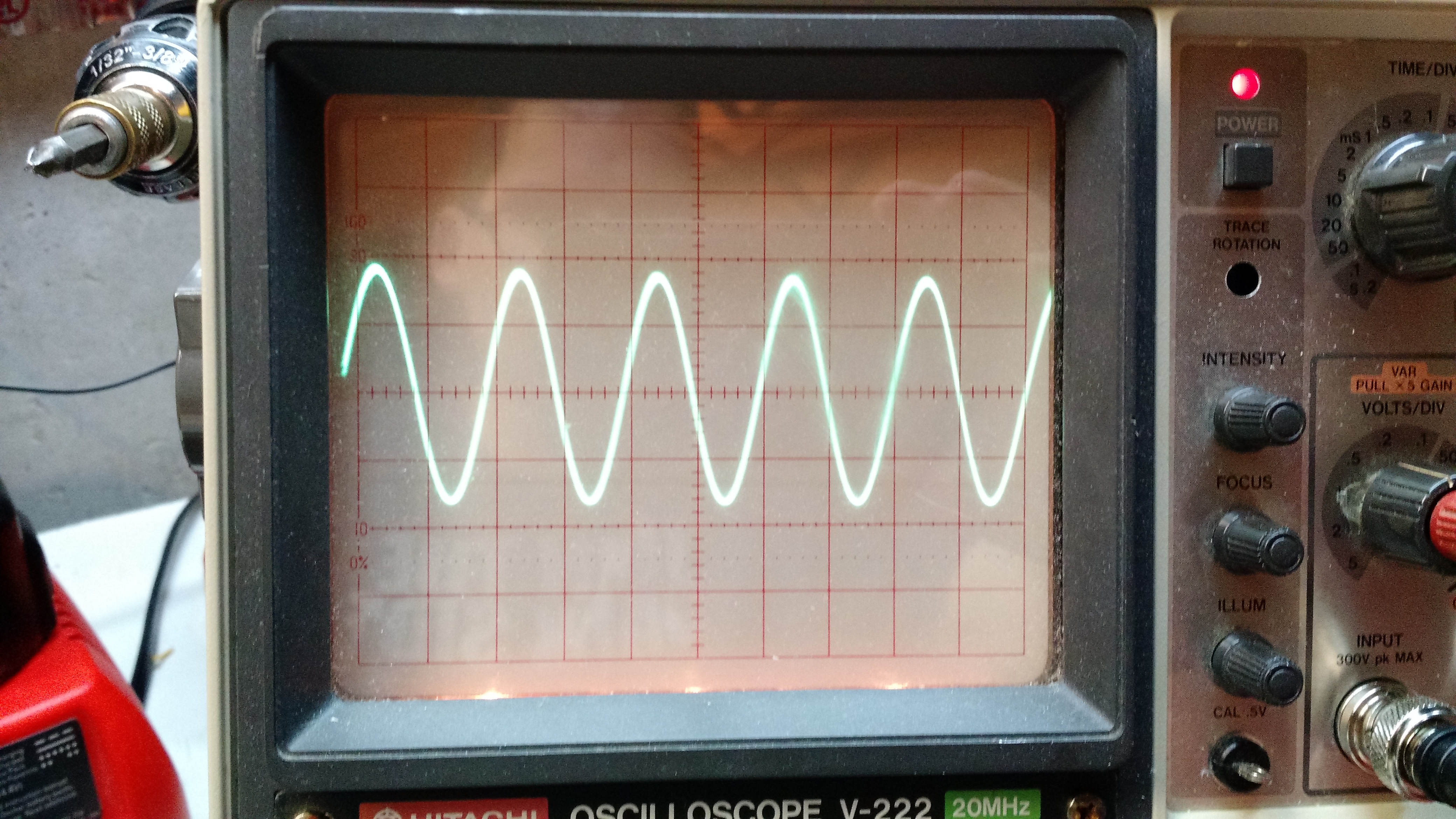
Experiment 6: inductive load
The video below shows what happened. I’m sure there’s an explanation of the instability, but I don’t know the explanation.
Stay tuned for experiments 2!
73 de KE8P
I bought an Arduino Due a while back, and not having anything seriously pressing, it was set aside for other things.
The Due has a lot of differences from other Arduinos for various reasons. The stuff you’ll see on most websites leads with “it’s 32 bits and runs at 3.3 volts!”. And those are important – any non-EE like me using an Arduino thinks at 5 volts, and in some cases you can blow up a Due with that much voltage. But there are more important differences:
- 4 serial connections
The Mega has 4 also, but the Uno and Leonardo have 1. Some things, like GPS receivers and the APRS Shield use serial connections, so this is a more-is-merrier situation. - 2 I2C channels broken out and labeled
All of the Arduinos have I2C interfaces, but they are not labeled on the Uno, Leonardo, and Mega. Really, this is just an inconvenience because you can look up the correct pins. The Due labels them so you don’t have to look them up, and the Due is the only current Arduino board that has two I2C interfaces.
I2C is useful for a lot of sensors, including temperature sensors, EEPROMs, real-time clocks, digital compass modules, and DACs. - 2 Digital-Analog Converters (DACs)
On the Uno, Leonardo, and Mega, there are no DAC converters – the analogWrite command writes to PWM outputs on those processors and that output is still 5V, but the output is a square wave that makes some things (like LEDs) look like you’ve reduced the voltage, when really you’ve reduced the amount of time that the voltage is on. Wikipedia has a longer explanation.
DAC converters do not output a PWM signal. Instead the actual voltage is output, so if you give a 3.3V DAC a command corresponding to 50%, it will output 1.65V DC (NOT PWM!). - Controller Area Network (CAN) breakouts
CAN is mostly used in vehicles in part of the On Board Diagnostics (OBD-II) system, but it is being adopted elsewhere. It’s adoption may continue with increased adoption of the Internet of Things. - Digital Signal Processing
Perhaps one of the more interesting parts of the board where amateur radio is concerned is that the main chip (where all the magic happens) is powerful enough (between being 32 bits and 84 MHz) that it can do Fast Fourier Transform operations as well as number crunching operations. Since there are both ADCs and DACs, an analog input can be sampled to digital data, processed, and then output through the DAC back to an analog waveform. See an example at M0XPD’s blog. This also enables the use of the Due as an SDR (another link to M0XPD’s blog).
I’m going to be doing a lot more here with the Due, so this should break me out of the no-post-slump I’ve been in.
-73-
Backstory:
I’m writing most of this as the ARRL June VHF contest is underway. With the 706 still laid up (parts did NOT come on Friday the 13th with a full moon… positive omen? No.), it’s on the bench gathering a little dust.
So I noticed in QST the August 70cm contest. I have 20′ (+/-) of masts, and 20 watts on 70 cm, and I can make an antenna… but I would need a good directional antenna because I have no interest in buying a 400 MHz linear amp for a contest that I may not have any contacts in.
“Good directional antenna” means a yagi or a quad. It also means it needs to be rotatable. I could just turn the entire mast, but I don’t know how that will work – my poles are fiberglass, and will have to be guyed, so that may be easier said than done. I have a junk box full of stepper motors, I have some Arduinos… this could get fun. Even better, it is temporary, so I don’t have to drop big bucks to do this.
So my thinking is that I want an inexpensive home-built rotator. I want the rotator to know where the antenna is pointing, and there are two components to this – a rotation sensor to tell me where the antenna is pointing and a sensor to act like a compass to tell me where north is.
All that being said, this is post 1 of 2.
Angular Sensors
For the hobbyist, there are basically four encoder options: optical, magnetic, capacitive, and mechanical. These can be incremental – where it tells you that there is change and how much the change is (or a pulse on change) or absolute (where it gives you a specific position).
Optical
Optical encoders are commonly found in printers and scanners, and the same concept was used by Ben Heckendorn on his Doggie Treat Dispenser. These have an optical sensor that looks for dark/light marks on a disk on a rotating shaft. I don’t know about prices for these, since I have a few of them from a coworker’s printer that stopped working.
Magnetic
Magnetic encoders operate by using a magnet and a hall effect sensor to sense the change in the magnetic field due to the magnet’s rotation. I’m guessing (operative word!) that these are bad to use in strong magnetic fields (like near a motor, hard drive, or one of those big electromagnets used in junkyards to lift cars).
It appears the only magnetic encoders available (for hobbyists) are analog – they give a voltage output based on the rotational position. This has the benefit of being absolute or semi-absolute. Prices range from $10 to $45 from the big US suppliers. Their use with an Arduino would be similar to the use of a light sensor (although the voltage divider may be built into the sensor, so you may not need to have one separate).
Capacitive
Capacitive encoders work similarly to optical encoders, but instead of using a beam of light, it uses a set of disks and a capacitance sensor. Benefits (according to CUI) are that dust can mess up optical encoders and that LEDs can burn out.
Capacitive rotary encoders run around $25 and provide up to 2,048 positions of output (that’s one every .18 degrees!). Looking at the linked item, it seems to be the most ready-to-use sensor, depending on the application.
Mechanical
Mechanical rotary encoders are common in selector switches. They have mechanical rings inside (I couldn’t find a good explanation of how this works). They are inexpensive and common, but I’m not sure of their use within an antenna rotator. Truthfully, the amount of torque needed to turn a selector switch is so much that I’m not sure this is really an option.
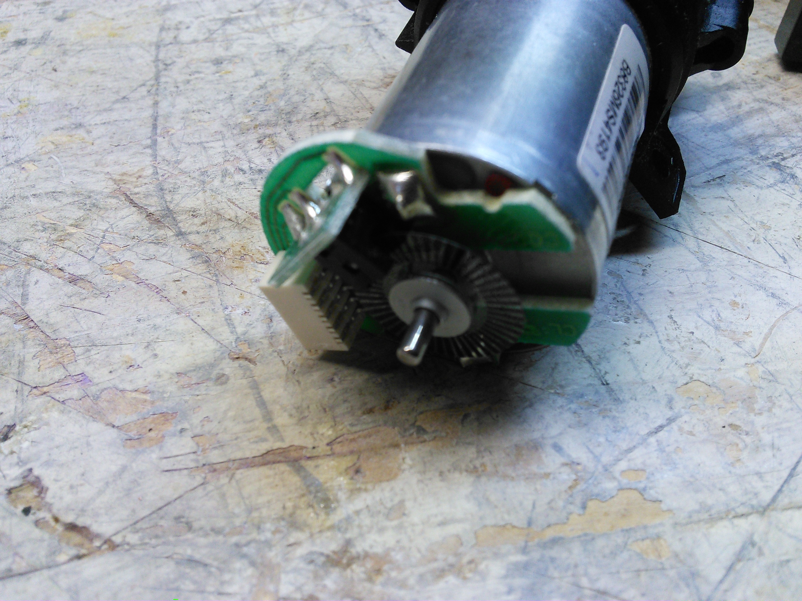
Next Step
As the only picture on this post indicates, I have a motor with a sensor. I am going to build that into some sort of rotator that can be mounted on top of a fiberglass pole that I can use to turn the antenna. I don’t know if I can have it done by August, but I’m going to try… presuming I get the 706 fixed first!
Last week (on a post that proved that even an evil genius can sometimes mess up simple math and set a post to fire 4 days early) was the introduction, today is some new findings.
Memory
If you follow the directions and treat this like an “Arduino Pro or Pro Mini (3.3 v, 8 MHz) w/ATMega 328”, the Arduino compiler will tell you that there is a 30,780 byte maximum. In my experience, the maximum is around 26,000 bytes. Wyolum knew about this, and this is why they included a micro-SD card slot and card. At one point, I tried creating a program that would tell the temperature and lines from the Zero Wing intro (“All Your Base Are Belong To Us!”). It didn’t go well.
Temperature Sensing
The temperature sensor is very simple to use. Recall in the last post, the sensor itself is populated, but a 0.1 uF capacitor (C8) is not. The sensor might work without the capacitor, but it likely works better with it (at least I hope so, I populated the cap without testing and I have zero interest in removing it).
To read the analog pin and get it to a voltage, the following code works for me:
int ar=analogRead(7);

float vref=3.3;

float temp=ar*vref/1024.0;
Even though the Pro and Mini do not have 7 analog pins, the Arduino IDE and compiler not only do not complain about not having the pin, they compile it correctly without modifying any of the libraries (Good on ya, Arduino!).
Looking at the data sheet, there is a simple equation for the temperature:
$$V_{out}=T_{C}*T_{A}+V_{0}$$
Where:
$$V_{out}$$ is the output voltage
$$T_{C}$$ is the temperature coefficient
$$T_{A}$$ is the Ambient Temperature
$$V_{0}$$ is the voltage at 0°C
Per the documentation, I used $$V_{0}=0.5v$$ and $$T_{C}=0.01V/°C$$. Using algebra (who says you’ll never need it?), I used:
$$T_{A}=\frac{V_{out}-V_{0}}{T_{C}}$$
Which would give me the temperature in Centigrade, and after that,
$$T_{F}=\frac{9*T_{C}}{5}+32$$
In Arduino, that wen’t like this:
temp=temp-0.5;

temp=temp/0.01;

// C to F

temp=(9*temp)/5+32;
And it seemed to work correctly. I was getting temperature readings of around 74 in my office, and it seems like that is correct. The final code is below.
…and of course, I can’t show all this code without the finished product:
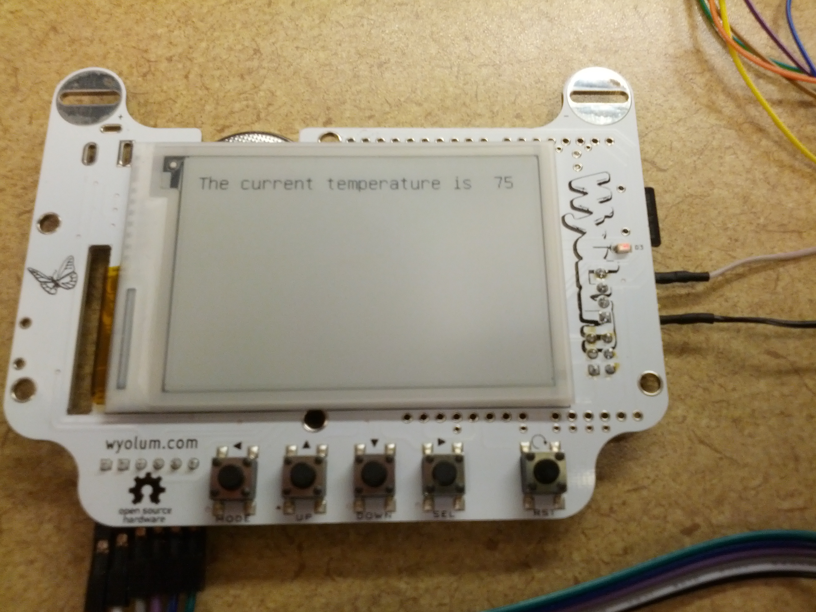
It’s a warm 75 in here today… and it does feel kinda warm in my office.
By the time this post fires, I will have just returned from a transportation conference. I hoped initially that I’d have more with this post, but it’ll have to wait for next week’s post.
-73-
Ever since seeing the name badges from the Open Hardware Summit 2013, I wanted one. I tend to make it to 2-4 transportation conferences a year, plus 3-5 hamfests, so having a cool looking badge is… well, just a want.
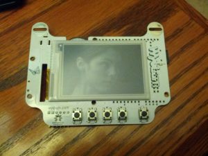
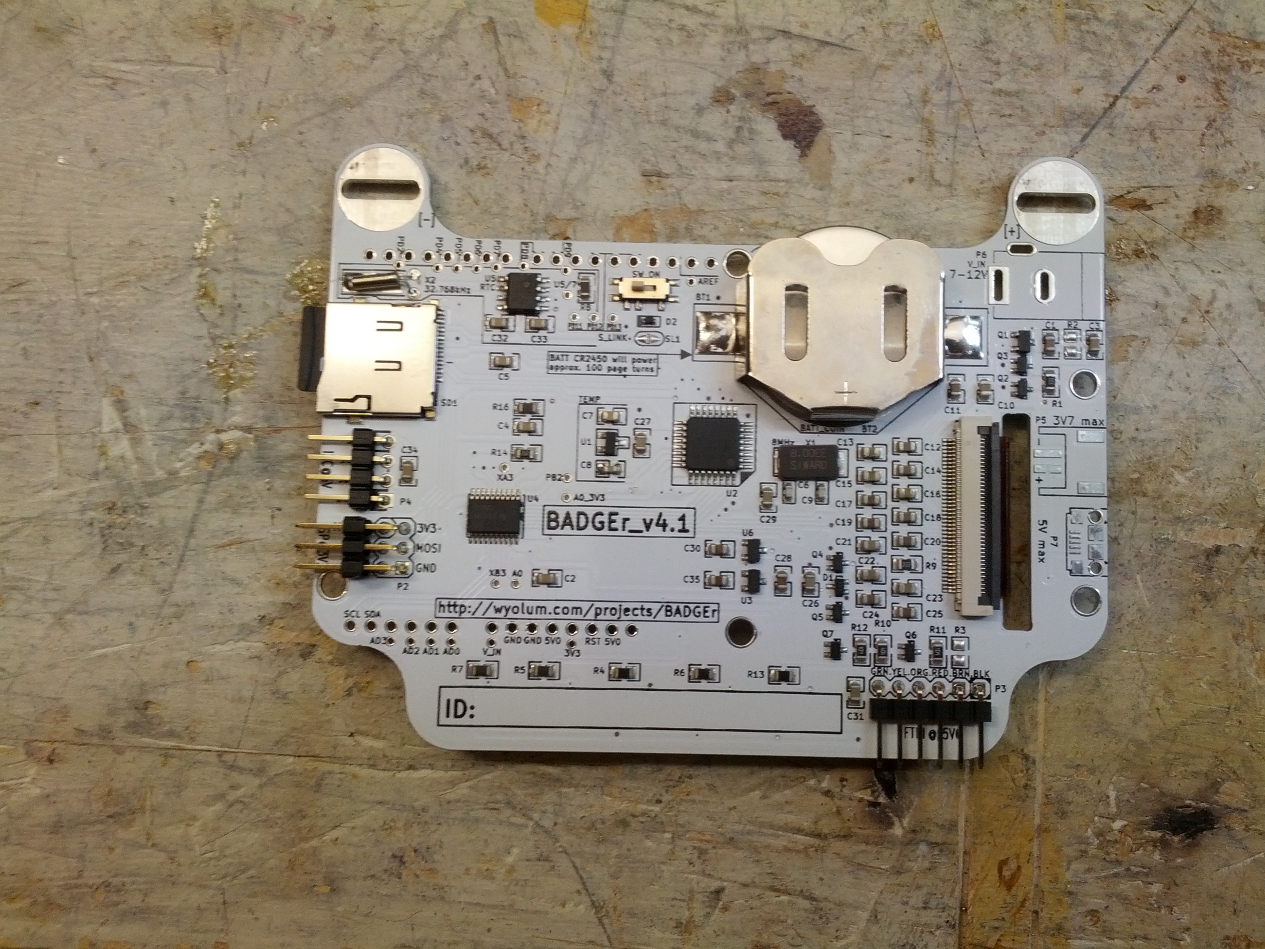
The front. Five buttons and an e-ink screen.
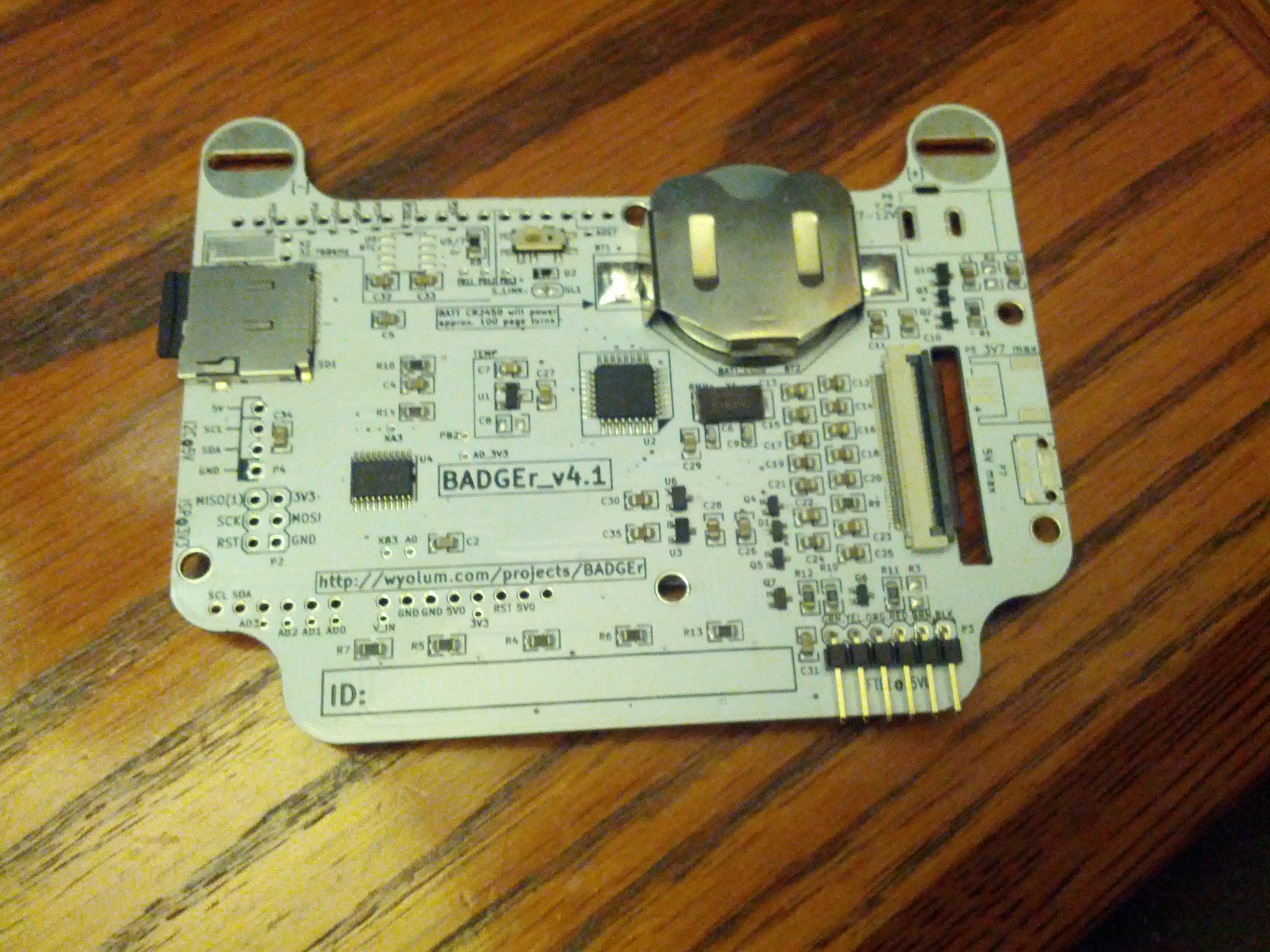
The back. Coin cell, on-off switch, microSD card, serial headers, and components.
First off, the e-ink screen idea is pretty awesome. It maintains an image with the power off, which is a great feature (especially since there are only around 100 page turns on that coin cell).
The powerplant of this is an Atmega 328p. The same Atmel processor used in the Uno, Pro, Nano, Fio, and some Lilypads.
Per the website, there are two unpopulated items – a realtime clock and a temperature sensor. However, looking at the schematic and the board, I see the unpopulated realtime clock area in the upper left area of the board, but in looking just to the left of the 328, there is a temperature sensor – the only unpopulated area is for a 0.1 uF capacitor!
I didn’t even program the thing before fixing those little omissions. I had to make a little change to the realtime clock I had is an NXP, and the doc calls for a TI chip. The only difference – pin #3 is a backup power input on the TI chip, and on the NXP chip it is an interrupt output. I clipped the pin prior to soldering. I also soldered the ICSP and I2C connections, since I think I may end up using those at some point.
The first thing I did with the BADGEr is get a copy of the firmware that is on it. After trying to use avrdude with an FTDI board, I did what I should have done the first time – used the Bus Pirate. Using the connection instructions on Dangerous Prototypes’ website, I used the following avrdude command:
avrdude -c buspirate -C”..\etc\avrdude.conf” -P COM9 -p m328p -U flash:r:”C:/badgr.bin”:r -b115200
** CASE SENSITIVE **
The -c option tells avrdude what programmer avrdude is using.
The -C option tells avrdude the configuration file. In my case, I’m running this from somewhere down in the Arduino IDE folder, and relatively speaking, backup one and then into the etc folder.
The -P option is the port number (in my case, COM9)
The -p option is the part number, in the case of the BADGEr, it is an ATMega 328p and per this page, that is the correct string to use.
-U is the operation. ‘flash’ is the part of memory to work with, r means to read, the next part is (obviously) the file path, and the final r is for ‘raw binary’.
-b115200 is the connection speed. My Bus Pirate is setup for 115200 bps, so I used this. It will not work if incorrect.
Once I ran this (well, twice because I forgot the final r option in the -U portion), I got a raw file with the code on the device.
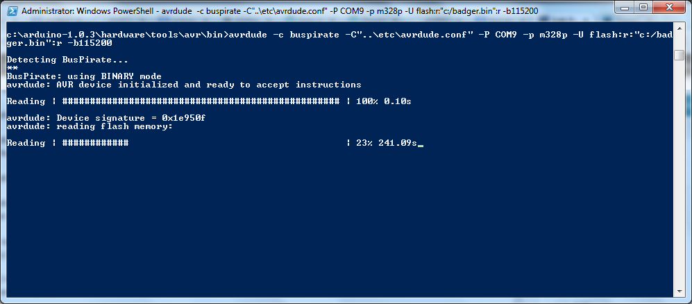
It takes a while…
It took 1,048 seconds, or about 17.5 minutes. For a 32 KB file. There’s some fixes for that HERE. Use them well.
Initial Programming Experience
After screwing around for several days trying to load the BADGEr from SPI, I fixed one of my FTDI boards and got it to work. My advice here: don’t even mess with trying to load sketches via the SPI interface. It won’t work (and I’m not sure that was ever intended).
Initial Program
Thoughts
The battery included died very quickly. I think my next improvement will be a better battery! This DOES need a good power source when programming. I initially used my Bus Pirate to power it while programming it from the FTDI cable.
-73-
Yes, I shouted that. And for very good reason – Arduino started me down the road of playing with micro-controllers (you can tell I haven’t made a red cent on any of this – I call it “playing” :-)). I guess you could consider Arduinos to be my gateway drug into Raspberry Pis, Beaglebones, and PICs.
In celebration of Arduino Day, I decided that I should list a few of my favorite Arduino Projects (some are still in progress).
This is probably the coolest thing I started to write. It is also the most useful, as it would have it’s uses with any receiver setup, whether it is a home-built radio, an RTL-SDR, or even an off-the-shelf radio).
I didn’t do very much with this, and what I really learned wasn’t even discussed in the post- I really learned how to ‘break out’ of the Arduino IDE and load an Arduino from the command line. With Linux.
The Arduino Easy Logger Button
This is the start of what ended up netting me a ChipKit WF32. I want (and still need to finish) a setup that makes it easy to log my radio contacts while mobile. The Arduino version is around 90% done, but with several things taking my time it hasn’t been finished. And the ChipKit version has got a longer road.
-…-
I thought I’d have more of these, but I guess I don’t. I do have a few “in the queue”, though, so hopefully when I write some for AD15, I’ll have a few more. Either way, I’ve learned A LOT and I know I have several more posts coming that use my Mega 2560 and Due (and maybe even that Leonardo I picked up a few weeks ago).
-73-
I’m not going to call it a spectrum analyzer anymore – the way I’ve designed this, it isn’t going to do the same things as a spectrum analyzer.
The main difference is that a spectrum analyzer can operate without a signal generator, this won’t because the signal generator is what is going to tell the Arduino what the frequency is.
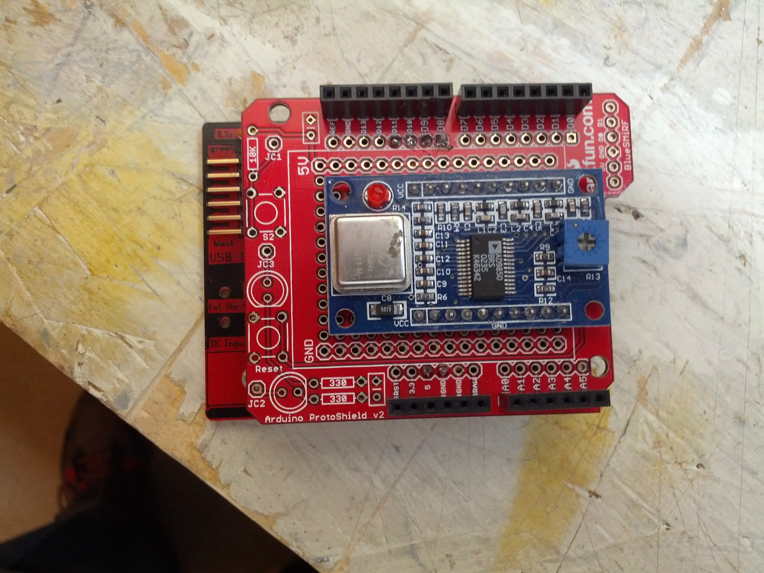
I built another shield to stack onto the shield in last week’s post.

There is currently no connection from the DDS to this yet, but that’s one of the only few things left to do on the hardware side.
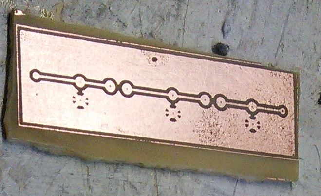
I also built a filter that will ultimately be the first filter to test. This is for my Softrock 20/30/40 and should pass 7 MHz while filtering 14 MHz.

This will fit in a Radio Shack small plastic enclosure – the plate was leftover from a small dummy load that I glued into the enclosure.
-73-
I’ve been reading a lot about receivers, and it sounds like one important thing is filtering. It makes sense too – simple receivers can suffer from front end overload due to a strong signal. And when on the ham bands, you never know where that strong signal may be – it could be someone driving down the road (which is a bit obvious once you see it), but in my neighborhood, if you don’t know me, you’re probably not going to know about the antennas in my attic.
I don’t have a spectrum analyzer, and since I’m a traffic engineer, I really don’t have access to one. I don’t need a full-blown spectrum analyzer, either, I just need to sweep through the HF band and get the difference between signal input and output. Math will take care of the rest.
$$dB=20*\log{\frac{V_{out}}{V_{in}}$$
The way I figure it is this:
An Arduino (and this could become a Raspberry Pi or any number of other devices, but I’m going to use an Arduino because it’s cheap and relatively durable) controls a direct digital synthesizer (DDS) module that just scans through it’s limits… well, probably something like 0.5 MHz – 40 MHz – that gets me into the AM broadcast band (which can be a source of strong signals) to above the 10m band (I don’t know what’s up there, but whatever’s there is probably not running 50,000 watts).
The output of the DDS would have an RF voltmeter and a probe to go to a filter. There would be another RF voltmeter to sense a filter output. The Arduino would handle not only control, of the DDS, but also sensing the voltage.
It’ll look something like this:
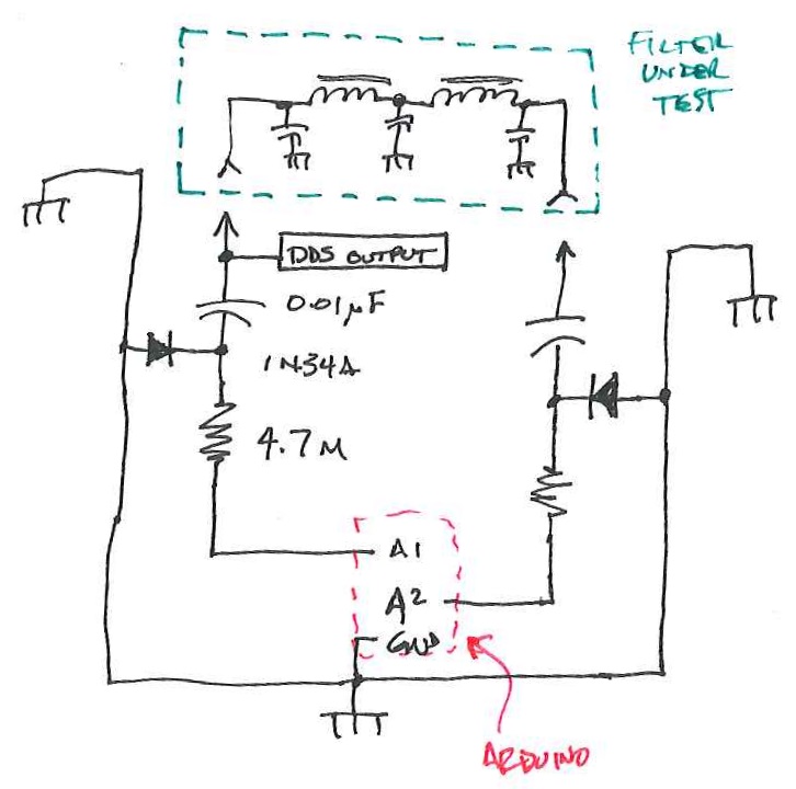
This is a block diagram/schematic of how this will work. I didn’t include the DDS module, which would be tied in there somewhere.
The Arduino and DDS will look like this:
There will have to be a companion app to this. In Java (not just because I’m drinking coffee, but also because it’s cross-platform). It’ll look like this:
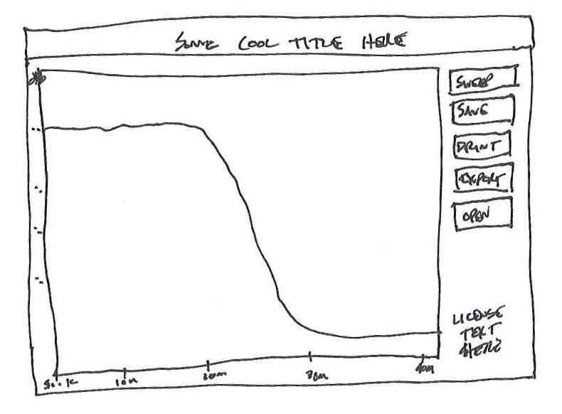
This is likely how things would look. Simple. A button that tells the Arduino to sweep, and some other important buttons.
I have the perfect item to test with also. One thing I built and don’t use (and never truly finished) was my Softrock RXTX. I need to build a filter for the output to keep the harmonic of the 7 Mhz fundamental from being too strong on the 20 meter band. I wound the coils while watching the Super Bowl-over-the-Broncos and printed a circuit board just before the game started.
Easy and small, but for 0.95 Watts, you don’t really need much.
I’m not really sure if this will work, but it certainly seems like it would, and I think it would be interesting to see how some filters respond on this compared to a real spectrum analyzer.
-73-