
Category Archives: Electronics
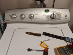
My GE Profile (I think… model WPRE8150H1WT) washer decided to stop spinning out the load. Otherwise, it would work correctly. After checking for obvious stuff (unbalanced/heavy load, pump failure, etc), I looked into it and ultimately fixed it for free.
Troubleshooting Steps
Obviously, with some of the below steps, checking after is necessary.
- Unplug the Washer for a Minute
This is effectively a reboot. It has a microcontroller or something on it to tell it what to do, and the first step is to reboot. - Reset the Motor Controller
According to GE on YouTube, you can reset the motor controller by doing a reboot (unplug for a minute) and then open/close the lid 6 times in 30 seconds. - Check the Motor
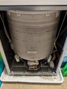
The motor is front-center-low on the washer. You can remove the front panel by using a putty knife to disengage some clips at the top and it tilts out. The motor has a light on it that should be flashing in a regular pattern. If it is not, it will blink a pattern and repeat it every six seconds. Check the service manual (do a web search for it) for what the pattern means. - Enter Field Service Mode to Check Things
This is done by holding down the button and turning the mode switch half a turn (don’t go too fast, it needs to register each click) and releasing the button. You did it correctly if the display goes to 88 with all mode LEDs lit on the time-remaining display.
Turn the switch clockwise one position, it should go to a model code. The following position is a diagnostics position. Mine showed something interesting here related to a slow pump fault. According to the service manual, this can be due to the pressure switch not resetting.
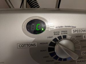
Turn the switch a few more positions, and H or C should display on the display. This SHOULD activate the hot or cold valve (as appropriate) UNLESS the Rinse LED is on (see the image below), which indicates that the tub is full. In my case, there was no water in the tub. - Use Field Service Mode to Test The Motor and Mode Shifter
Since my washer wasn’t spinning, I turned the dial to P to activate the pump (it works!), then to SP for spin (for several minutes), and then to AL and AH each for a few minutes. Since it began to spin on spin and agitate on the AL and AH modes, I decided that the motor and mode shifter (like a transmission) were probably not the problem. I also lifted the lid while the tub was in spin mode, which activates the brake – it stopped well short of seven seconds (the standard used in the service manual).
Resolution
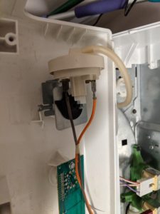
Since signs were pointing to the float switch, I removed the front control panel (four 1/4″ bolts on the back, tilt forward, and then slide the panel to the right) and test the switch. The switch should be normally-closed. My tester indicated it was open. Prior to buying a $30 switch, I removed the tube and blew into it – something was in the tube blocking it making the unit think there was water in the tub when there wasn’t. I tested the switch again, which was now closed. I reassembled the washer and tested the spin cycle that now works.
Conclusion
Troubleshooting is pretty important – in this case, not only did I save money and time by fixing my washer (a new comparable washer is around $600), but even if I replaced the pressure switch it wouldn’t have fixed the problem because the problem was in the tube.
Prevention is pretty important, too. Many people (including me) do not clean washers. I guess we assume that since it looks clean inside that it is. Occasionally, we should run a large load of hot water (only) with some Oxyclean to clean it out. I’m not sure if that would have prevented this, but there’s a chance it would have.
Part of my real job is traffic counts, and I’ve been working on some permanent traffic counter setups. The counters that we are using have an RS-232 interface, although in certain situations, an RS-485 connection must be used.
They don’t make computers with RS-485 connectors on them (anymore). So I’ve purchased an adapter, and then a coworker purchased another (more expensive) adapter. The differences are interesting.
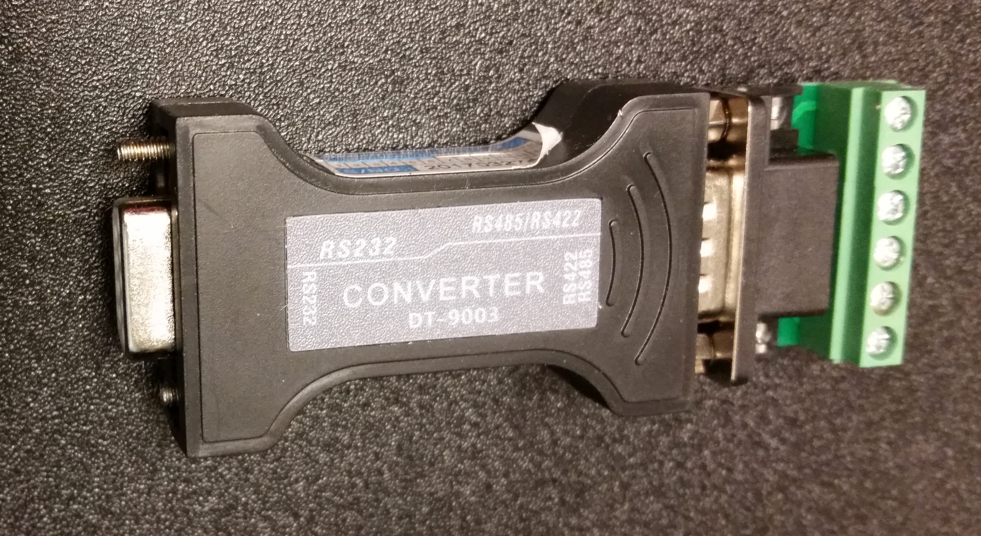
Adapter #1
Adapter #1 is an inexpensive $10 on Amazon (affiliate link). I’m not going to post an image of the inside, but there are 4 chips:
- an ME7660C Charge Pump (converts +5V to -5V)
- A 4093 Schmidt Trigger
- Two SP485EE RS-485 Interface chips
The reason for two RS-485 Interface ICs is because RS-485 is full-duplex, so my guess (without tracing the circuit board) is that one chip handles the positive RX/TX and the other handles the negative RX/TX.
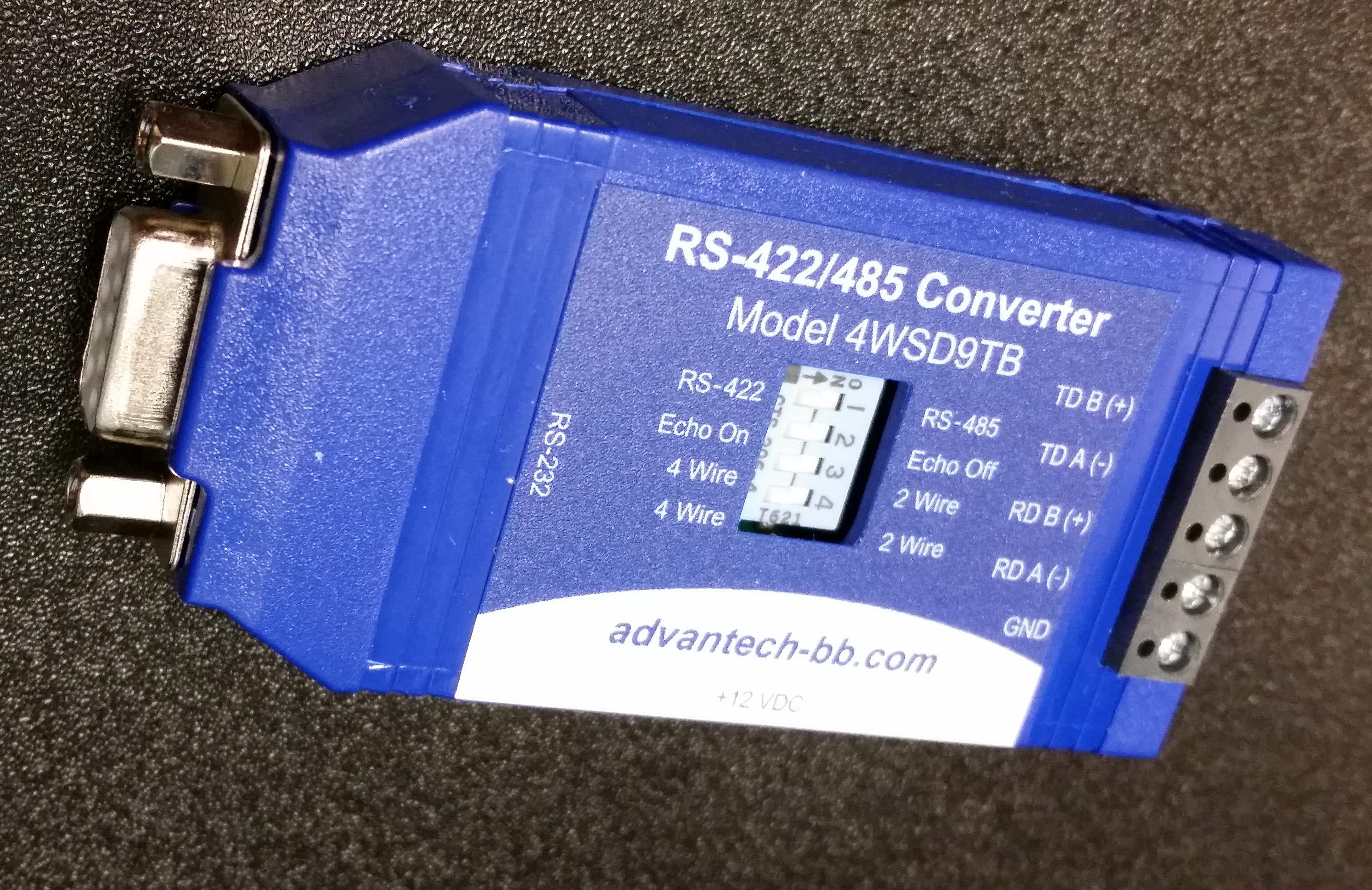
Adapter #2
Adapter #2 is a far more expensive converter (it’s $80 on Amazon, affiliate link). Similar to above, I’m not going to post an image of the inside, but it also has 4 chips… some similar, some not so much:
- 7660C Charge Pump
- MC14093 Schmidt Trigger
- SP3220 RS-232 Transciever
- SP485EEW Full Duplex RS-485 Interface
This particular adapter was recommended by the manufacturer of the traffic counters we are using, and my thought is that it has to do with the fact that it has a full-duplex interface. I looked on Digikey to see if they have both types of chips, and they only stock the half duplex chip (for less than a dollar per chip).
I was so far not able to get either of these to work with the traffic counter, although I’m willing to bet that in both cases, it has to do with something that isn’t the device (my wiring or needing to use a null modem adapter).
-73-
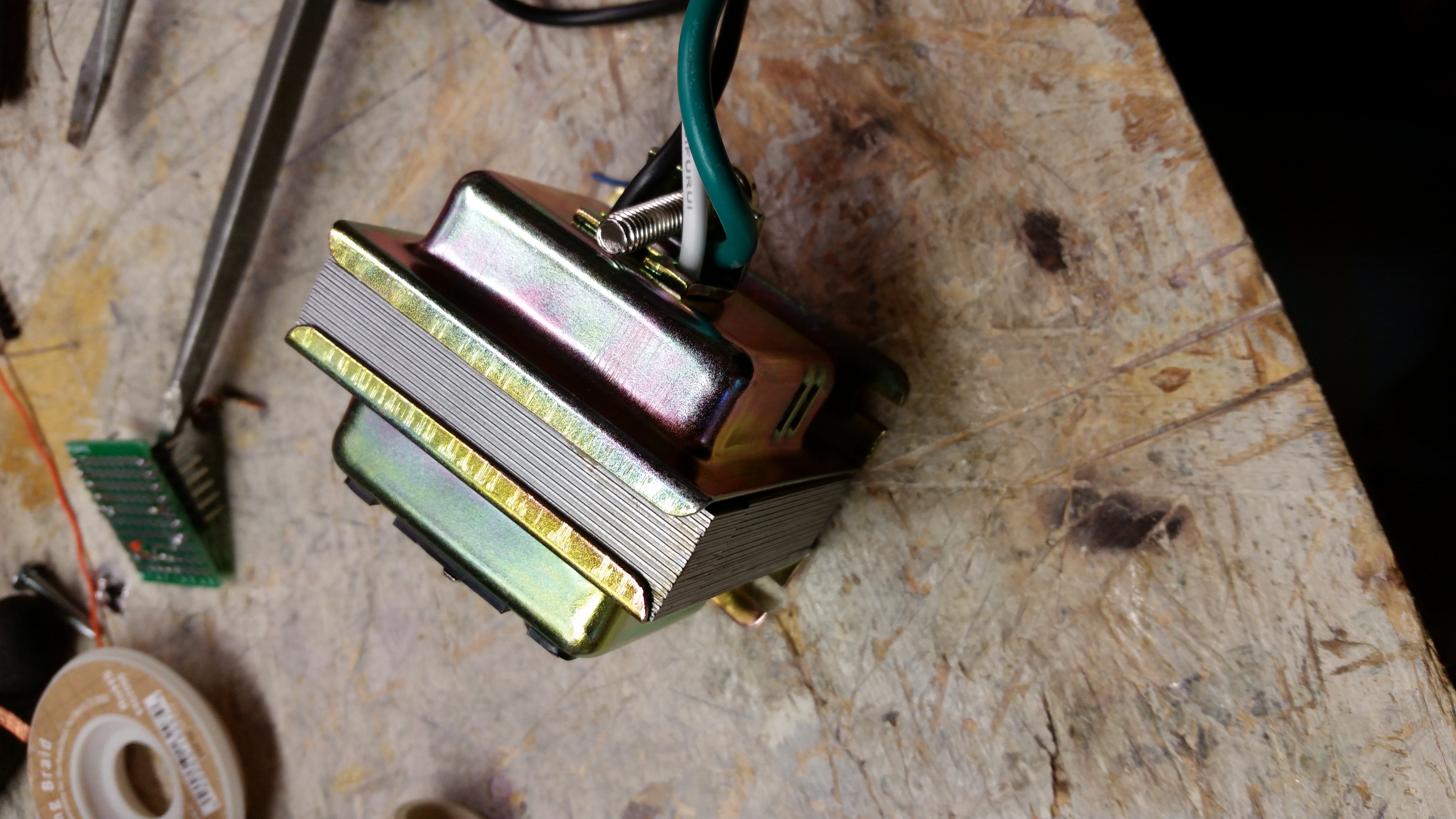
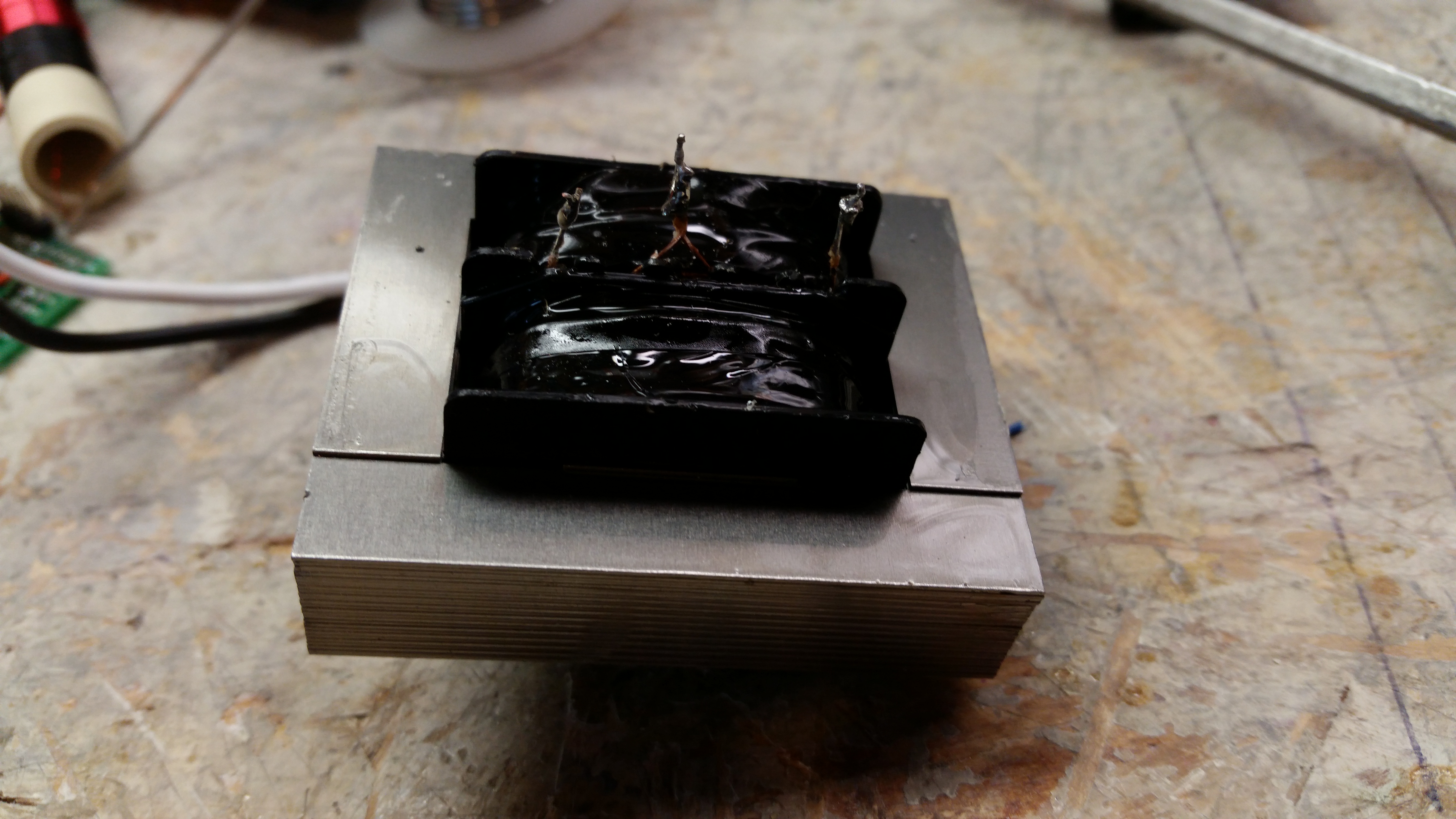
Backstory: I purchased some 24v pumps that I use in homebrewing beer. Lacking any good option for a 24v DC output, I grabbed a doorbell thermometer at the hardware store and rigged it up in a single-gang box (don’t try this at home, kids!).
For reasons likely involving moving boiling wort through one of these for 15 minutes before shutting off the heat (boiling wort is an effective sanitizer), I blew two transformers before looking into things.
-
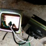
- Outside
-
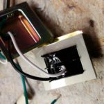
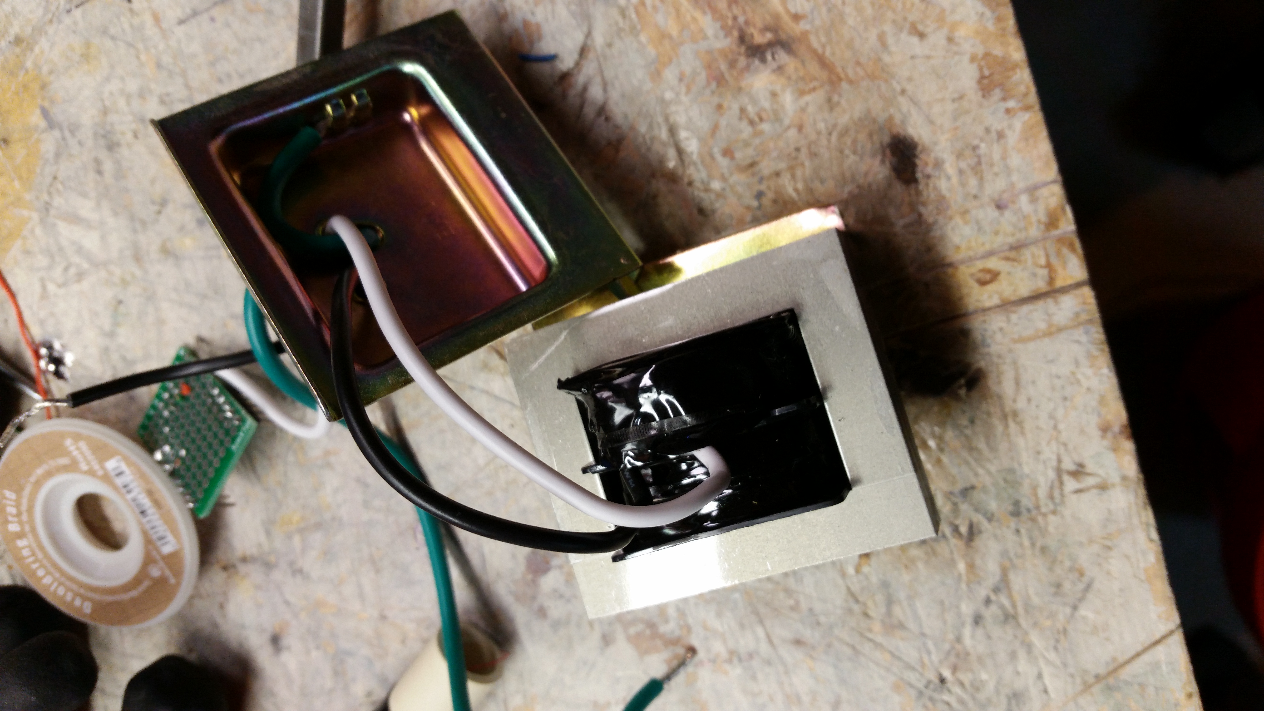
- Cover removed
-
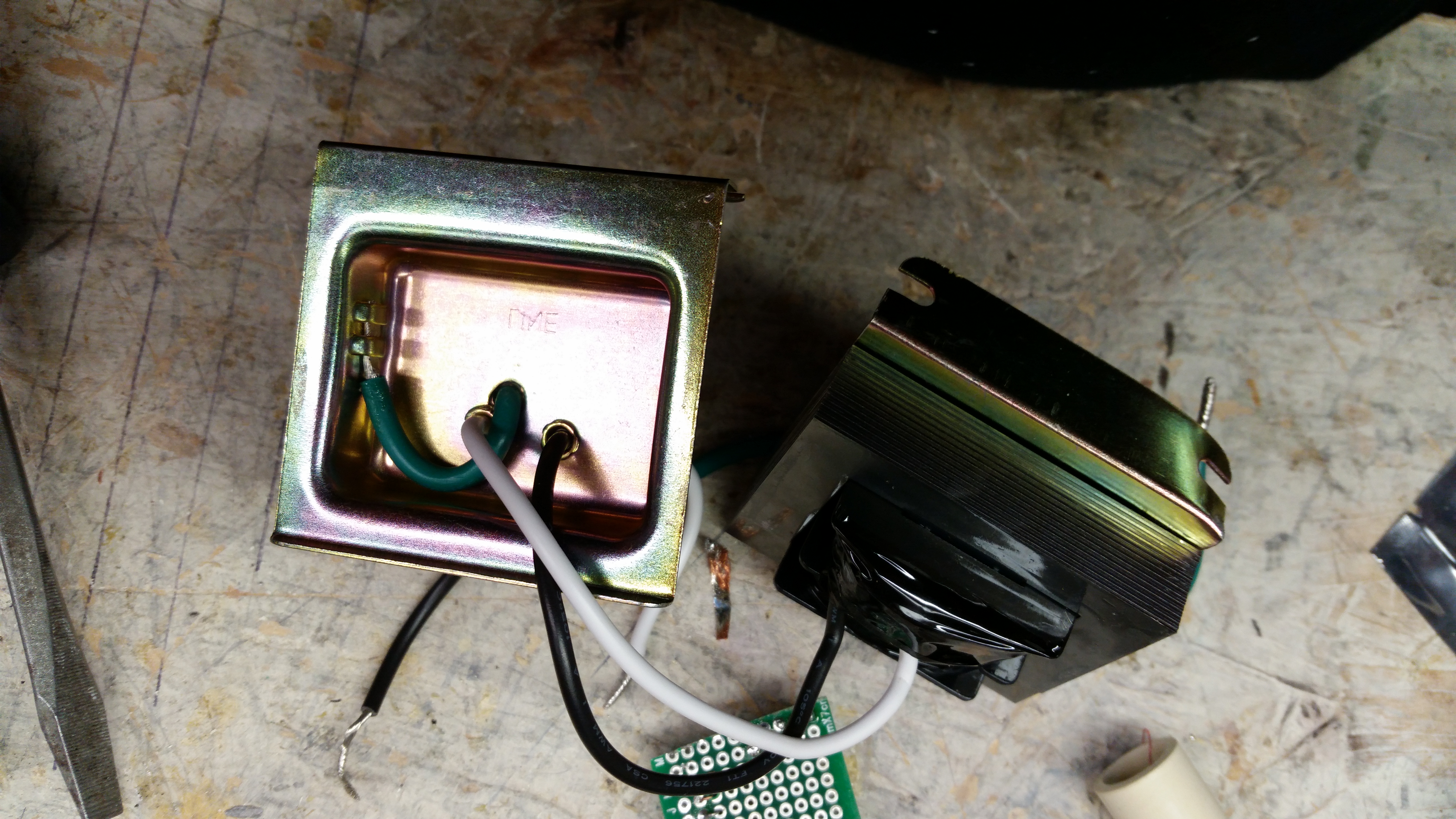
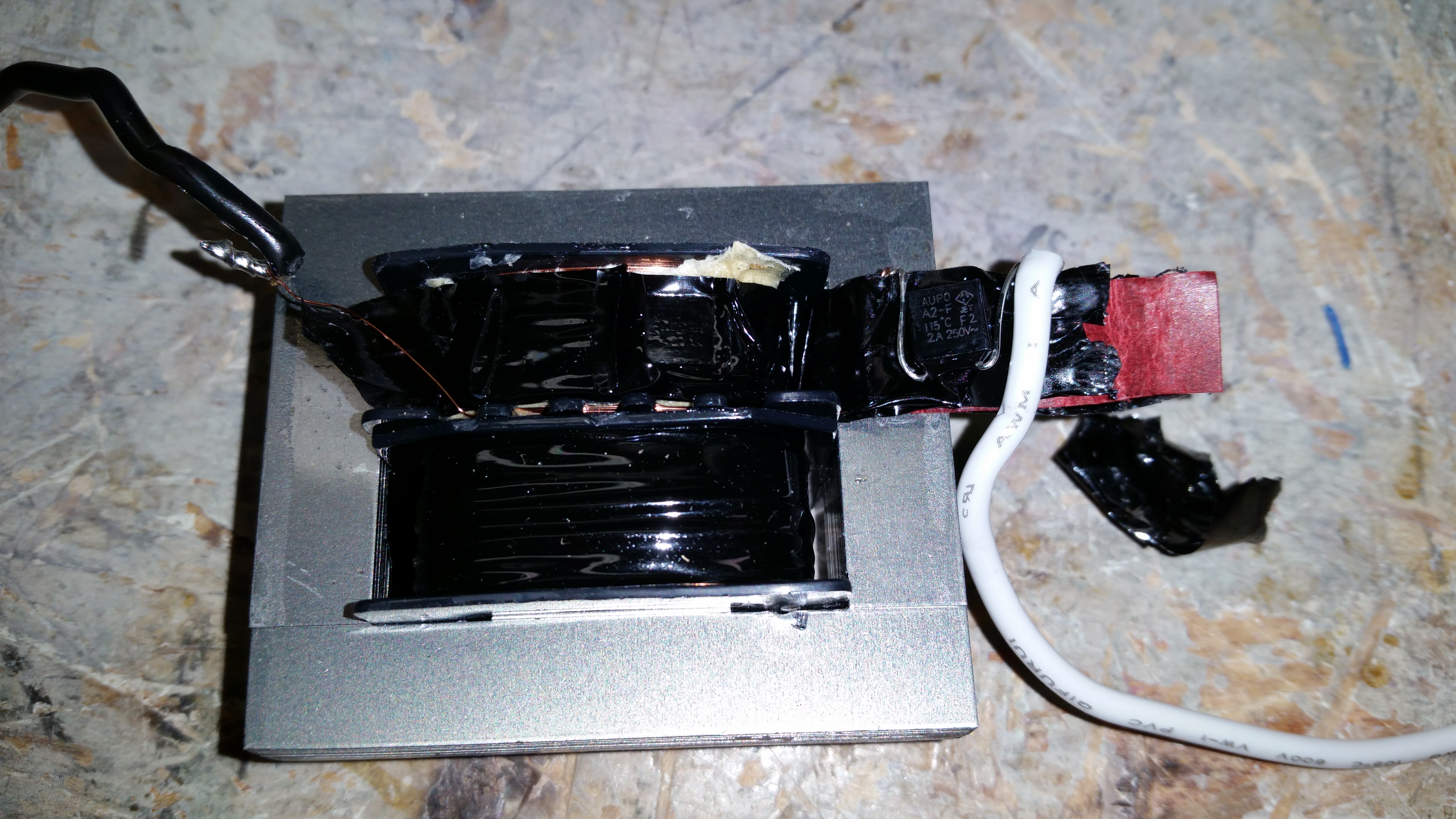
- Yup, it’s grounded.
-
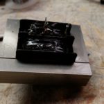
- Multiple taps – 8, 16, and 24V.
-
- The black part must be some sort of fuse, and that’s what failed. It says 2A on it, so apparently I had a pump pulling > 2 amps on the 120V side.
The ultimate end of this is that I’ve decided to stop using the cheap pumps and am going to purchase a decent pump.
-73-
Many years ago, I purchased a wine cooler on clearance at the local grocery store. I soon found why it was on clearance: it’s default set temperature was in the 30s (Fahrenheit) and it didn’t remember the set temperature after a power loss.
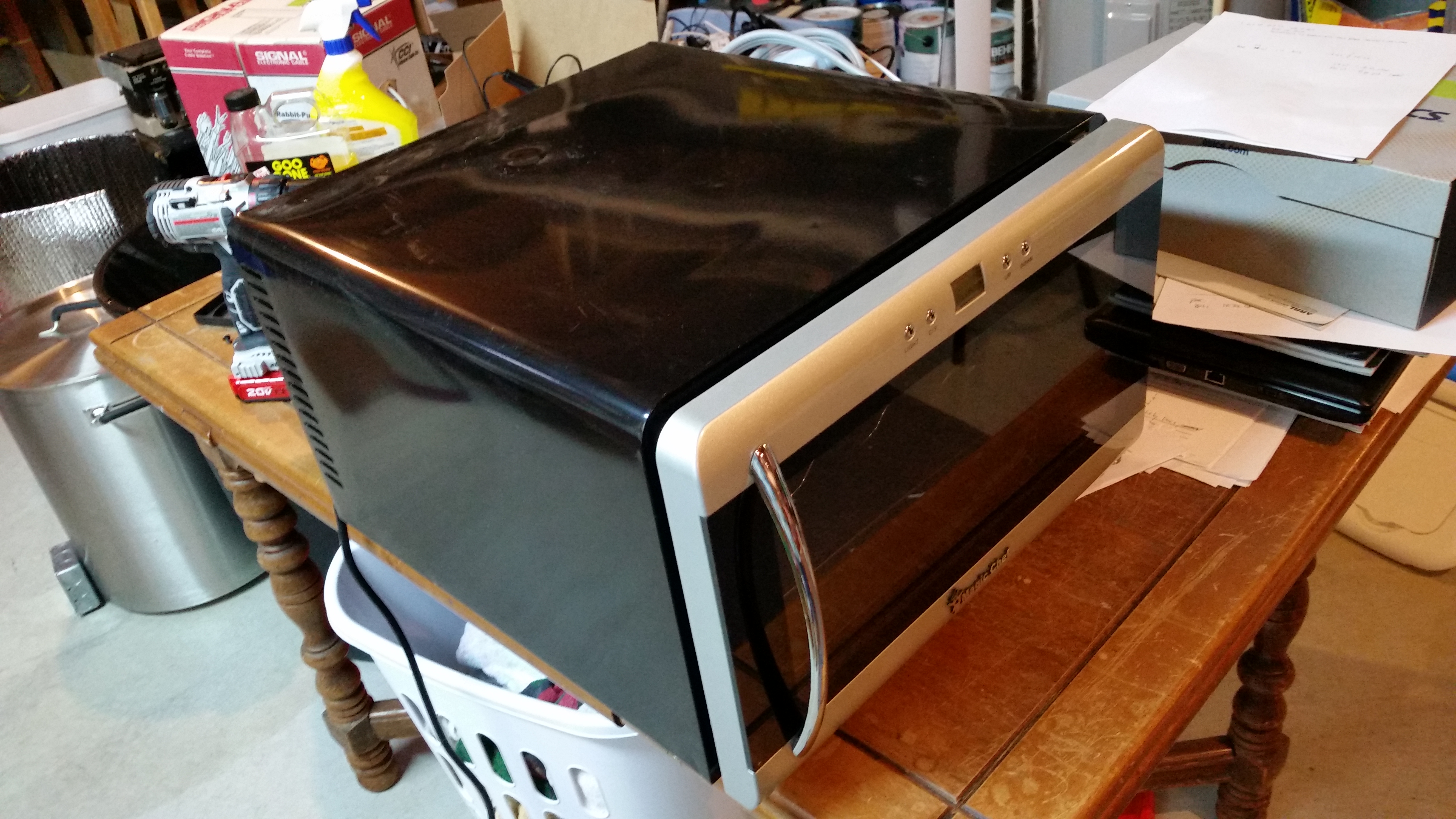
Wine cooler
So the wine cooler sat for many years, unused. Until now.
I don’t drink wine, but I brew beer. In brewing, yeast like certain temperatures – mid-60s to low 70s for ales, and mid-50s for lagers. While I normally brew ales, every so often I like a nice lager (few things beat a nice Marzen in the fall, or a nice Bock in the spring).
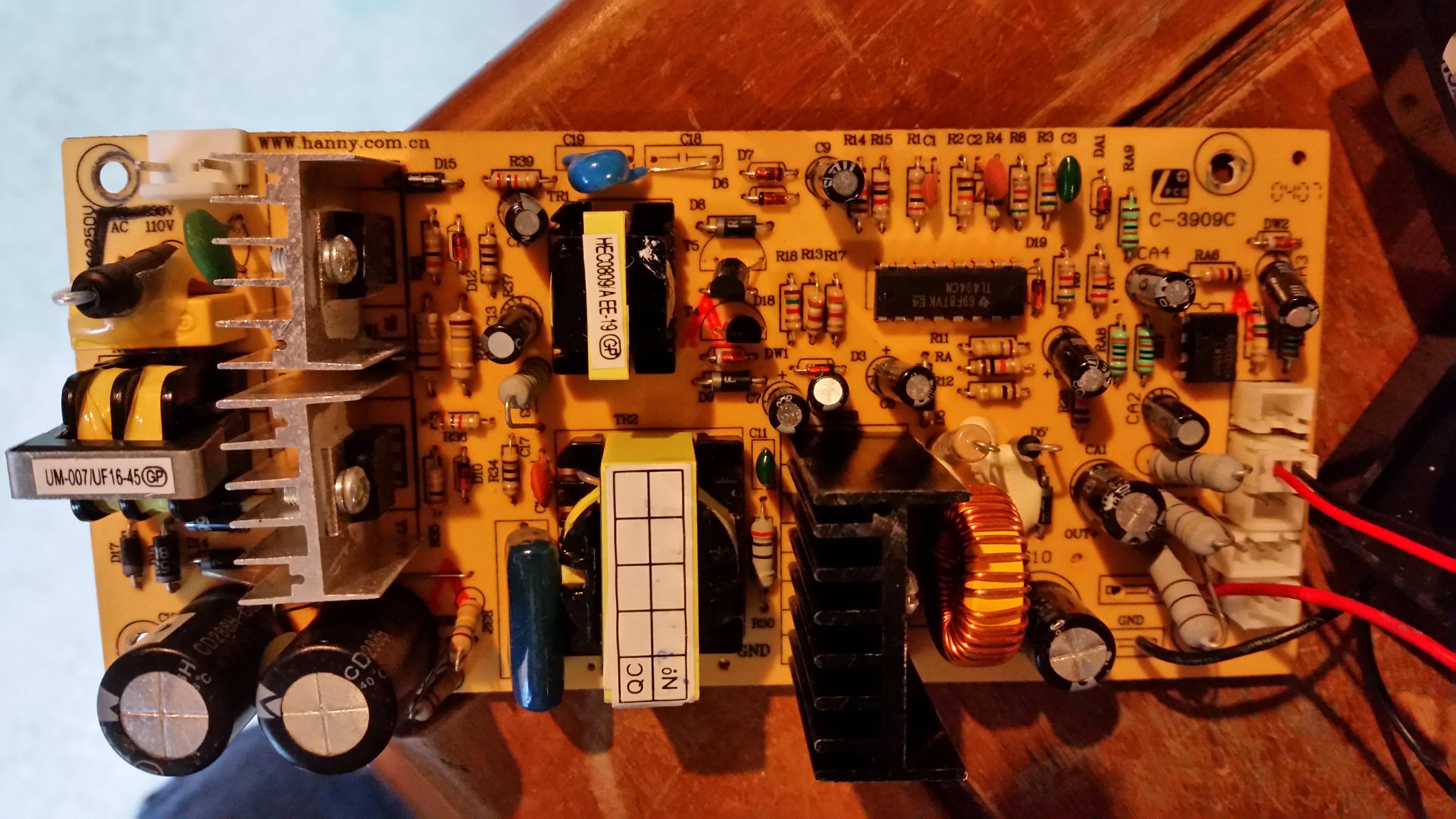
Top side of controller board
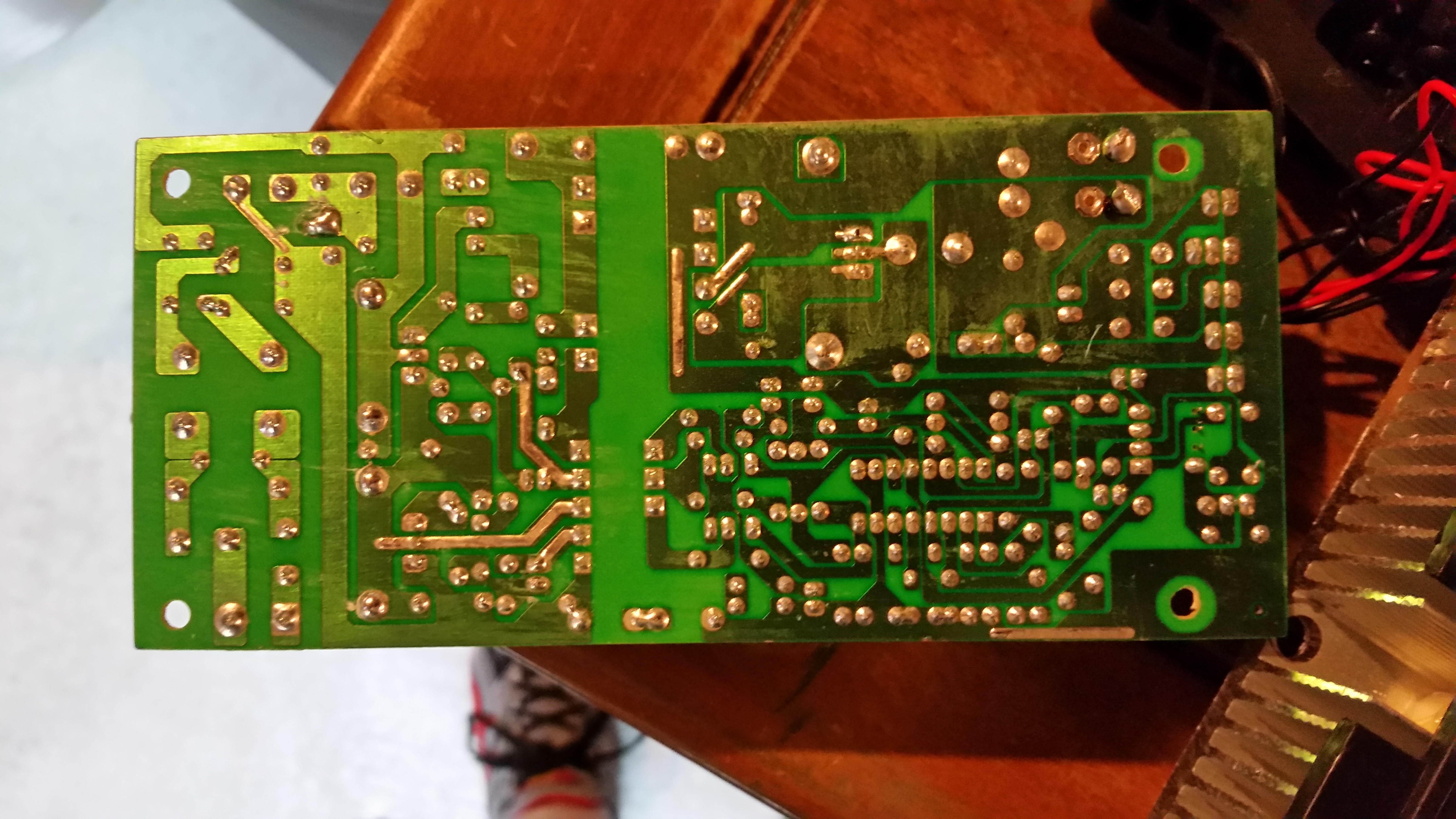
Bottom of controller board. Note the blank line between the high and low voltage sides of the the supply.
After taking apart the cooler, I realized it’s basically a switching 120V – 12V power supply with a controller for a negative temperature coefficient temperature sensor. Without anything connected to the NTC pin, nothing happens. However, if I short the NTC pin to ground, it turns on the chiller. As seen below in the headache-inducing video, the device works.
This is the first part – the second part will be a controller. And at some point, I’ll have to figure out if I can actually use this to keep 5 gallons of beer cold.
73
Update: removed the smaller (cold side) heat sink to get the part number. It is a TEC1-12706.
At a hot side temperature of 25ºC:
Qmax (Watts) 50
Delta Tmax (ºC) 66
Imax (Amps) 6.4
Vmax (Volts) 14.4
Module Resistance (Ohms) 1.98
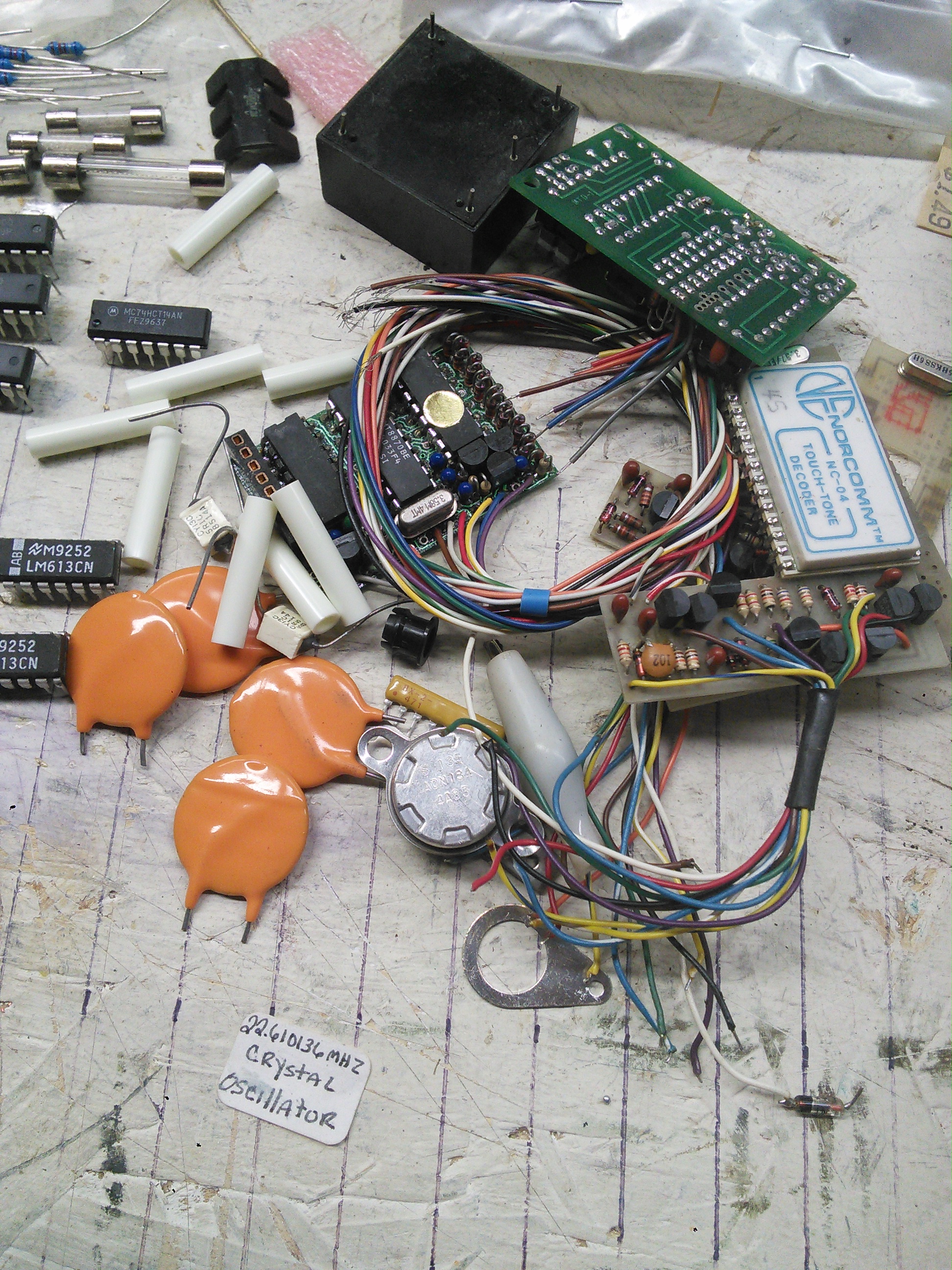
At the Milford Hamfest, Debco Electronics was selling off grab bags. I bought two (and I’m calling them Junk Box Fillers)… of note:
- 74155 ICs – 2 line to 4 line decoder/demultiplexers
- LM613 Dual Op-Amp and Dual Comparator and Adjustable Voltage Reference
- M5229P Seven Element Graphic EQs
- 15 trimmer resistors
- 9 variable resistors (8 appear to be the same)
- Some 2N4861 JFETs
- Some IRL530 MOSFFETs
- Some other bipolar transistors
- Some touch tone decoders (one not on a circuit board, at least one on a circuit board)
- Some display boards
Pictures:
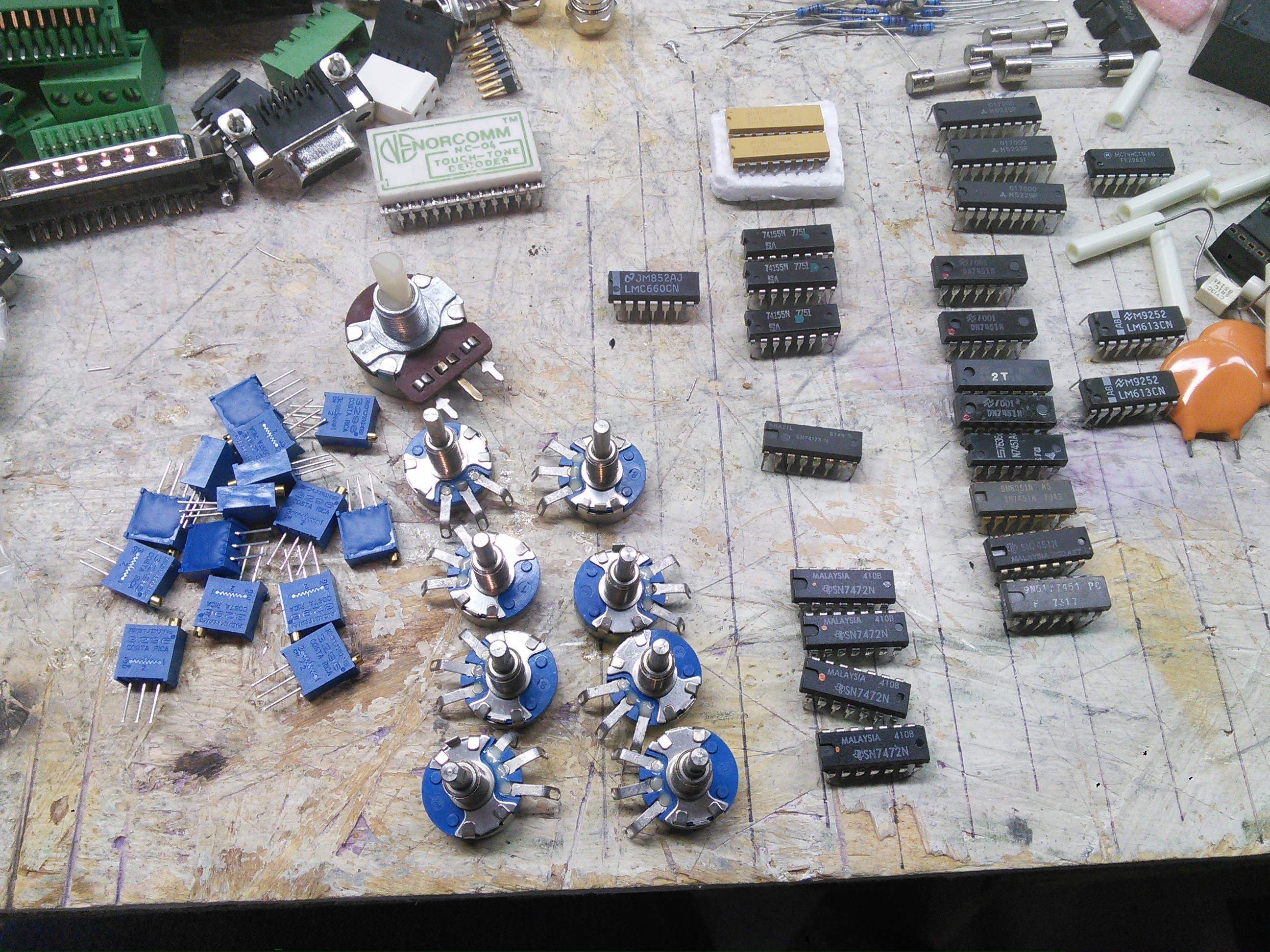
ICs, trimmers, variable resistors
Stuff that I don’t know what it is
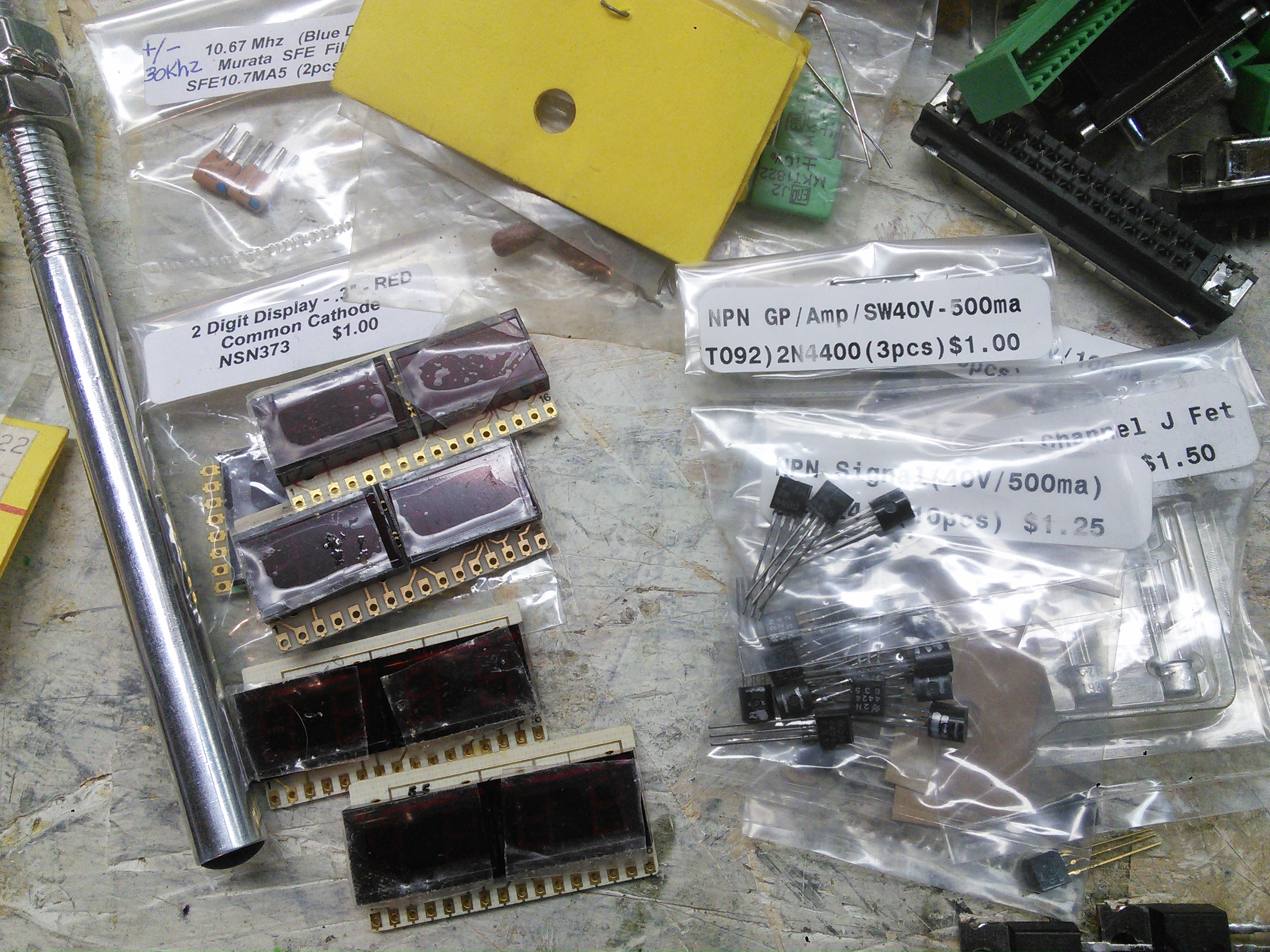
Displays!
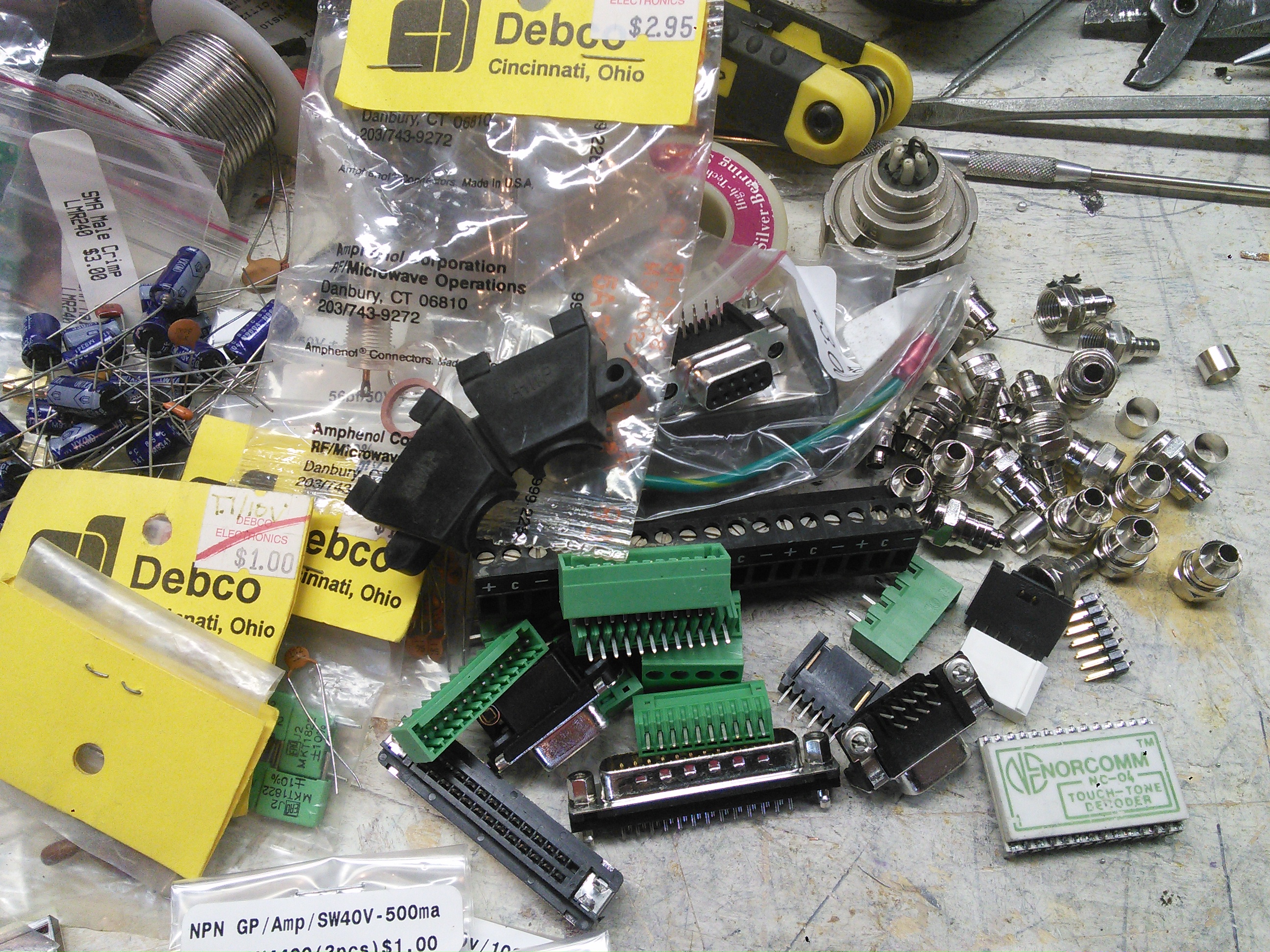
Jacks, connectors
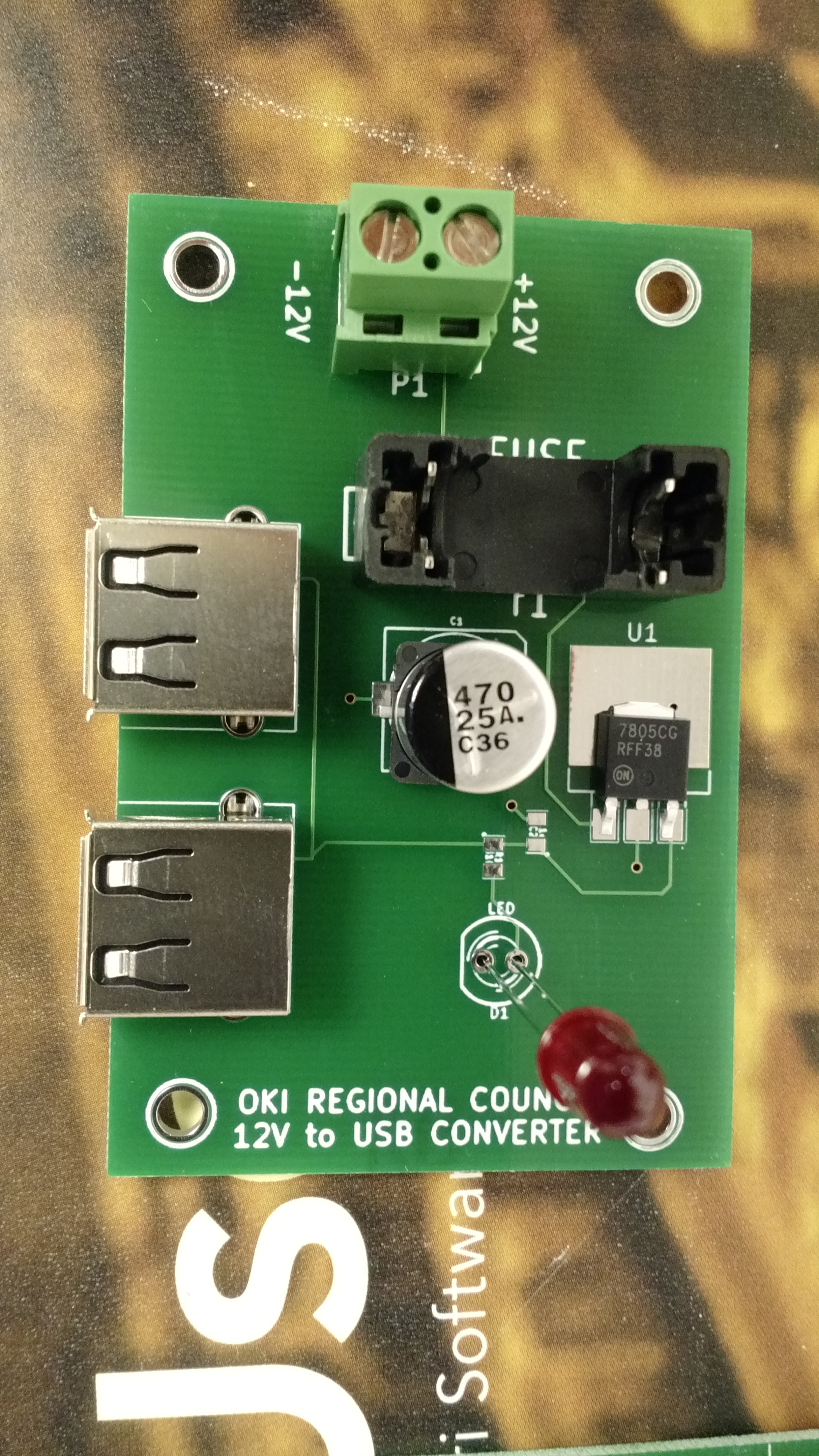
My work has taken me down the road of using Raspberry Pis as data collection devices. This means I need to power a Raspberry Pi in the field. I’ve had trouble finding a reasonably-priced 12V to 5V USB adapter that I could easily and safely fit into a box with a RPi. So I designed one in KiCAD and built it. The design is on my work github account.
I’m ultimately designing something that will connect to a battery, and batteries can explode if mistreated. Testing is critical, as is circuit protection (the fuse). I’m envisioning this to be in a box on the top of a pole with a camera, so the lead going from the battery (which will likely be on the ground) will be fused in case the wire gets cut. This is critical for the same reason it is necessary in a car – to protect the battery from short circuiting should something happen.
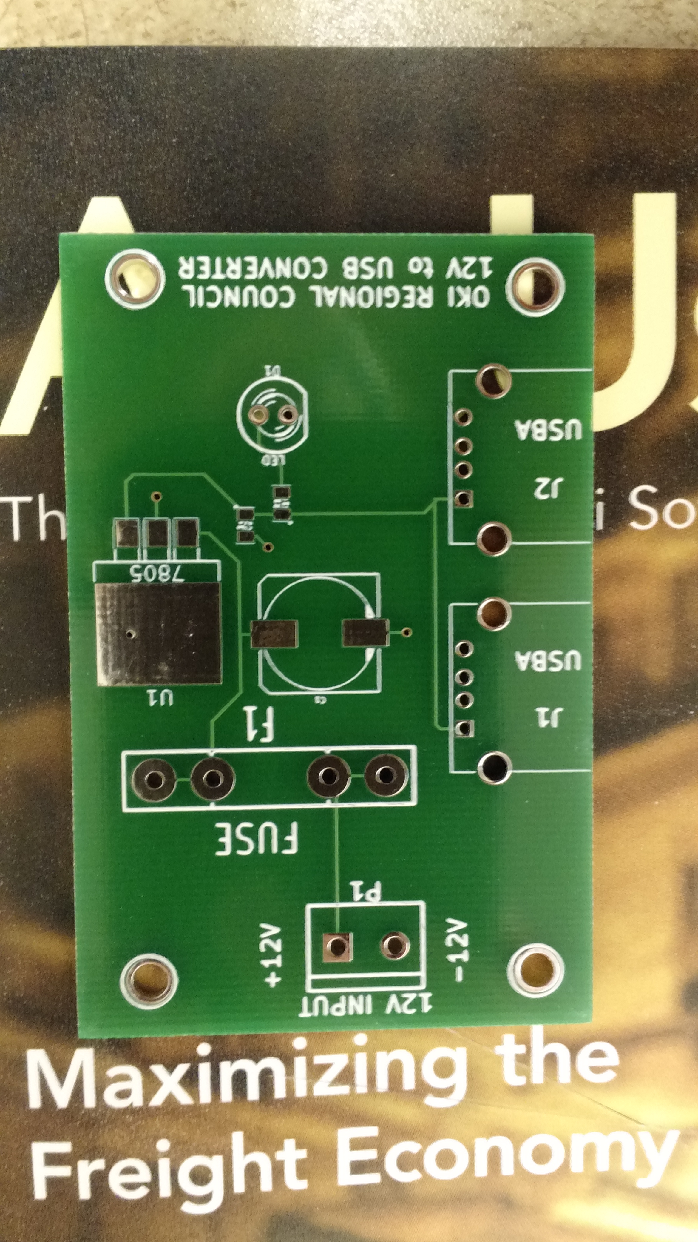
Empty PCB
Test fit components at the office.
In putting these together at home, I tested these in every way I could think of, and assembly and testing went something like this:
- Solder SMD C2 and R1
- Test resistance from 7805 output to LED positive solder hole, should be 330 ohm (I used 330 ohm resistors instead of 310, since I don’t happen to have any 310 ohm).
- Test continuity from 7805 output to ground via connected to C2. Should show no continuity.
- Solder USB connectors and C1
- Test capacitance from 7805 input to to ground via near C1. Should show a reading (mine all showed around 1000 uF, which is high, but my understanding is that multimeters are notoriously bad at capacitance)
- Add input headers, fuse holder, and LED
- Test continuity between inputs – should immediately beep, and then drop to no continuity after capacitors charge
- Apply voltage, LED should light, all magic smoke should remain contained in devices
- Test voltage from 12V- to 7805 output – should be 5.0v (mine showed something like 5.007v)
The one thing I was unable to test was the actual USB output voltages, but it seems to me that they should be okay.
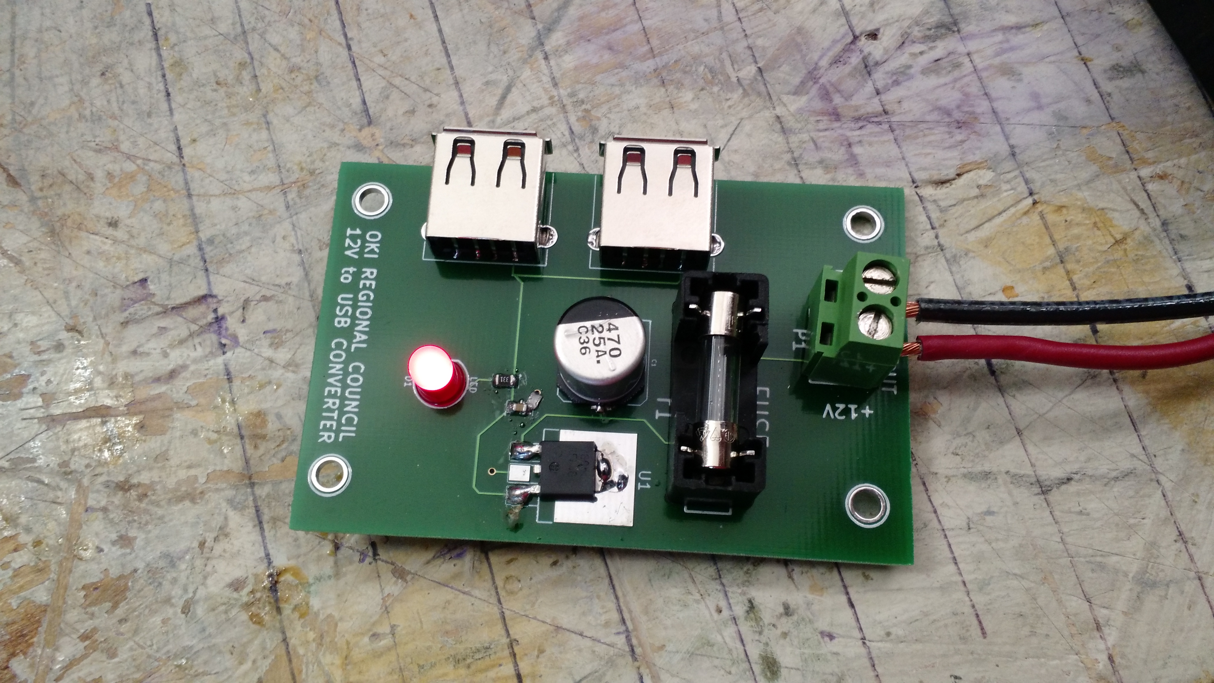
IT LIVES!!! This is one of 5 I built.
I have five blank PCBs left for additional builds should I need it, although I’d have to have work buy more components. Maybe I could get some larger 7805s that would fit the ground pad…
-73-
I decided to build a Colpitts oscillator after watching one of W2AEW’s videos.
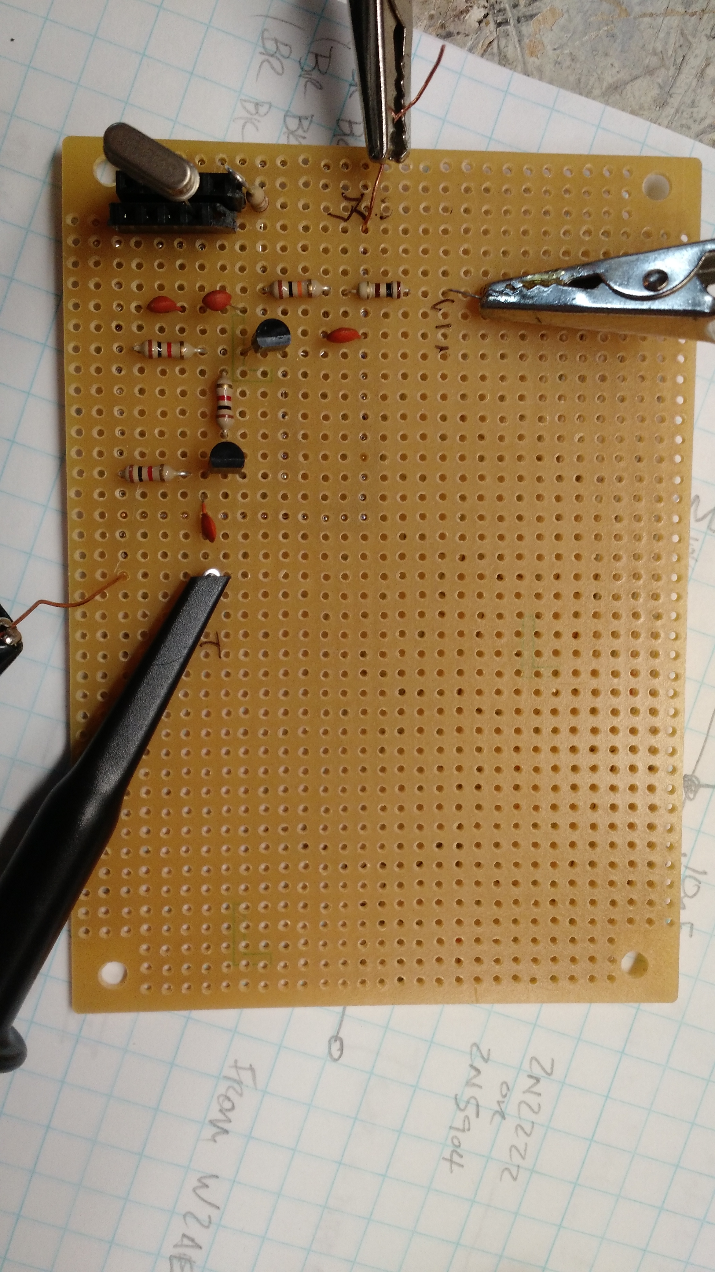
Circuit Board
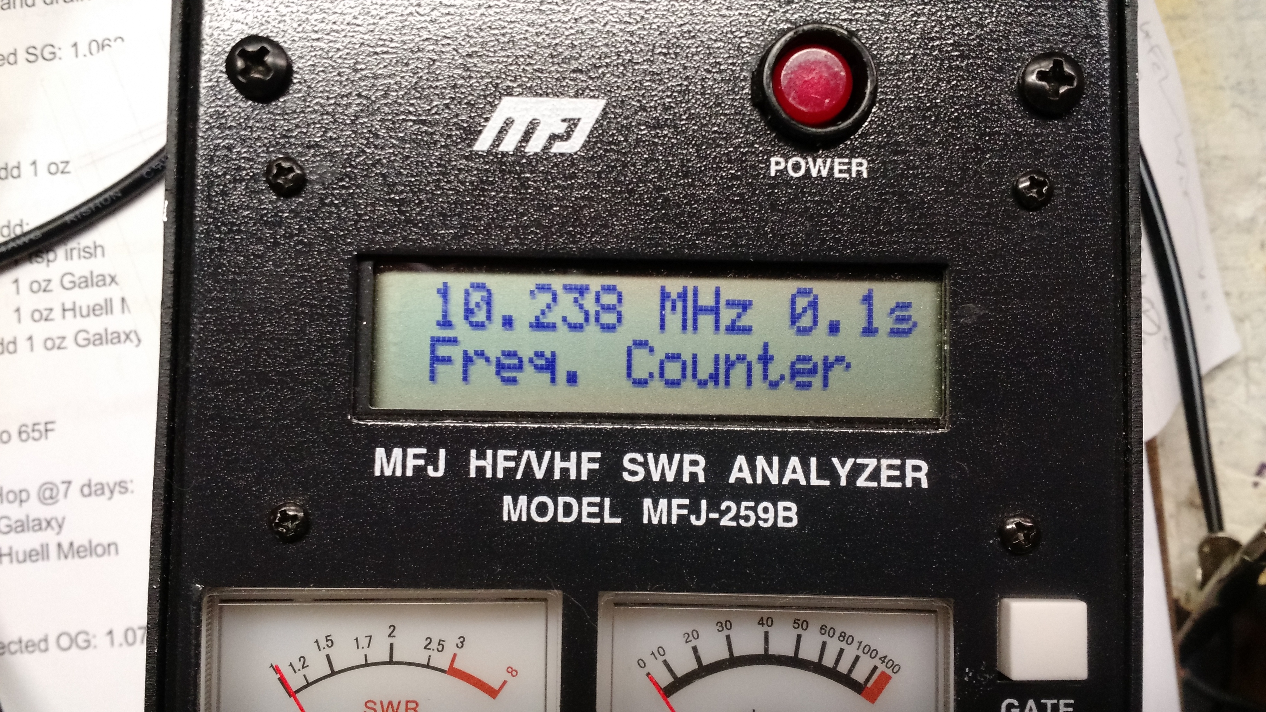
Frequency Counter
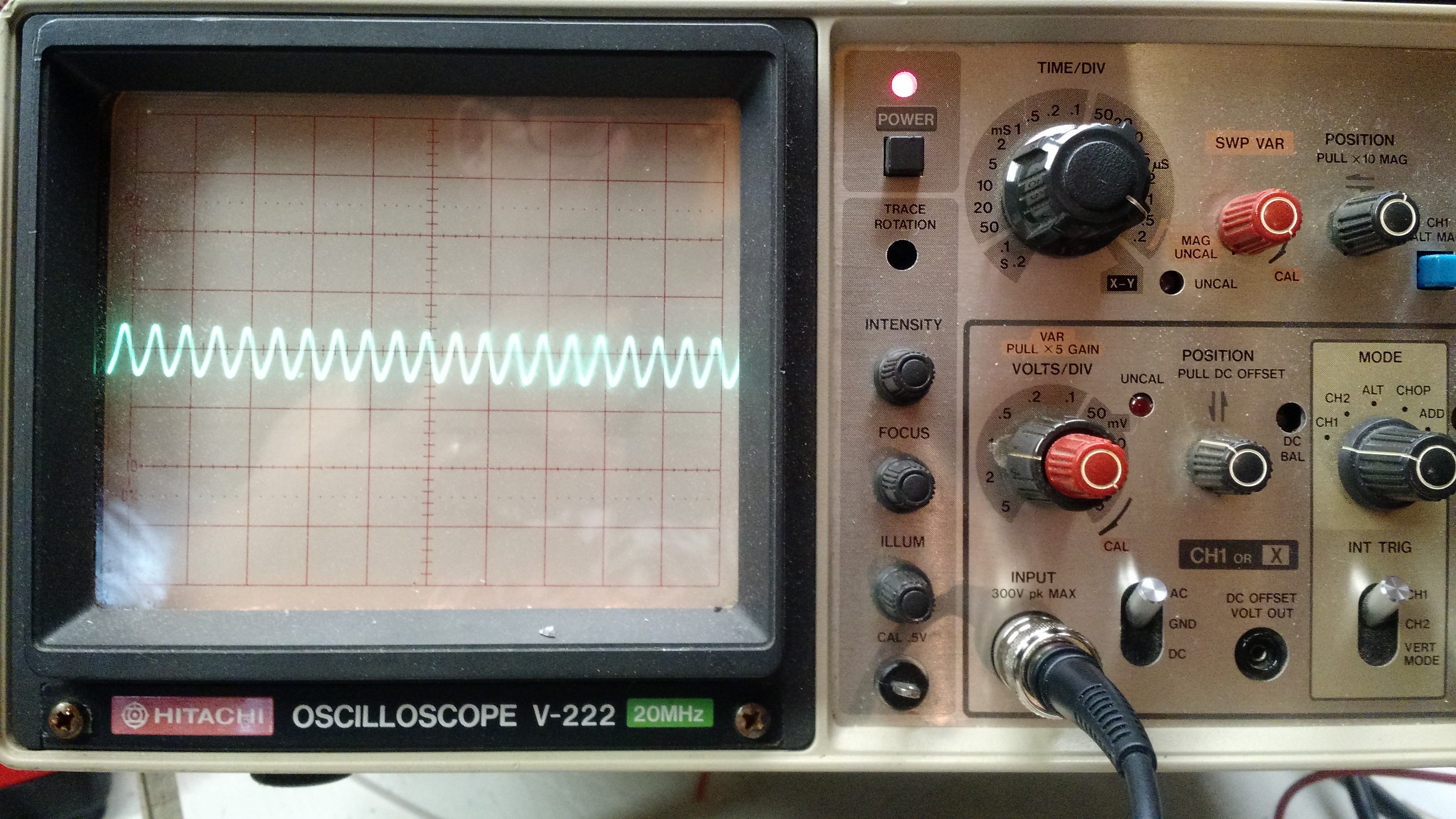
Waveform on the scope
The only issue I ran into was that I had the power supply hooked up backwards, so when I initially connected it to the scope, the +12V shorted to ground (and it burned a small hookup wire in the process). I should have paid more attention to the testing that W2AEW describes in his video – on a second try, I was seeing -7V where I should have been seeing +5V. And I shouldn’t have trusted the two hookup wires I was using to get from a computer power supply output to a circuit.
I also didn’t have 2N2222 or 2N5904 transistors, I used 2N3904s, which seem to work fine.
-73-
This is the second part of something that has been sitting on my workbench. Part I.
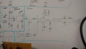
The schematic…
The video below shows the two traces of the input and the output of the second JFET.
The board is coming together as much as it could be for not being printed or having an enclosure.
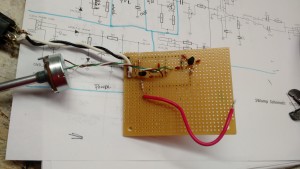
Through the tone control
The third part will be waiting for me to order a few pots, which I forgot to put on my last parts order.
-73-
With all the issues surrounding FTDI chips and drivers, I decided I’d look at a competing chip – the Microchip MCP2221. Unlike the “standard” FTDI FT232 (which is most similar to the MCP2200), the MCP2221 includes both a UART and an I2C interface.
Hookup and Configuration
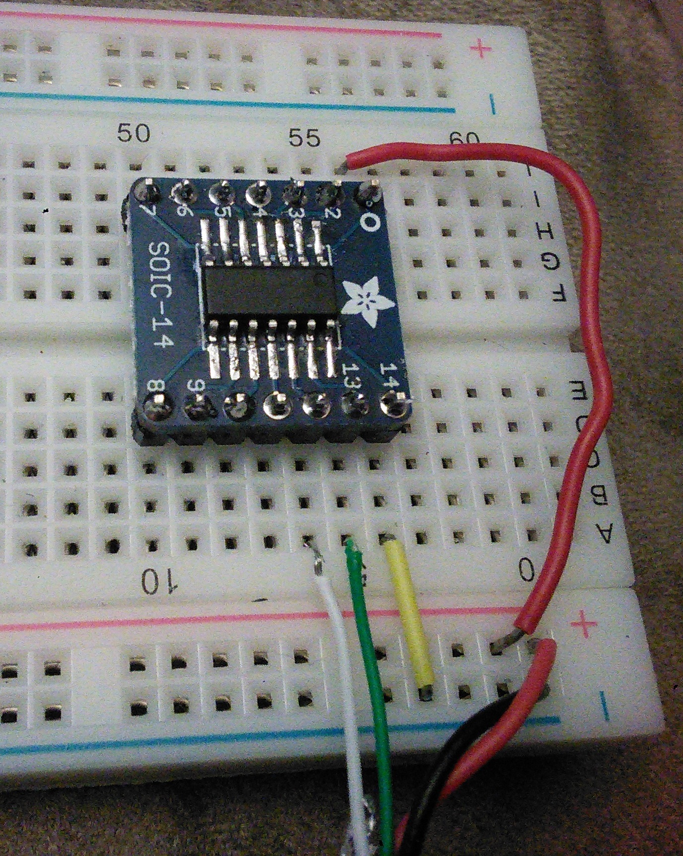
Hookup
Hooking up this is pretty easy. I sacrificed a USB cable and pulled the red to Vcc on pin 1, black to ground on pin 14, white to Data- on pin 12, and green to Data+ on pin 13.
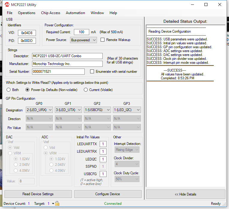
After that, I checked things using the Microchip MCP2221 Utility from Microchip. One of the more interesting things in the utility was being able to configure four pins:
GP0 (pin 2), default is UART RX LED, but can also be SSPND (suspend?) or GPIO
GP1 (pin 3), default is UART TX LED, but can also be CLK_OUT (clock out?), ADC1, IOC, or GPIO
GP2 (pin7), default is USBCFG, but can also be ADC2, DAC1, or GPIO
GP3 (pin 8), default is I2C LED, but can also be ADC3, DAC2, or GPIO
I2C Connection
The real reason I got this was to be able to interface to both I2C devices and UART (serial) devices, so I hooked a TC74 temperature sensor to it.
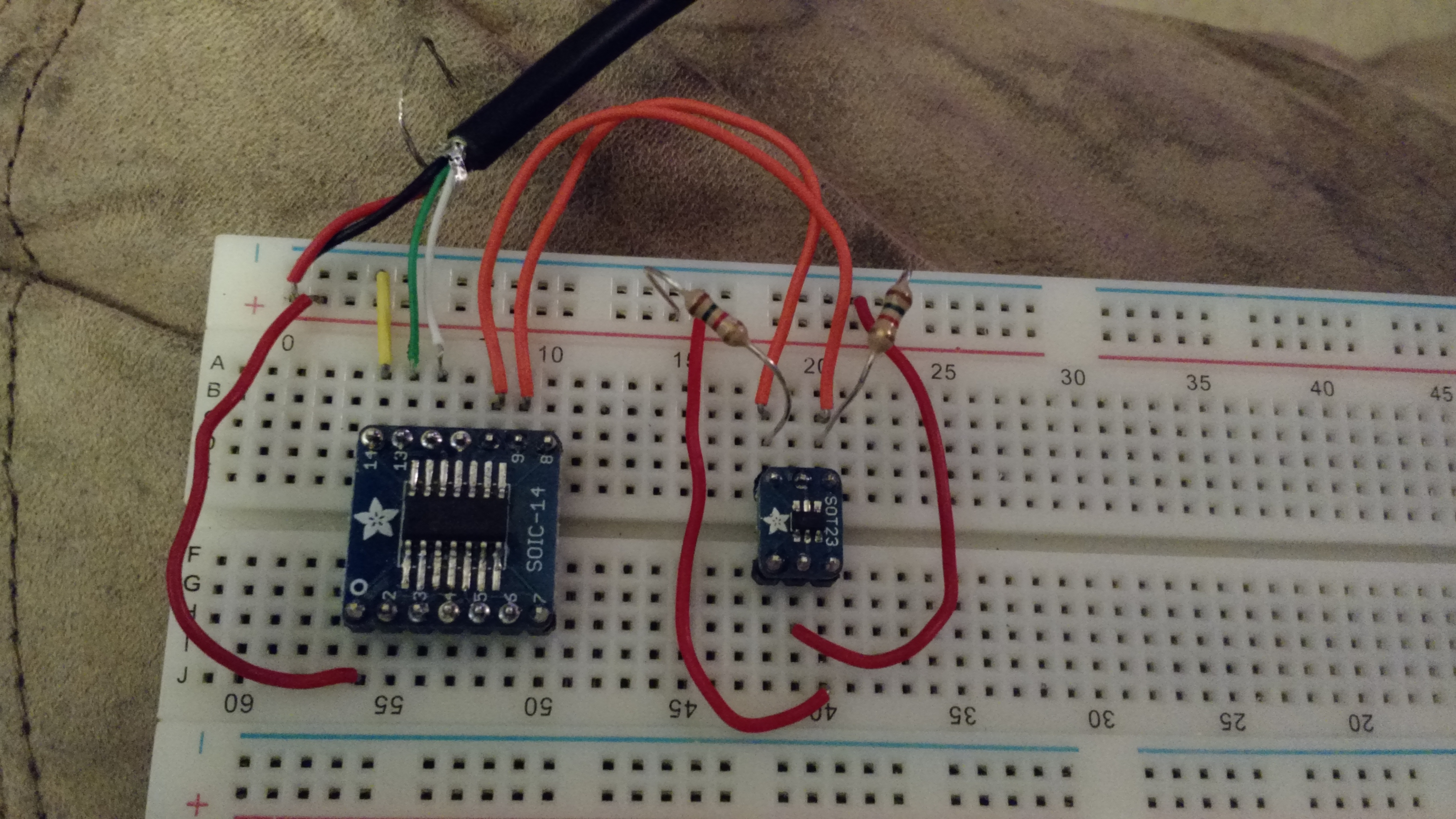
TC74 hooked up to the MCP2221
The hookup is straightforward, the TC74 uses four of it’s five pins, Vcc, ground, SCL, and SDA. Vcc and ground are pretty self explanatory, SCL and SDA go to pins 10 and 9 on the MCP2221 (respectively). The SCL and SDA lines need pull-ups, I used 1.5k resistors.
To check things, Microchip provides an I2C/SMBus Terminal program.
Under “Advanced settings” you can scan the bus by giving it a range to scan…
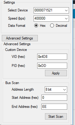
Scan the entire bus
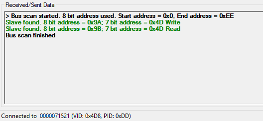
Scan results. Found the TC74 right where I expected it.
Once I verified that the sensor was where I thought it was, I used the terminal tool to read it…
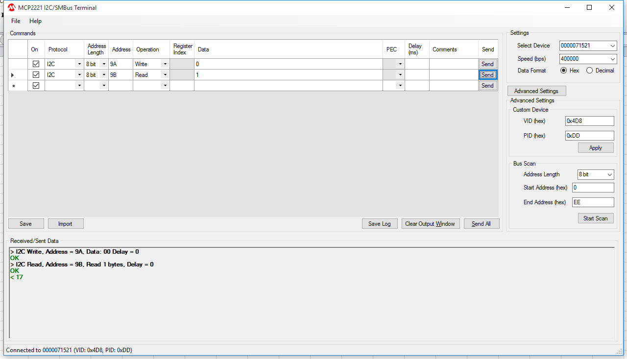
0x17… 23C… 74F…
So the next steps are to figure out what I want to do with all this… I’m partly thinking a multi-function breakout board – UART, ADC and DAC
-73-
Backstory
Many months ago, my brother-in-law brought over a guitar with the thought of “you fix it, I’ll cover the costs, and we’ll split the profits”. It wasn’t a bad deal, so I started fixing it. A month later, after I preceded to remove a large part of the partially-damaged finish, he called and told me that he got another guitar and he was no longer interested in pursuing it.
So it sat for many weeks.
And it sat for a few more weeks.
Finally, the same brother-in-law brought over a Marshall head that blew a fuse and a few diodes to repair. I needed a guitar to test it with, so I finished stripping it and ended up with something that looked decent and actually played (which I ultimately used to test the amp).
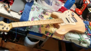
Guitar
Around the same time, Hack-A-Day posted about the 1Wamp, a small, battery powered amp. The schematic looked like an easy build, and I was fairly certain I had all the parts lying around.
Amp Build Part 1: The Preamp
The preamp is very simple: 3 resistors and a JFET.
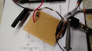
Yeah, pretty simple.
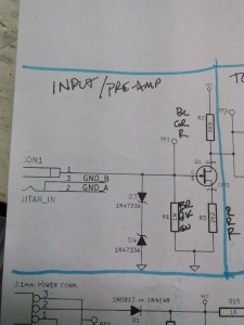
Simple Schematic (well, this part is, anyway)
I skipped the Zener diodes, which are there for static protection. I’ll probably add them in at some point in the near future.
It does work. I hooked it up to a 12V linear power supply and took a video of the input (from the guitar) trace and the output trace from the preamp.
The input is about 0.6 – 0.8 Vp-p. The output is about 1.6 – 2.0 Vp-p. That puts it somewhere in the range of 6-8 dBV. That’s a little over spec, but I’m also feeding it 13.8V instead of 9.0 – 9.5V.
Next up: the Tone Control. zOMG 6 components!
73!