
Category Archives: Equipment
I’ve had a mobile radio installed in my S-10 for years. However, for the longest time, it was only half right. I did the correct thing and not use my truck’s accessory outlet wiring. I haven’t figured out for the life of me how General Motors claims you can put 20A on a 20 gauge wire – 20A for any sustained period of time on such a small wire is a significant fire hazard.
This is the wrong way to do this.
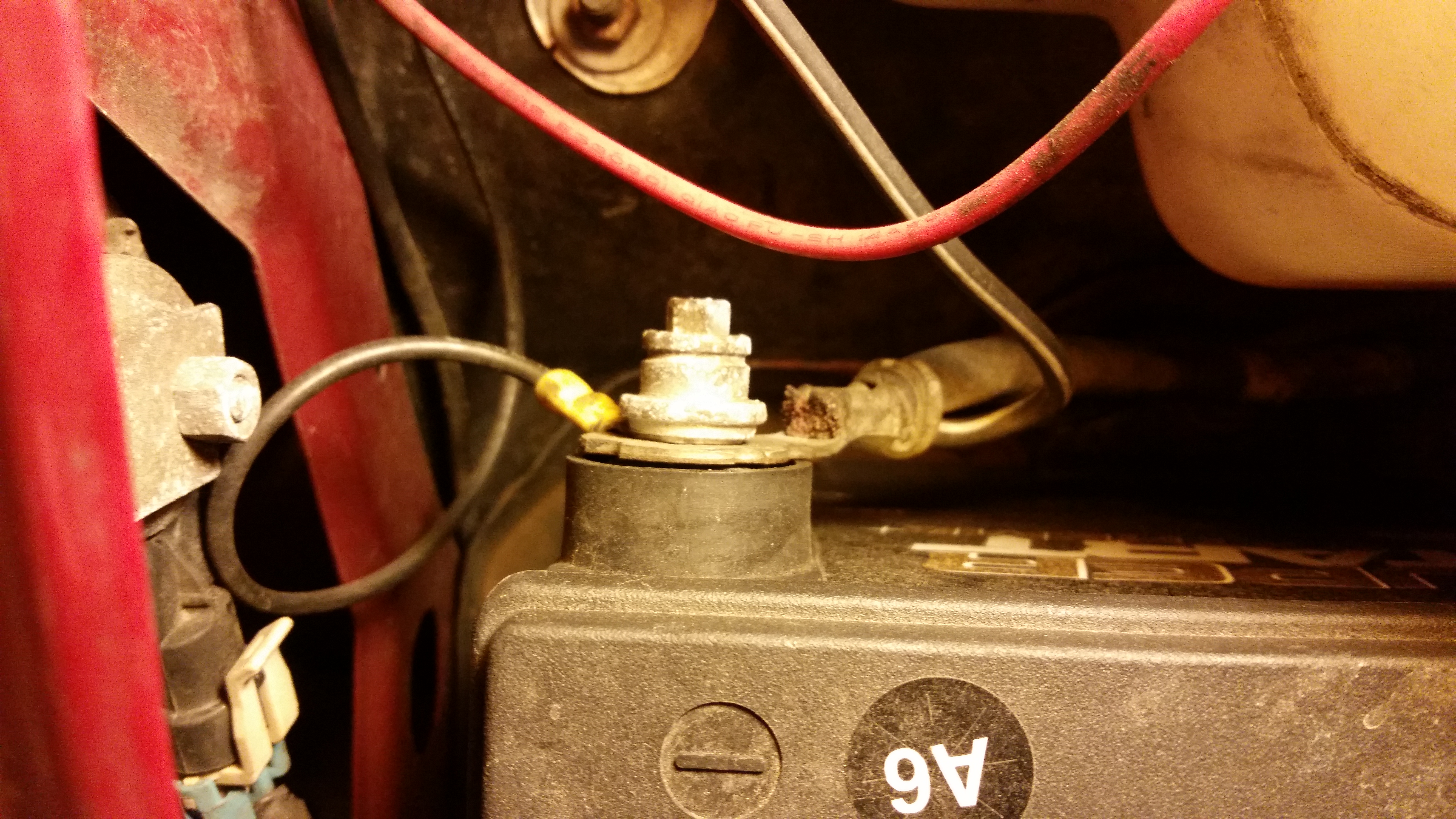
Initially, I took the quick, easy, and cheap way out by sandwiching the radio power lead in the battery post. However, I ran into a problem a few times in the mornings where my truck wouldn’t start. I found that the positive power lead was not staying tight. I eventually removed the power lead because I like to be able to drive my truck. And besides, no power was getting to the radio, either!
Enter the correct solution.
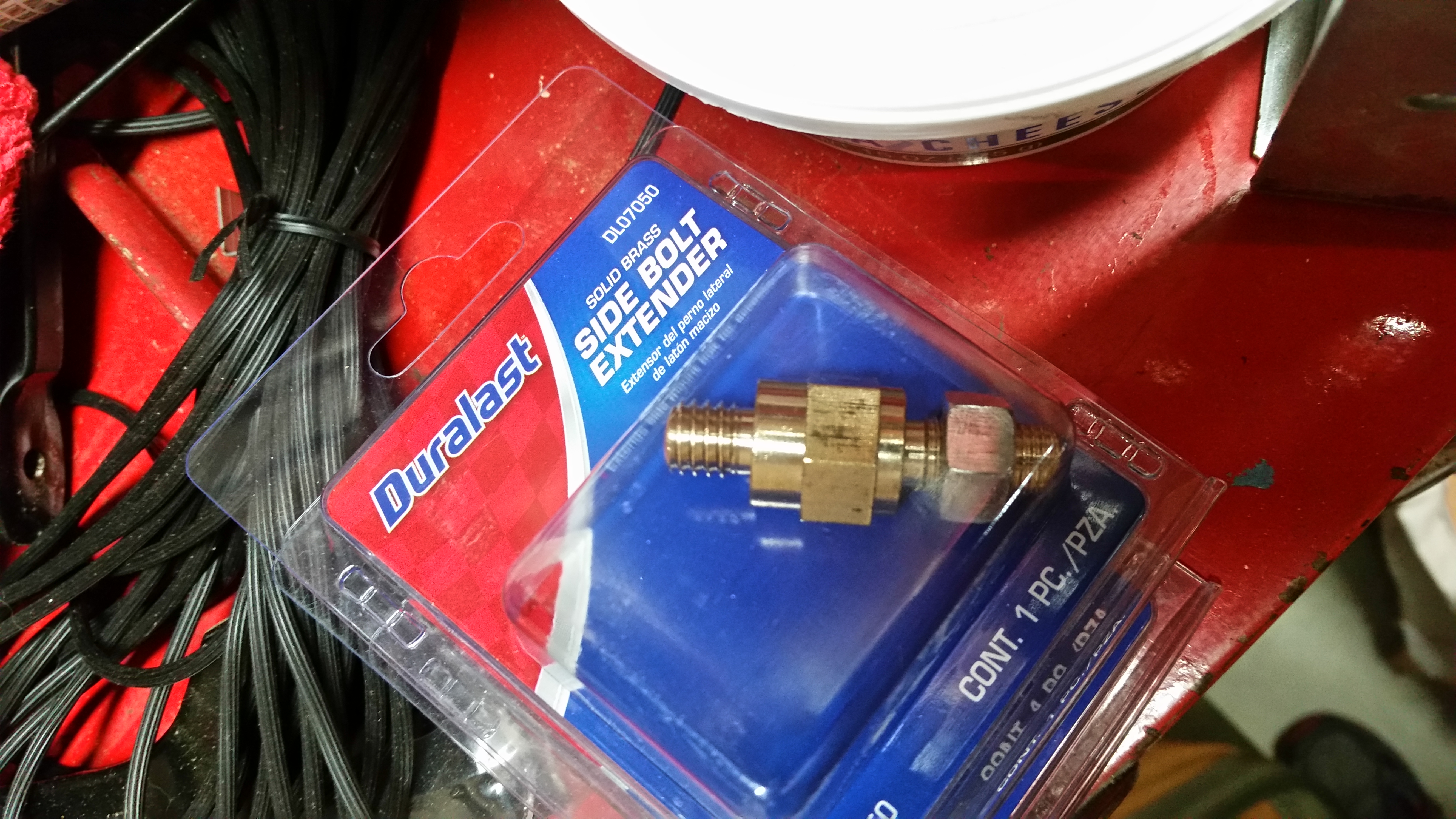
Better Battery Bolts
The correct solution is $5 each (and two are needed). Not really expensive.
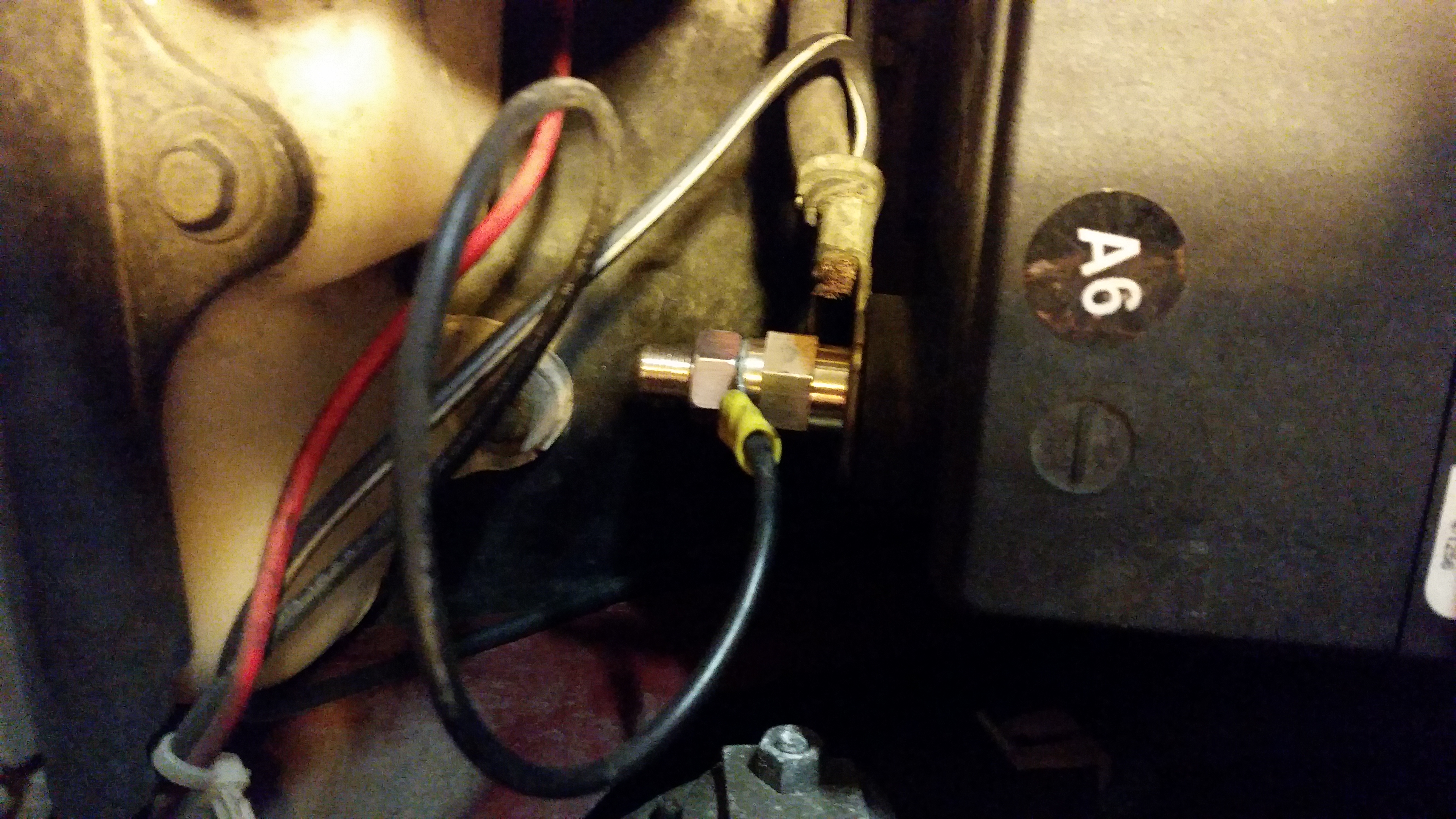
The correct solution
This works better for two ways – the first is that the new battery bolts are longer ensuring a more reliable connection between the battery and the cables. The second is that the wires are not between the battery and the main vehicle power. I might be over-stating that benefit, though, as I don’t think the power lead lugs were causing any significant power drop.
73 de KE8P
Some time ago I built an Internet gateway (iGate) for monitoring APRS packets and sending them to APRS-IS. It never made it to the blog partly because it was built out of Direwolf, so it was mostly software configuration.
Since then, I’ve had trouble keeping soundcards running in the same configuration and the iGate was offline for some time.
Last summer (or the one before it, I don’t remember), I bought the components to a packet station: an AEA PK-232 TNC, a Kenwood Mobile, and a broken power supply. The broken power supply is still broken, but the rest is up and running.
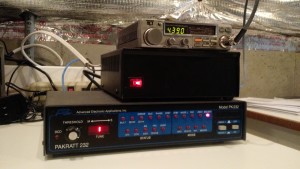
The APRS Receiver Setup
The setup for the PK-232 is courtesy of LA6YIA on Google Groups:
XFLOW OFF
AWLEN 8
PARITY 0
RESTART
CONMODE TRANS
TRACE OFF
HID OFF
BEACON EVERY 0
PACKET
RAWHDLC ON
HPOLL OFF
PPERSIST ON
KISS ON
HOST ON
The APRX setup is not groundbreaking, but it’s below, too, since it may help someone…
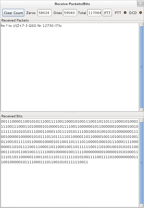
Then, since the ultimate test is to make it work, I wrote a simple Arduino Sketch using the Argent Data APRS Arduino shield and my trusty IC-T90A…
Obviously, this only transmits once, and it is using manually-entered location, but it does the job.
Look! It’s here!
And of course, I could find some repeats in the log:

I’m in the log!
So at this point there should be better coverage in the far east of Cincinnati.
73!
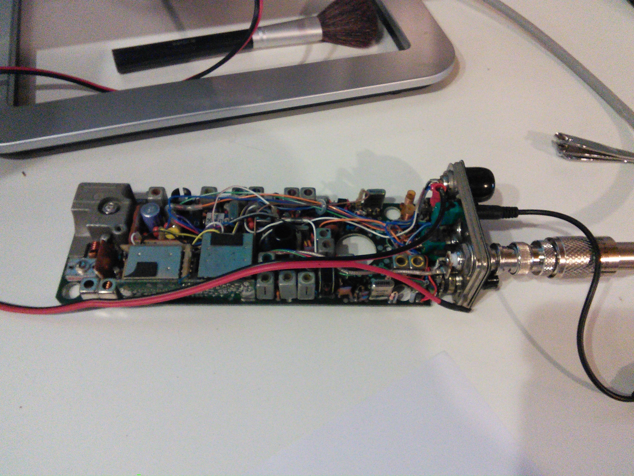
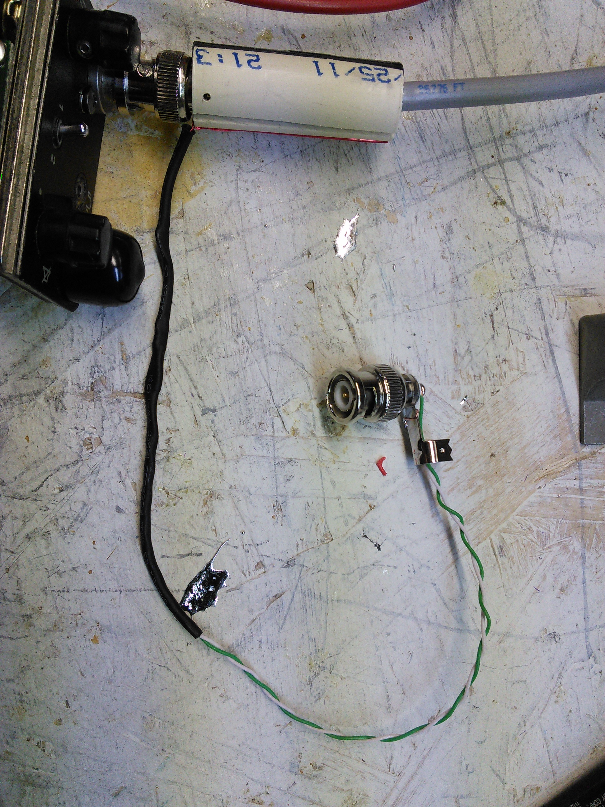
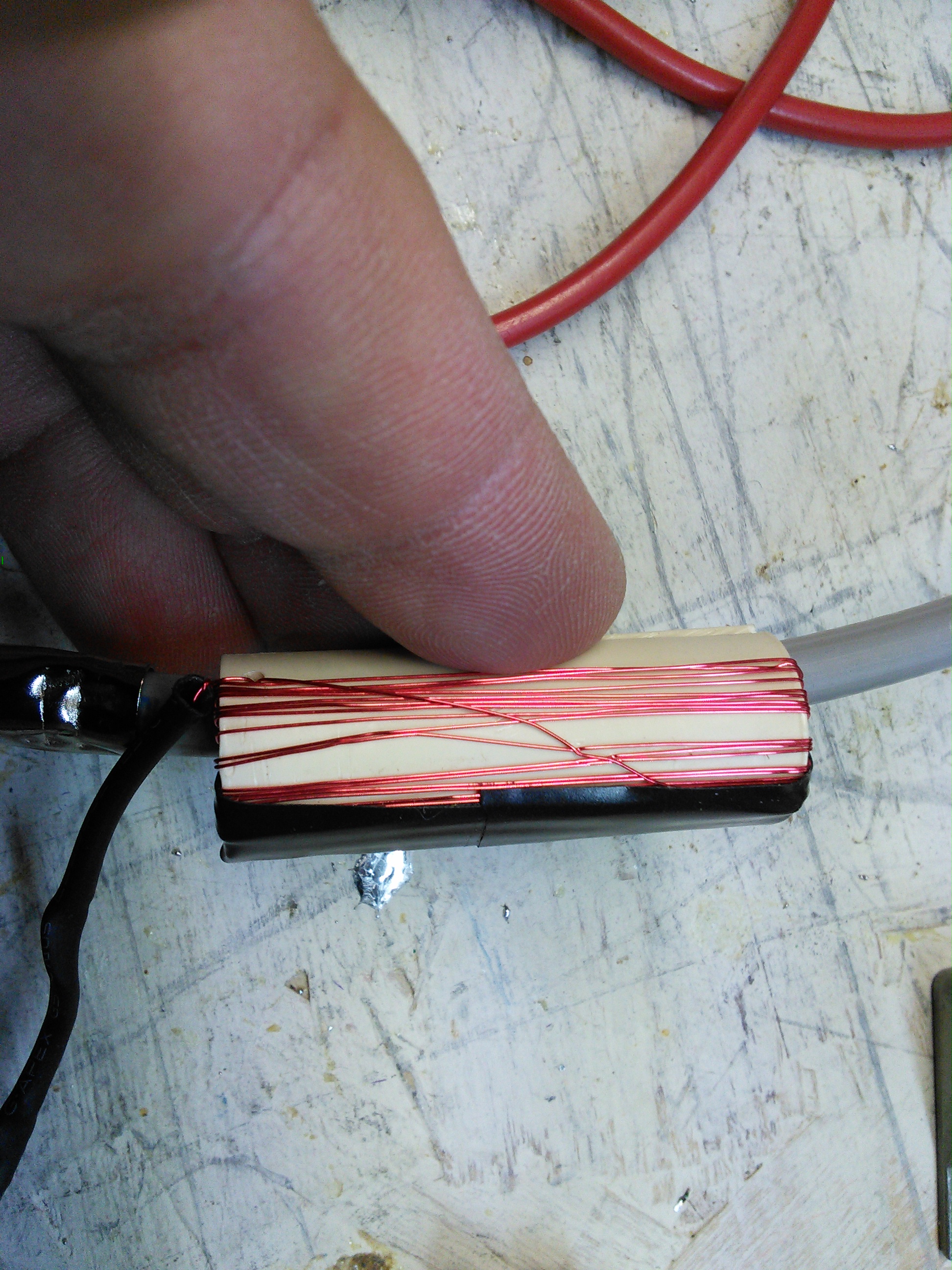
I recently had the need to check a transceiver to ensure that it was on-frequency. This is easiest done with a frequency counter, which is included in an MFJ Antenna Analyzer. I use an inductive coupler made from some coil wire around a small (1/2 inch) piece of CPVC, with the coil connected to a BNC connector.
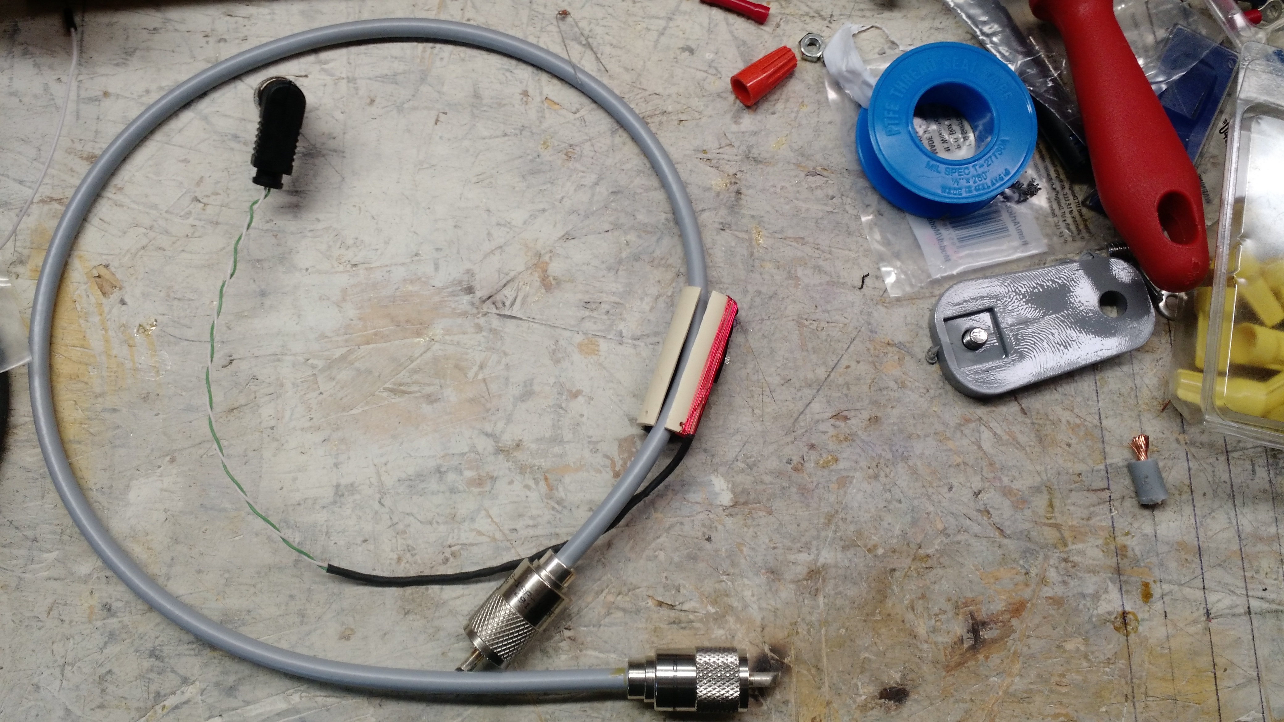
Inductive Coupler
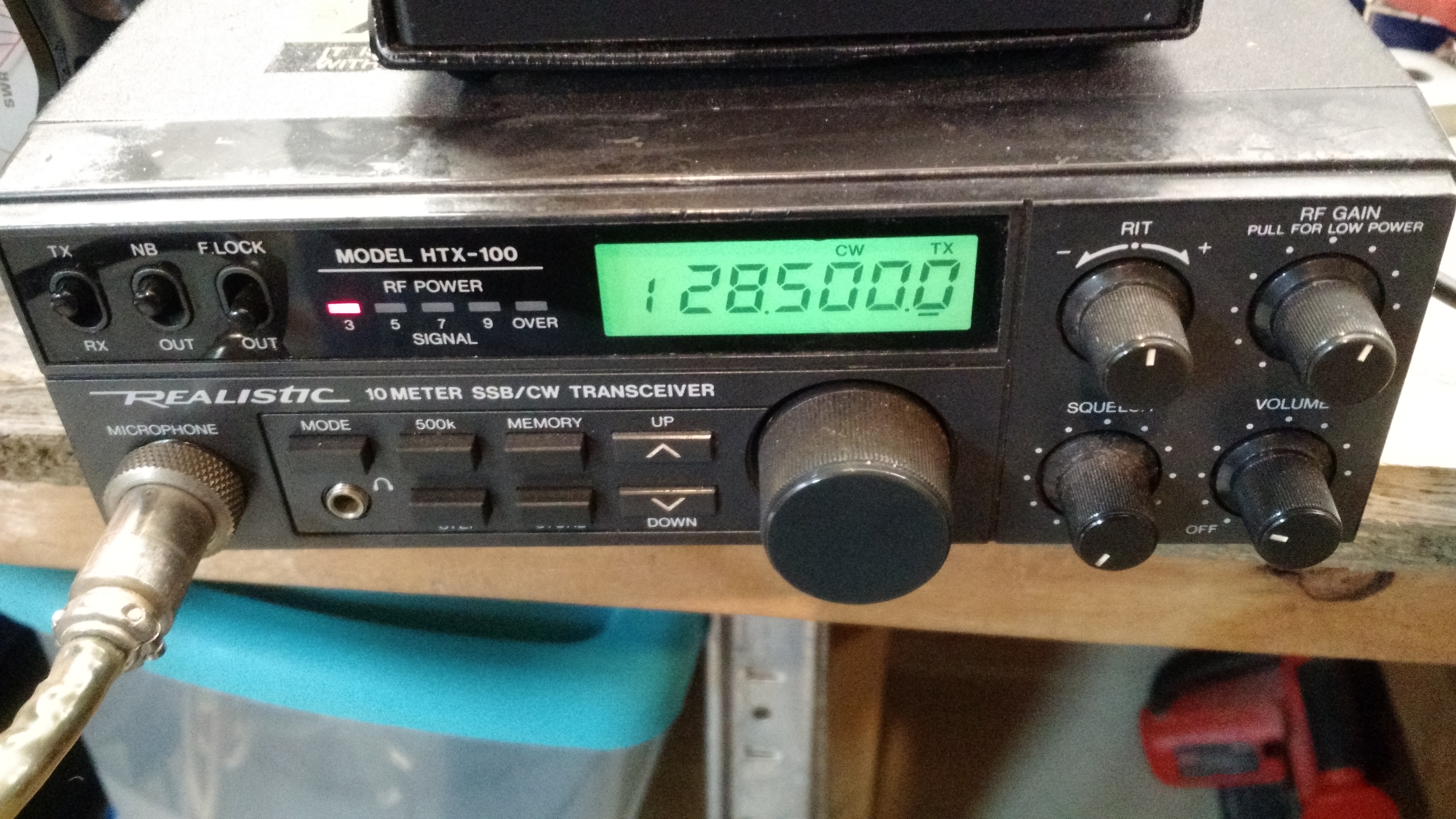
Radio set frequency (28.5 MHz)
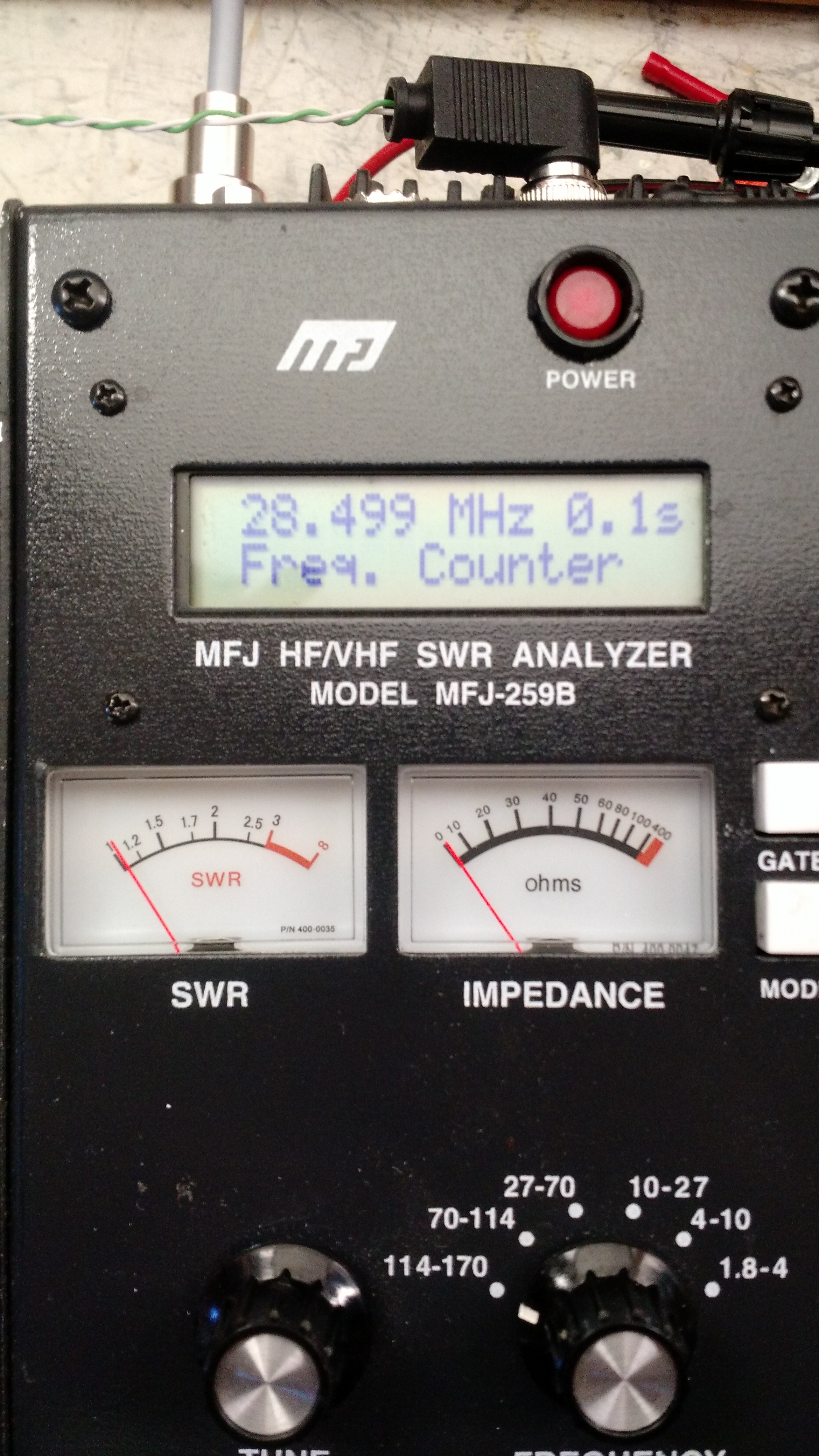
Frequncy (28.499 MHz, or close enough considering the potential error in the antenna analyzer)
-73-
One of the things I was looking into is a digital compass module. These are modules that return a direction it is pointing relative to magnetic north.
I started by using the Bus Pirate to access and read the module. I did that as below:
m <– for menu
4 <– for I2C
3 <– for 100KHz
I2C>(1) <– I2C Address Search
Searching I2C address space. Found devices at:
0x3C(0x1E W) 0x3D(0x1E R)
I2C>[0x3c 0x00 0x70] <–Set measurement mode to 8-average, 15Hz
I2C START BIT
WRITE: 0x3C ACK
WRITE: 0x00 ACK
WRITE: 0x70 ACK
I2C STOP BIT
I2C>[0x3c 0x01 0xa0] <– Set gain to 5
I2C START BIT
WRITE: 0x3C ACK
WRITE: 0x01 ACK
WRITE: 0xA0 ACK
I2C STOP BIT
I2C>[0x3c 0x02 0x01] <– Set to single-measurement mode
I2C START BIT
WRITE: 0x3C ACK
WRITE: 0x02 ACK
WRITE: 0x01 ACK
I2C STOP BIT
I2C>[0x3d r:6] <– Read 6 bytes
I2C START BIT
WRITE: 0x3D ACK
READ: 0xFF ACK 0xFD ACK 0xFF ACK 0x98 ACK 0x00 ACK 0x5F
NACK
I2C STOP BIT
This returned 0xFF, 0xFD for X, 0xFF, 0x98 for Y, and 0x00, 0x5F for Z. This is Twos Compliment Form, which is best explained by this Stack Overflow Community Wiki.
X Coordinate (0xFF): Binary 1111 1111 + 0xFD: Binary 1111 1101
Y Coordinate (0xFF): Binary 1111 1001 + 0x98: Binary 1001 1000
Z Coordinate (0x00): Binary 0000 0000 + 0x5F: Binary 0101 1111
Ultimately, this is where I stopped. I know it works, I have some ideas on how changes affect it. Now on to an Arduino.
Arduino Micro Setup
I plugged this into an Arduino Micro on a breadboard as below. The 5V, ground, pin 2/SDA, and pin 3/SCL were connected as shown (note that the compass on the left can be ignored – I have two and they are both in the breadboard just to keep them somewhere safe).
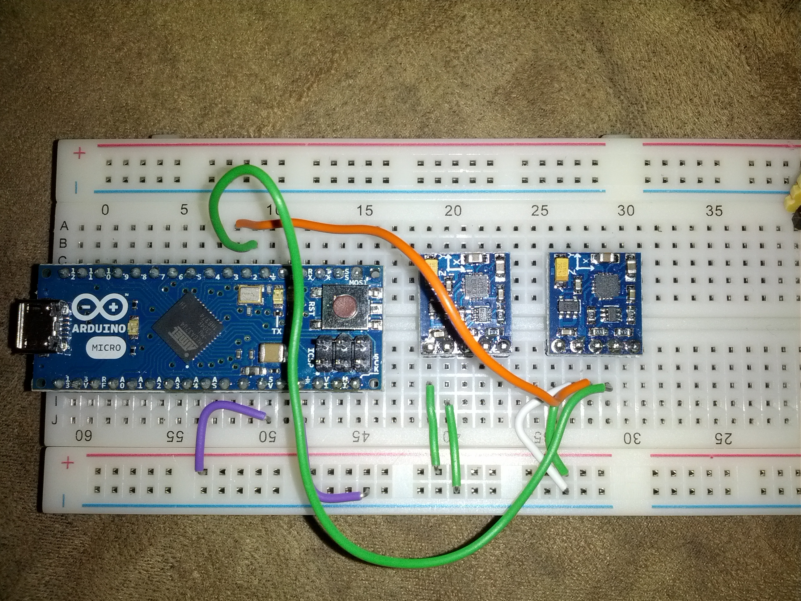
One of the more difficult parts of this is ensuring you’re in the correct pins on the Micro – the numbers are small and not centered on the pin.
The code is below. I started with code from Sparkfun and modified it as necessary.
Right now, this is functional. There will be more to come.
-73-
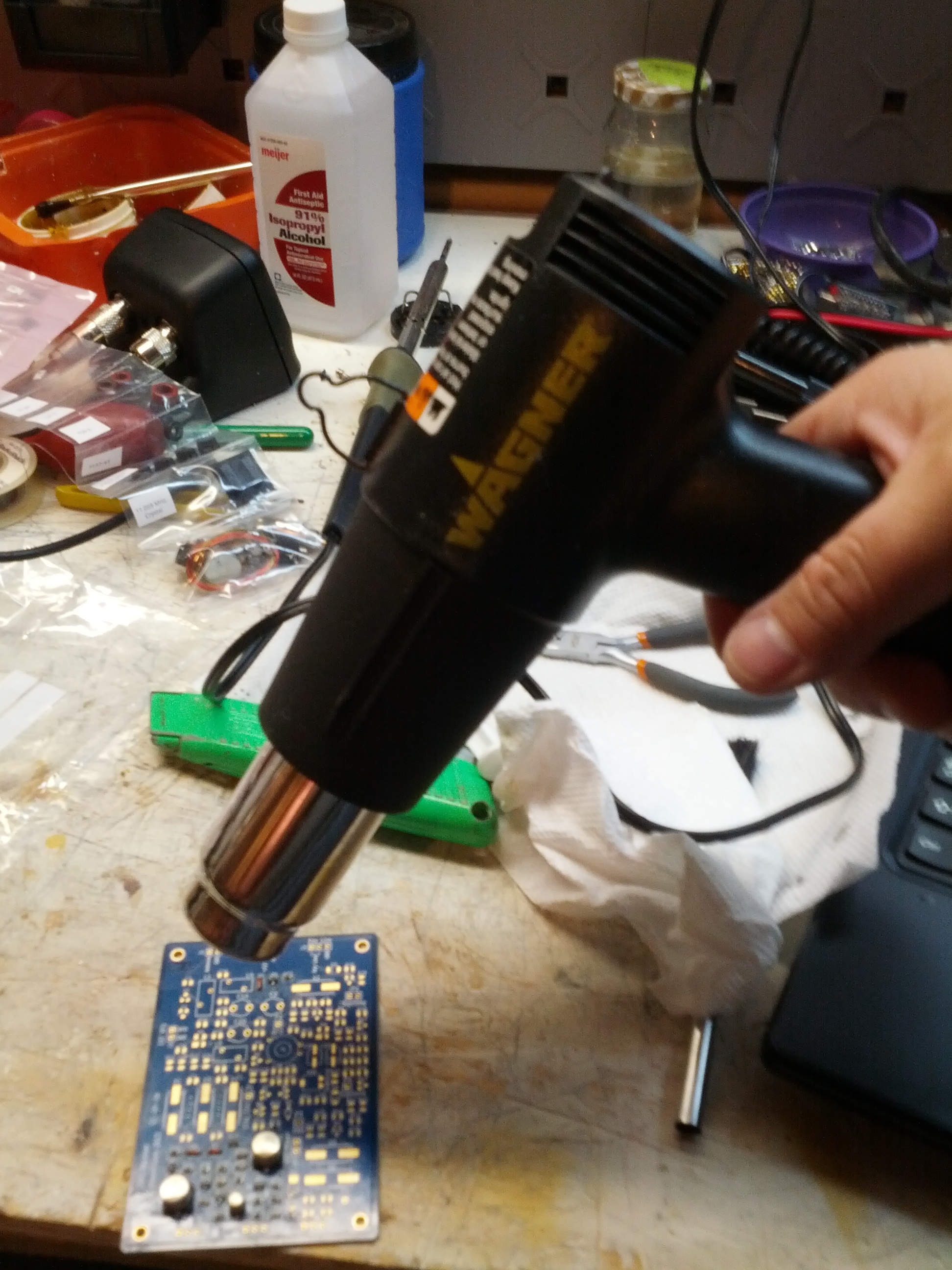
Thanks to the good service of UPS (that’s with one S, not that other group that leaves my parts sitting somewhere in Chicago for three days), I am now the proud owner of a solder station.
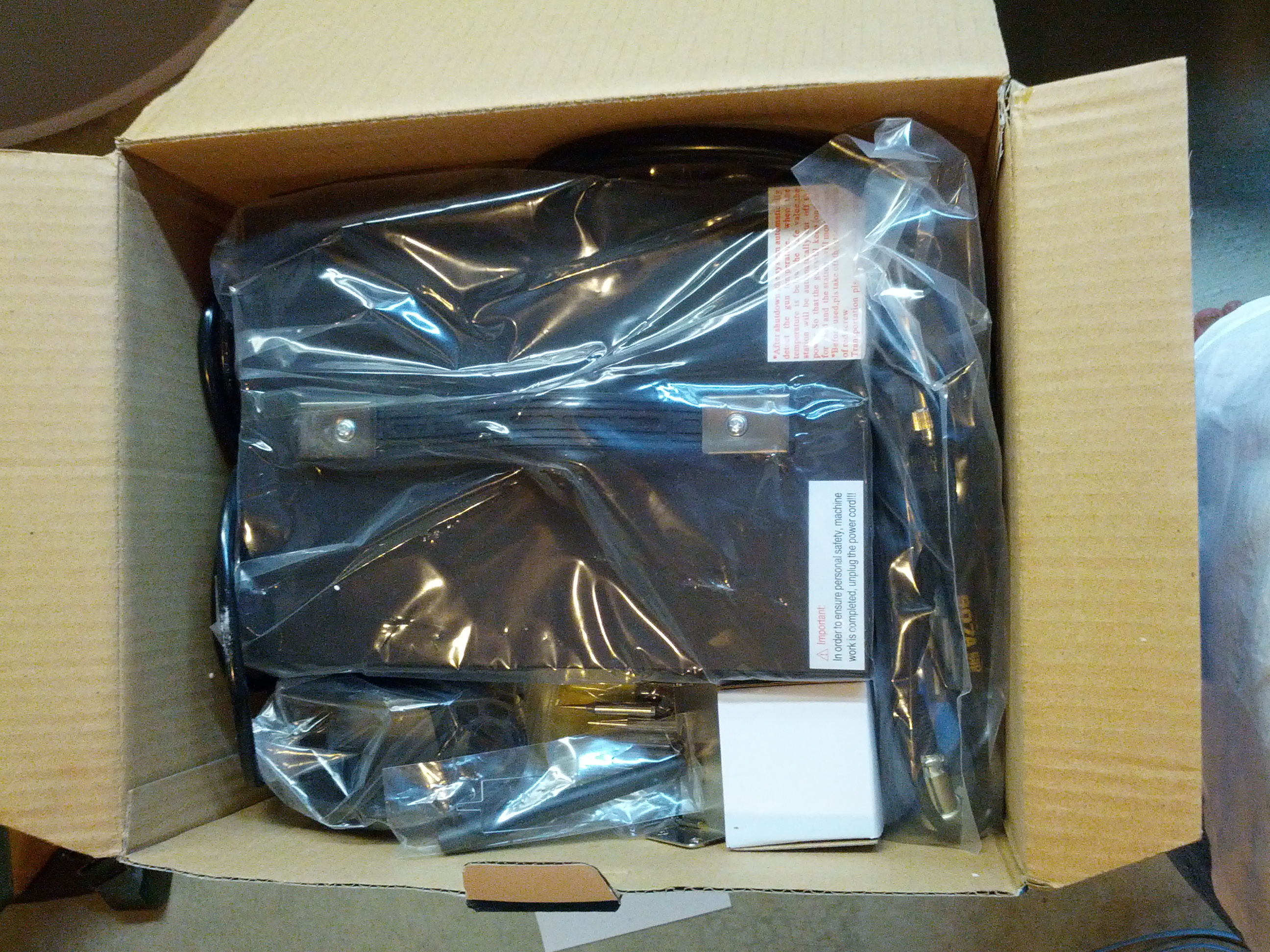
Unboxing.
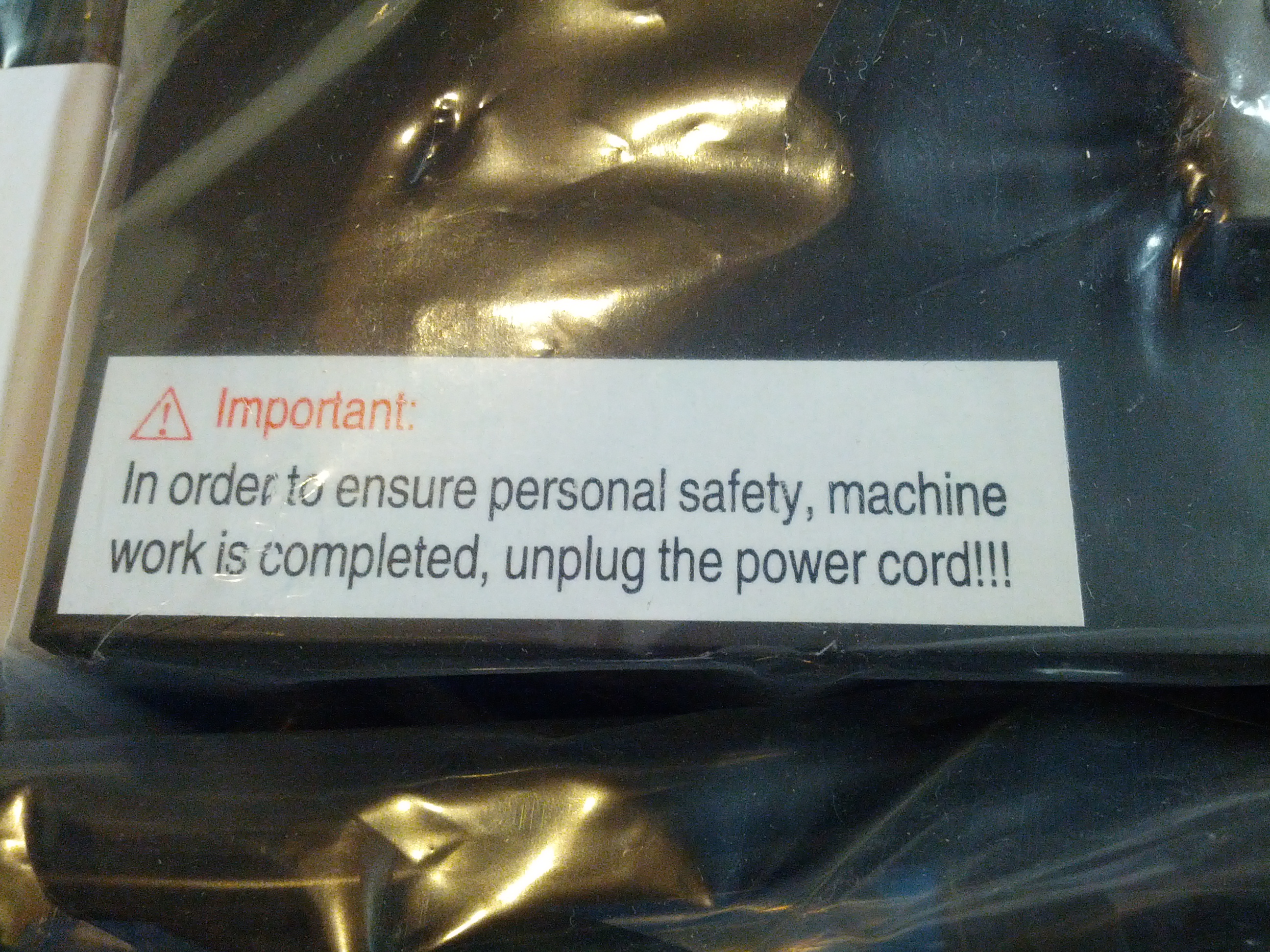
“In order to ensure personal safety, machine work is completed, unplug the power cord!!!”
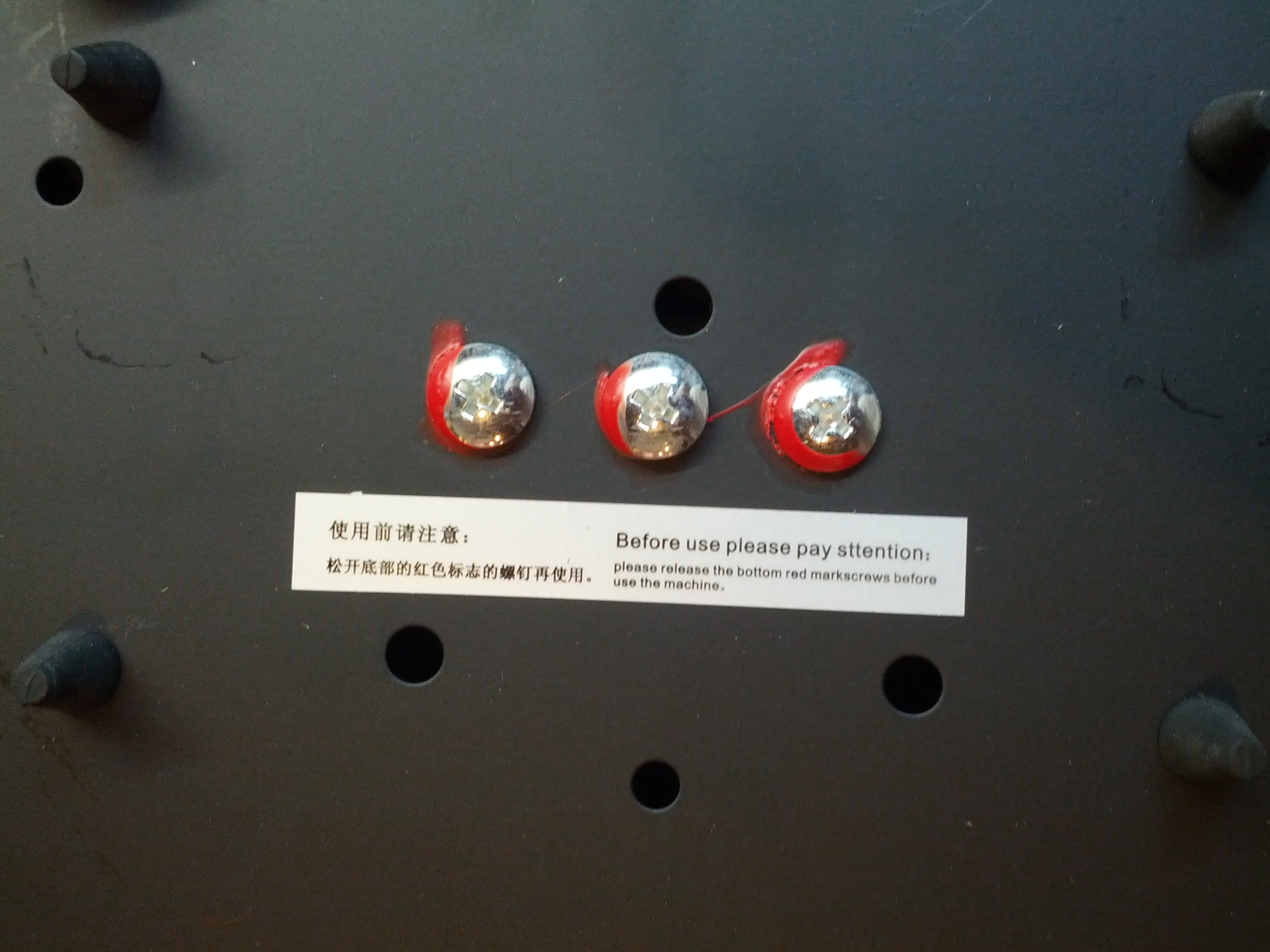
These screws have to be removed. “Before use please pay sttention”.
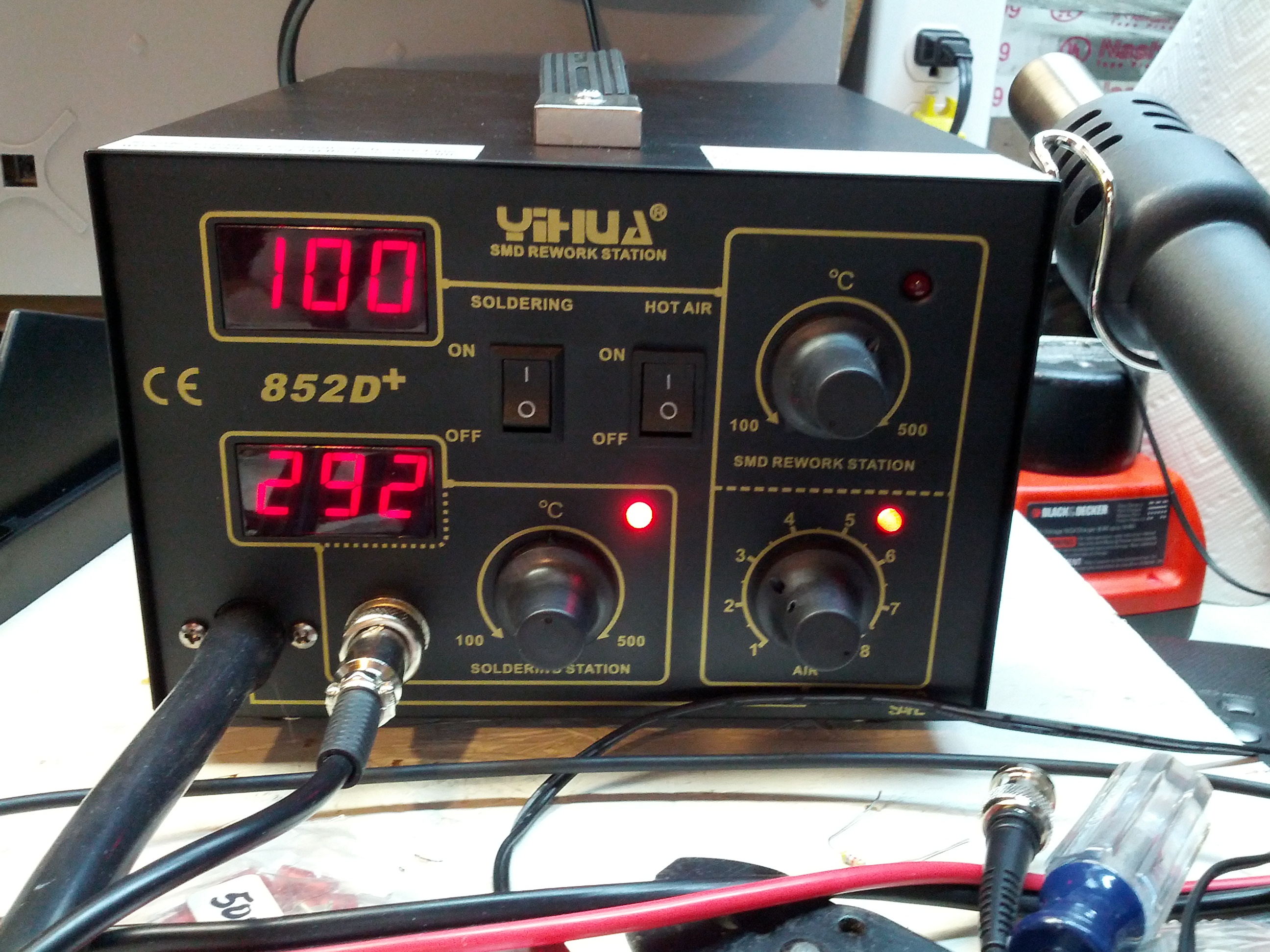
It works!
The sound from it is not too loud with the blower on, and of course when the blower is off there is no noise. It heats up VERY quickly, too. I’m used to my cheap old Radio Shack pencil iron taking 5+ minutes to heat up, and this heated up in about 30 seconds.
The temperatures are in Centigrade, so it’ll be something to get used to, but no big deal. And it was $50 via eBay (the link now goes to a more expensive item by the same seller).
-73-
I built an iGate.
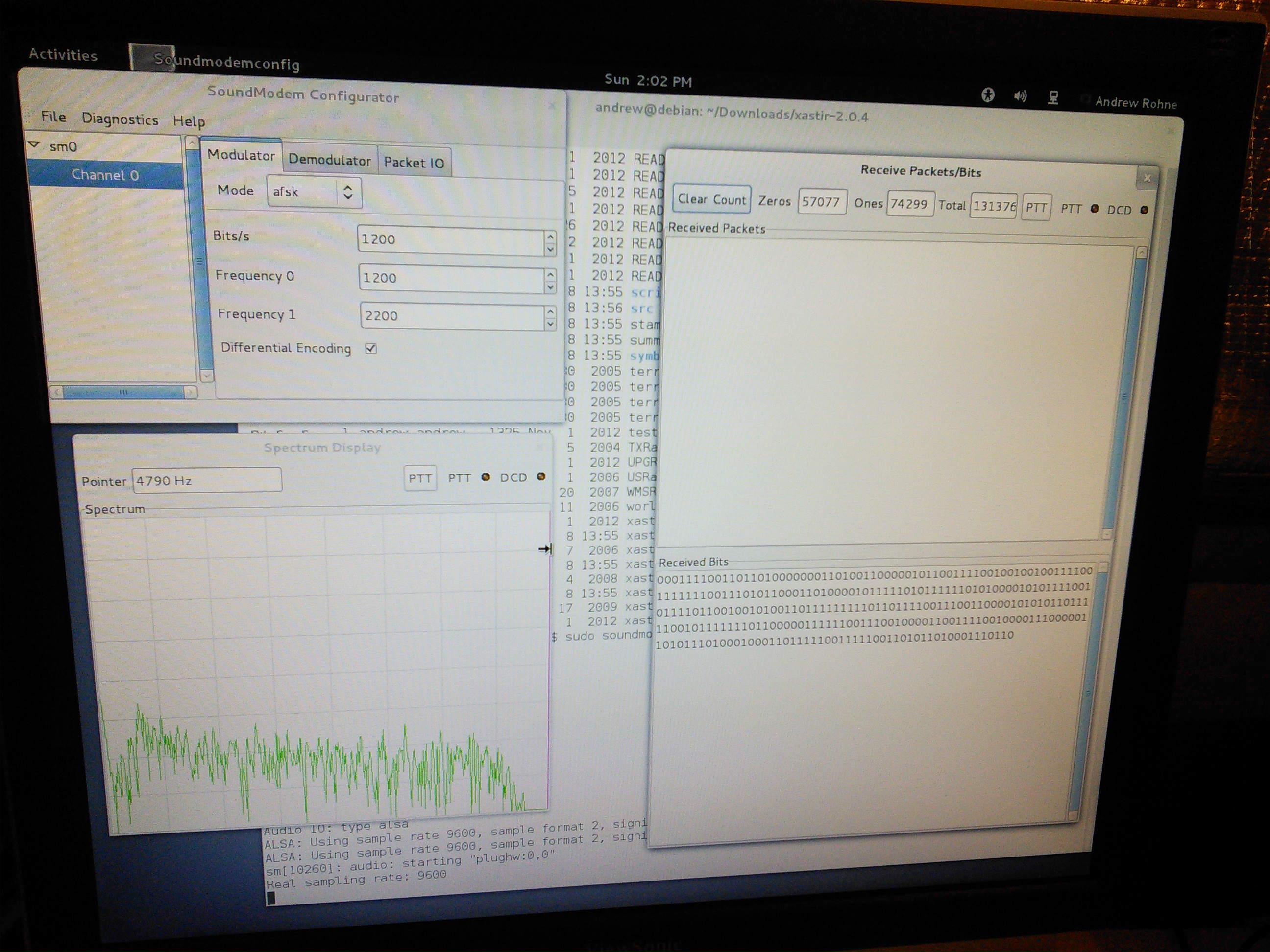
I basically used the instructions from KB9MWR, although aprsx was giving me fits. I have soundmodem running on Debian (it’s much easier to get it working there than Ubuntu), and the latest aprsx compiled locally.
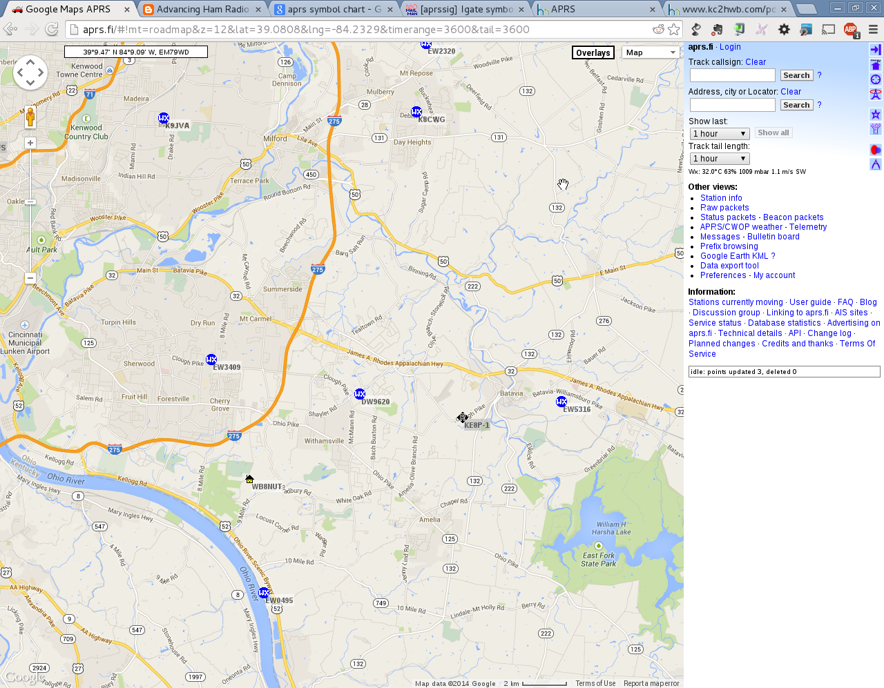
Hopefully by the time the evening rolls around, more will fill up this map gated by me.
Note that my location on the map is near, but not at, my house (not that I’m not really hard to find, with the magic of ULS/QRZ and Google Street View).
You can see the stats on aprs.fi. At the time I’m finishing this post, I’ve only gated 6 stations through and they are only digipeaters and weather stations. I have seen position packets through, but I don’t know if they are not being gated or if they are but APRSIS isn’t sending them because they are duplicates.
Either way, coverage on SR 32 (a high traffic highway) and SR 125 (a high traffic roadway) now have some coverage, and it looks like a local nearby digi is down for now (the owner has indicated in a blog post that he’s moved, so it may be back sometime).
-73-
Despite working at the food booth for the Milford Hamfest, I did get some time to get into the boneyard. I came back with a few things.
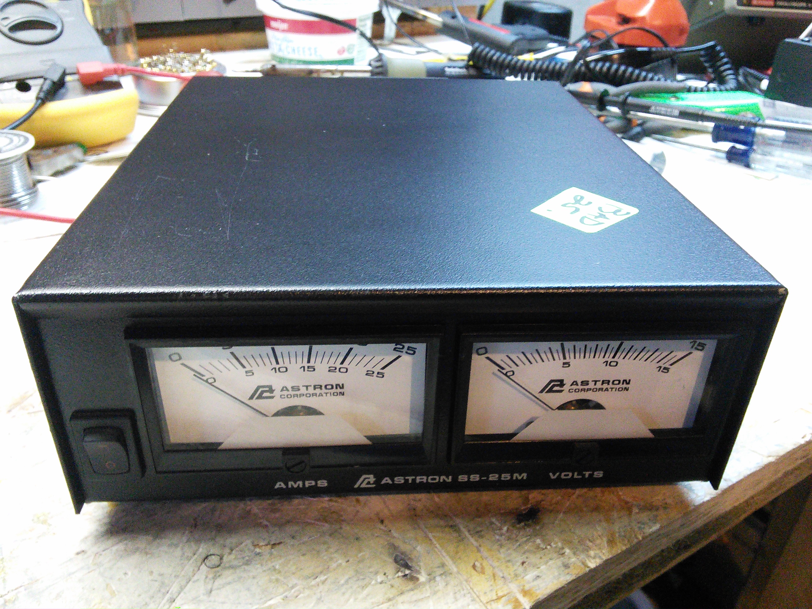
Astron SS-25M. Yes, the price sticker says “Bad”. No power output. It can be fixed – Astron makes some good products, and I’m sure I can find the schematics online.
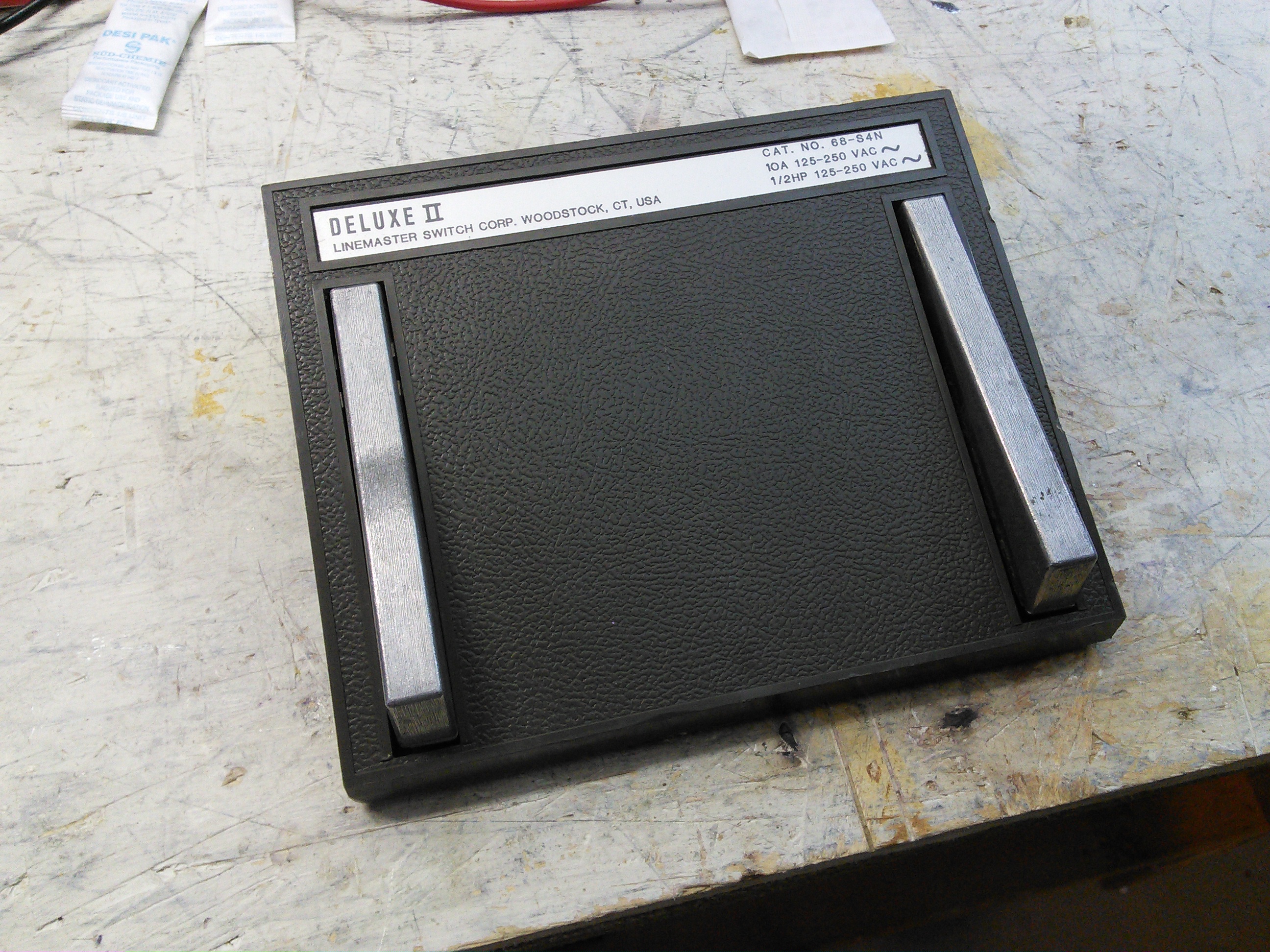
Footswitch. Dear reader, you didn’t think I’d use the wooden one forever, did you? 🙂
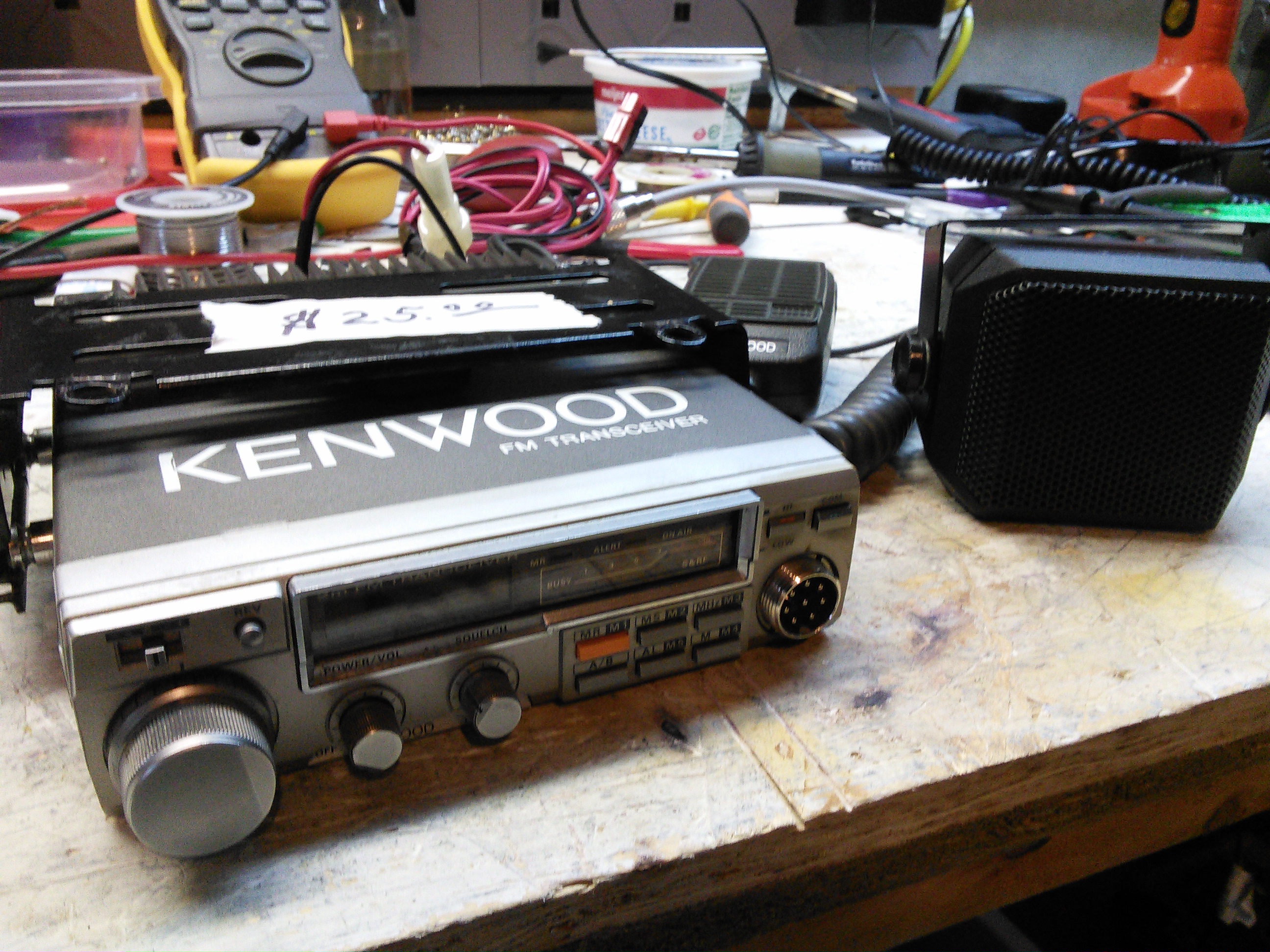
Kenwood TM-201A. Works, but has quirks (some may be by design – like the fact that I have to use an external speaker!). Power output was 6 watts, although I didn’t play with the power level switch to see if it would go up to 25 watts. I do like the slide-out bracket it uses.
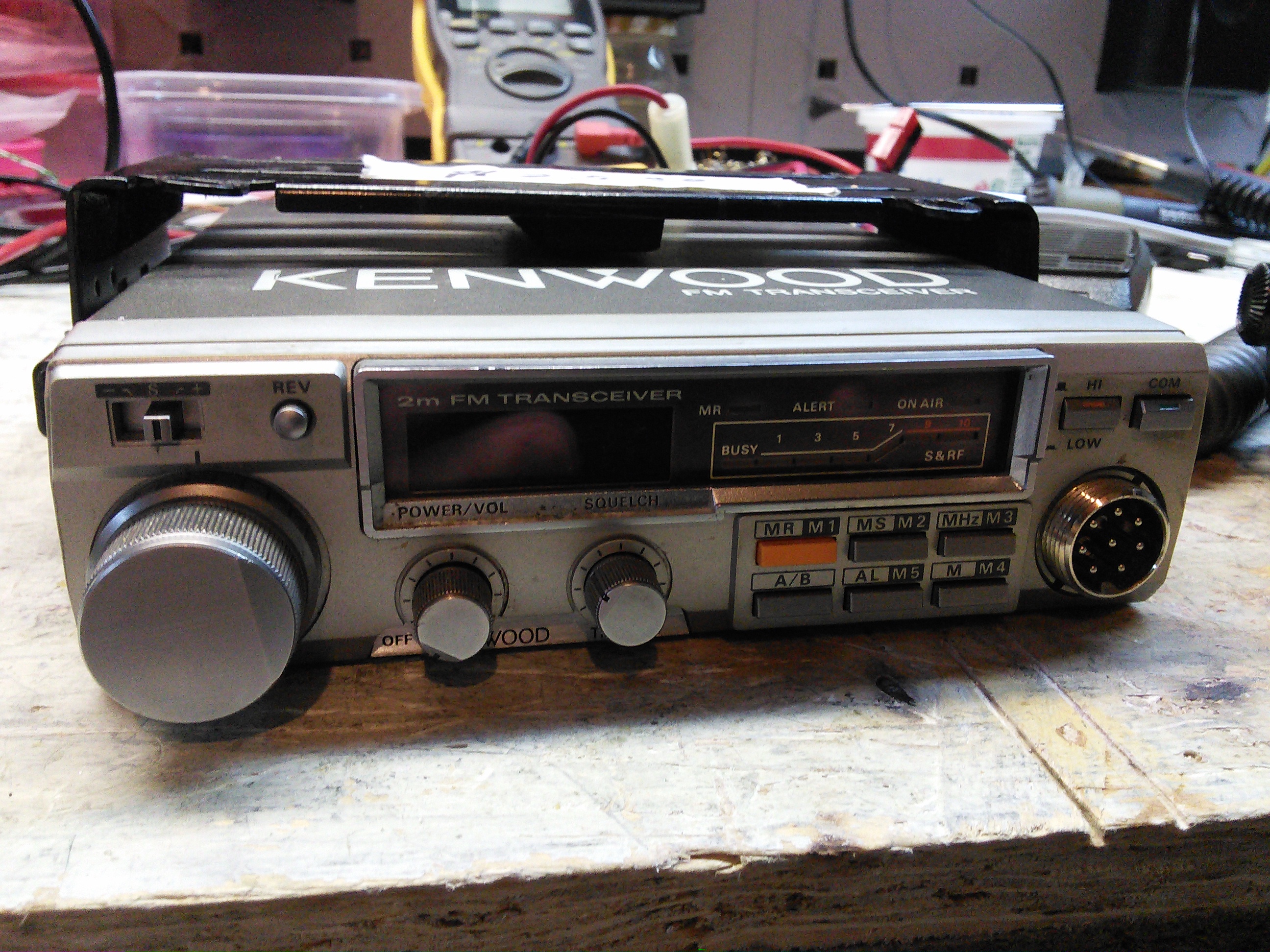
Another view of the Kenwood.
AEP PK-232 Packet TNC.

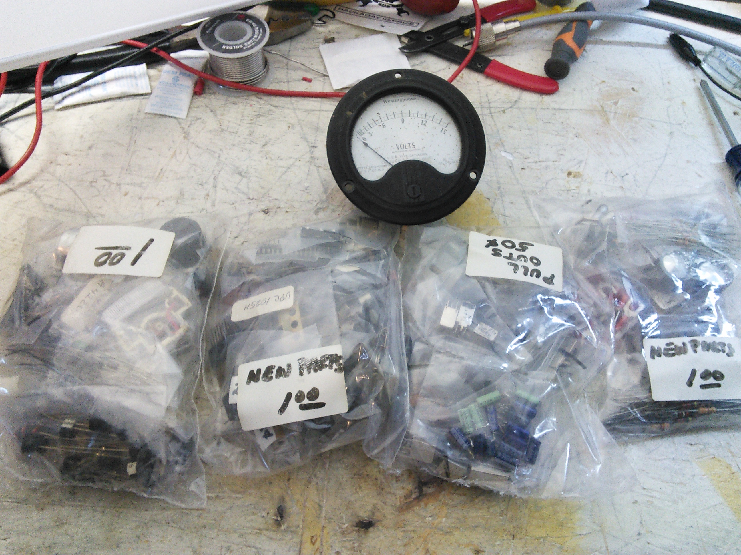
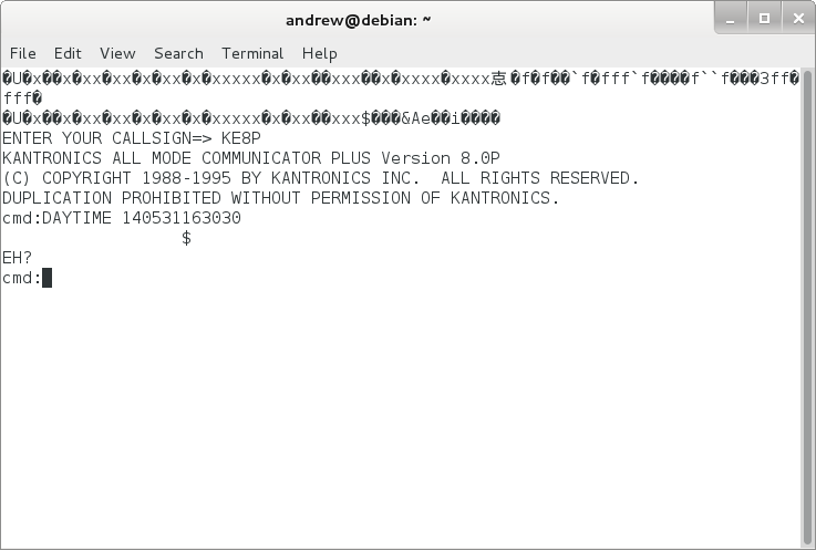
Parts. I looked through several bags and picked ones with parts I really want. The meter was partly to round up to $4, although I’m sure I’ll use it, too.
Not a bad haul.
-73-
I worked a little more on the IC-706 Friday night and located a bad ribbon cable to go along with the bad filter. I sent an email to Icom in the wee hours of Saturday morning, so I’m sure I’ll hear from them on Monday (or they’ll hear from me on Monday, one or the other). Since I’m waiting on parts, I moved that aside for getting into possibly building a packet station.
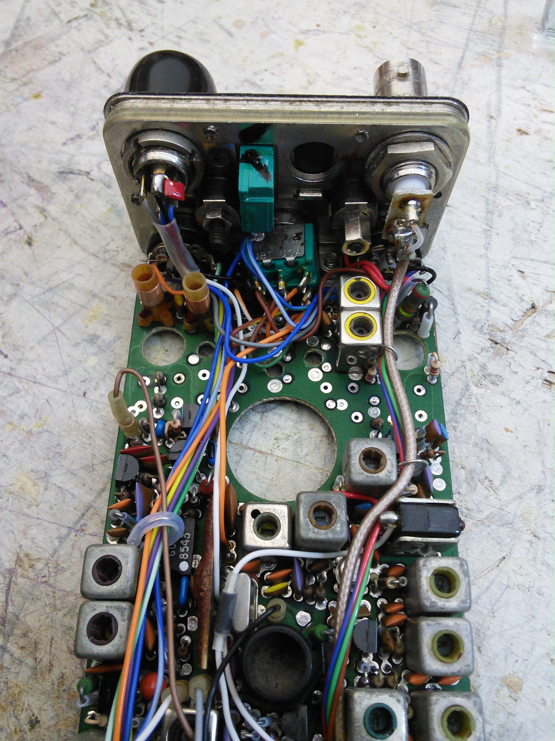
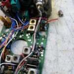
I started with a box I bought at a hamfest late last year. The part of the box that I saw first was a TinyTrak3 chip inside. I saw a Motorola commercial HT second.
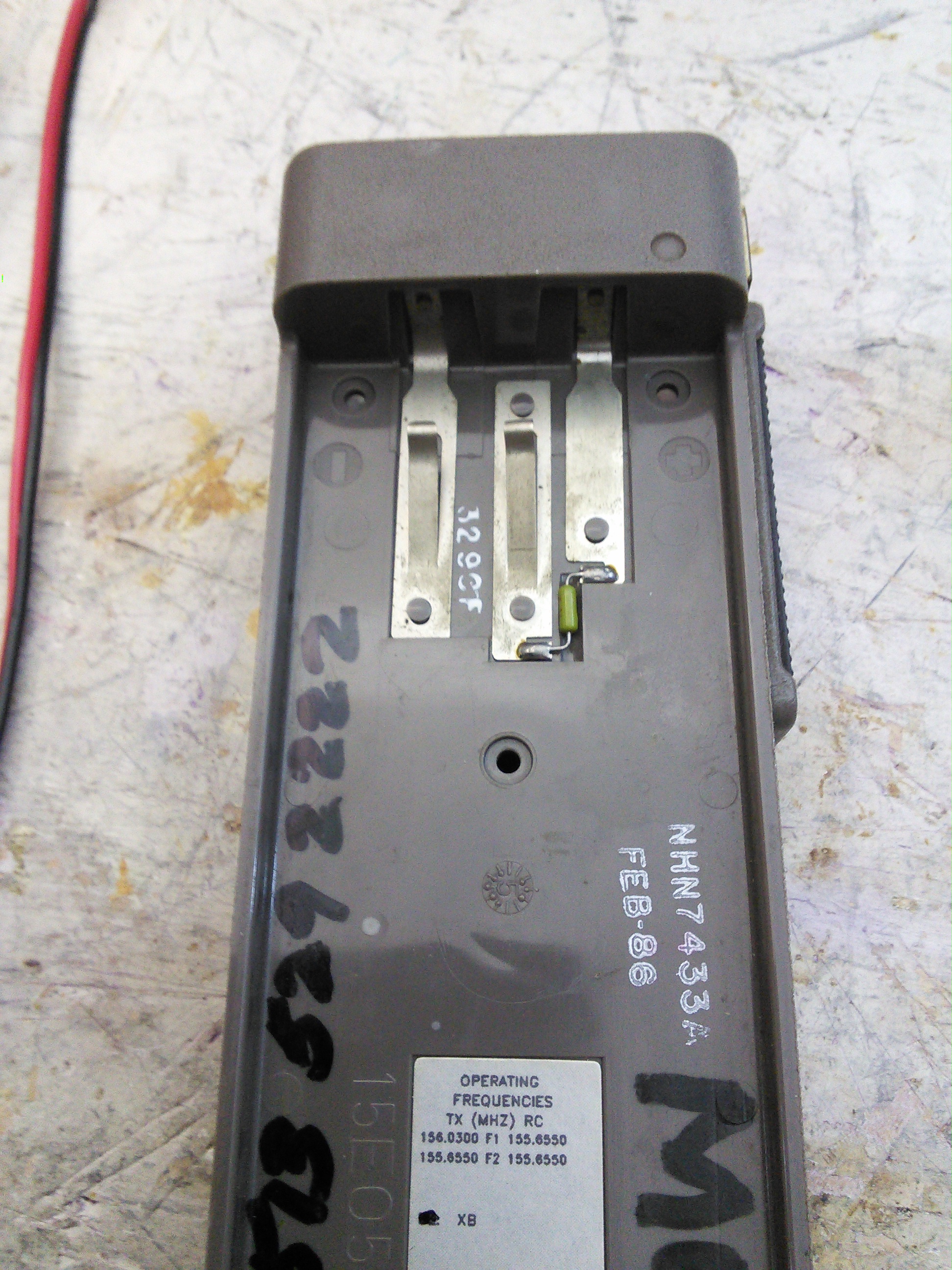
So I got into the HT, a Motorola HT90. It had a few minor challenges, like a short when I connected power to it (which was not with the battery, of course). Once I fixed that, I installed the two crystals (which one of the prior owners dropped about $75 on in 2002!). I had to tune it to transmit right on 144.390 (see the image in the gallery with my little test adapter). Once I did all that, I plugged it into the computer and installed and configured soundmodem.
Aaaaand… nothing. In fact, looking at aprs.fi, there was nobody in the area that was traveling. I left it on to (hopefully) get a few receptions on it.
-
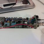
- Internals.
-
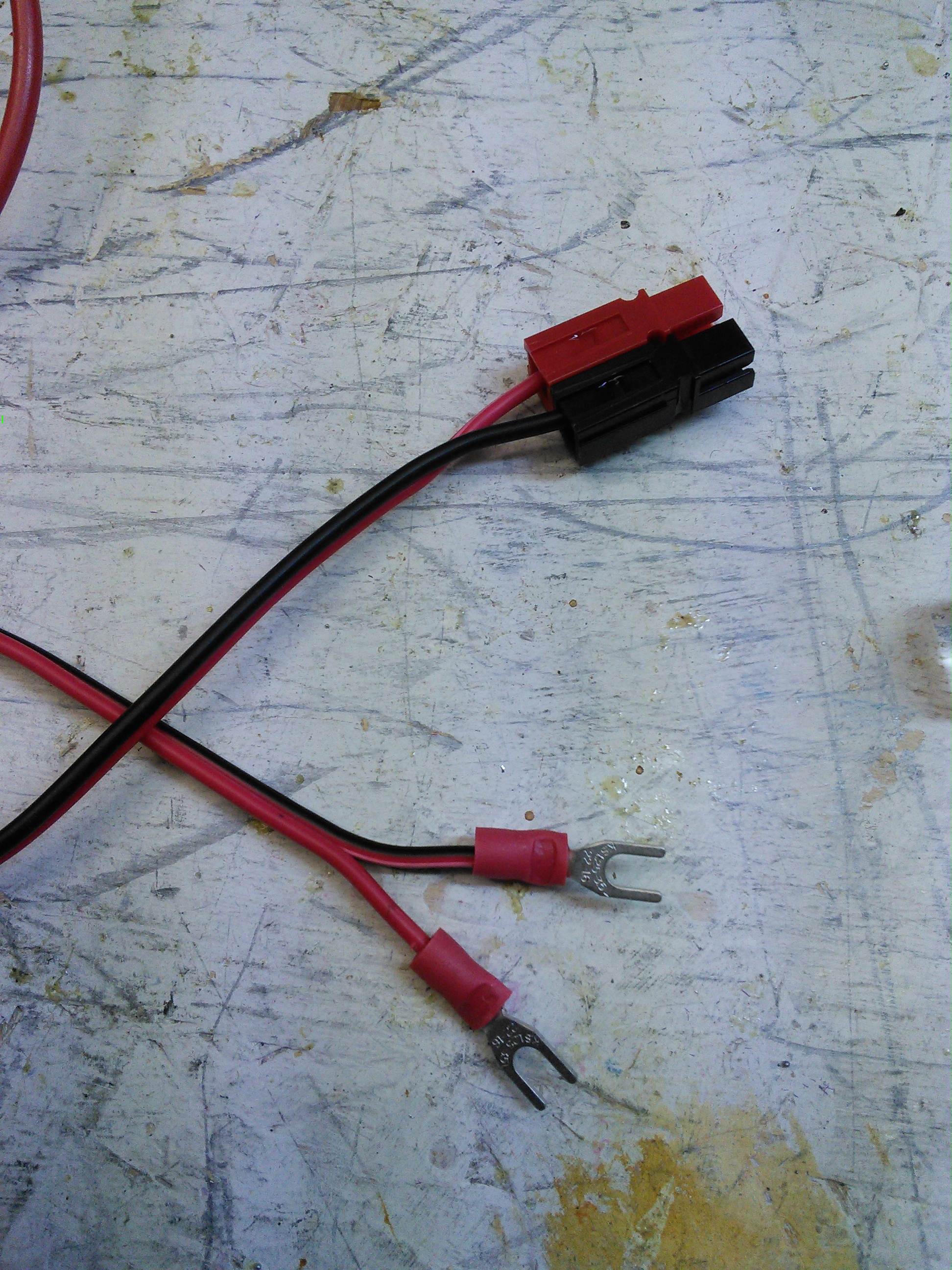
- The red wire is the positive power lead.
-
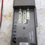
- This is the back. Fortunately, positive and negative are marked.
-
- New power lead.
-
- This is the new power lead connected to the radio.
-
- Test coil. This is a number of turns of magnet wire around a piece of CPVC pipe that is hooked to a BNC connector that attenuates the signal enough that 5 watts (and likely even 100 Watts) is safe to connect to my antenna analyzer.
-
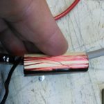
- Detail of the coil.
-
- The computer. Soundmodem works (and the waves stopped when I turned up the squelch or turned off the radio).
-
- This is the only packet picked up in over 24 hours. I think it is off frequency a bit.
-
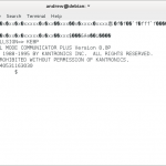
- This was my original try on a packet station – a Kantronics KAM+. I think it was affected by the Y2K bug.
-73-
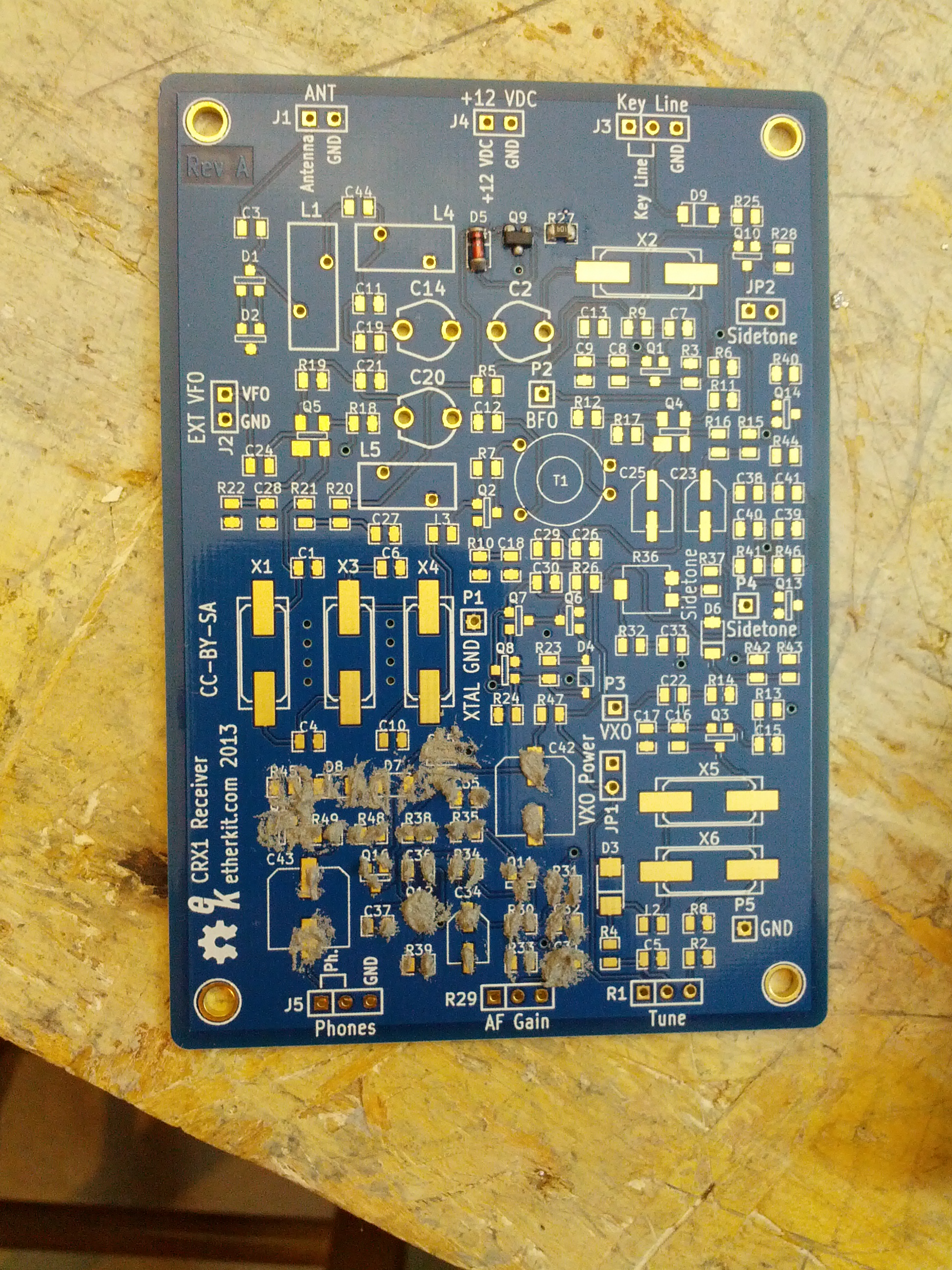
On the heels of NT7S announcing that he’s taking the red pill on Etherkit, I ordered a CRX1. I decided this would be a good chance to try reflow soldering with the solder paste I added on the last Mouser order I placed.
First off, on the kit. This is how things SHOULD be packaged, especially with SMDs.
If you can’t find it here, you’re either illiterate or it isn’t here!
Onto the build.
I used the syringe and a screwdriver to spread what was sometimes too much paste on the pads…
Then heated it up until I saw the components move into place (I have to admit that seeing the components move to the correct place is AWESOME!) and the solder looked fully heated.
The end result looks like this.
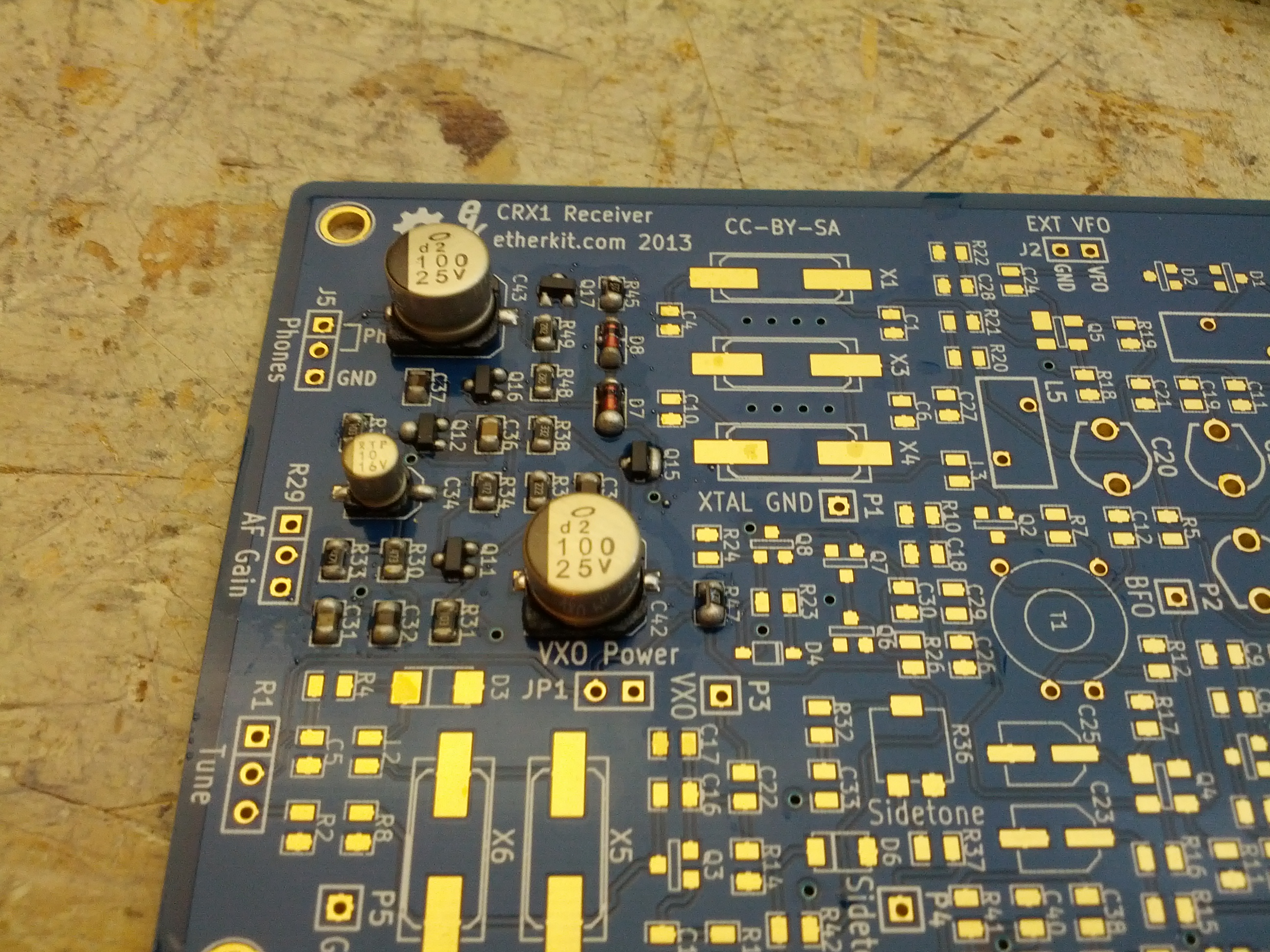
Lesson learned: tools made for removing flooring are NOT meant for electronics! In the pic, the plastic bases for the electrolytics are starting to melt. That can’t be good; hopefully those caps didn’t get too hot. Also, it may have charred my workbench. Hopefully by the time this posts I will have purchased something better (like a real soldering station!).
I admit, I was being a fool and using the wrong tool.
This is the last of the series of using the Bus Pirate and the Bus Pirate Demo Board. This one is using the SPI EEPROMs. The board has two of the same EEPROM (well, one is SOIC, the other is DIP, but other than that, they’re the same).
Connections
The power connections for this are the same as the connections you’d use for an I2C device – ground and power (I used 3.3V) + pull-up to Vin.
The data connections are pretty simple because the Bus Pirate is marked with MISO, MOSI, CLK, and CS (Master In Slave Out, Master Out Slave In, Clock, and Chip Select) and the demo board is marked with MISO, MOSI, SCK, and CS (there is one difference, and the process of elimination fixes that!).
Writing and Reading to the EEPROM
There are two steps to write to the EEPROM – send a write-enable command and then write to it.
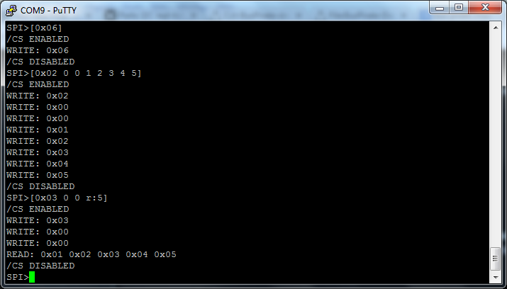
[0x06] – write enable command
[0x02 0 0 1 2 3 4 5] – 0x02 is write, 0 0 is the address to write to, and 1 2 3 4 5 is the data to write
[0x03 0 0 r:5] – 0x03 is the read command, 0 0 is the address, and r:5 means read five bits.
—
That’s it with the demo board! Expect that the Bus Pirate will make more appearances on this blog, though.
-73-