
I’ve been playing around with my BeagleBone Black quite a bit recently. It all started with one of my coworkers bringing in a rain gauge that we had collecting dust somewhere in an office storage room. I had been installing software to the BBB and ran out of space on the eMMC (internal memory) chip. So I tried to boot from an SD Card – the one I updated the BBB to the latest software with and still loaded with the image. It appeared to me that it maybe had been reloading the eMMC, but I couldn’t tell for sure. After around a half hour, I power-cycled the BBB. Bad news, it wouldn’t boot. I don’t have the correct HDMI cable, and I’m at work, so my resources are pretty limited.
Enter the FTDI port on the BBB. Enter the fact that I don’t have an FTDI cable at the office. D’oh!
But I have a few Arduino Unos.
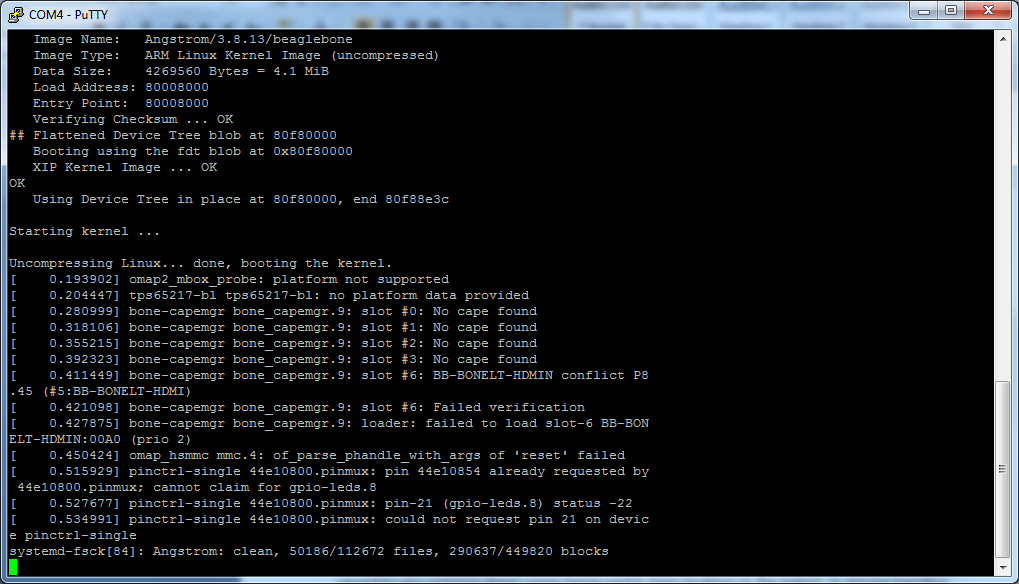
I wondered, and then quickly looked on the Internet to find a page on Instructables that describes how to use an Arduino as an FTDI programmer. I then looked at a reference for the pinouts. A page at Circuitco has the pinouts that seemed like they’d work – ground, RX, and TX. I hooked them up and…
It gets a little bit more MacGyver-ish. I have only a small box of jumper wires at the office, a few shield headers, and a breadboard…
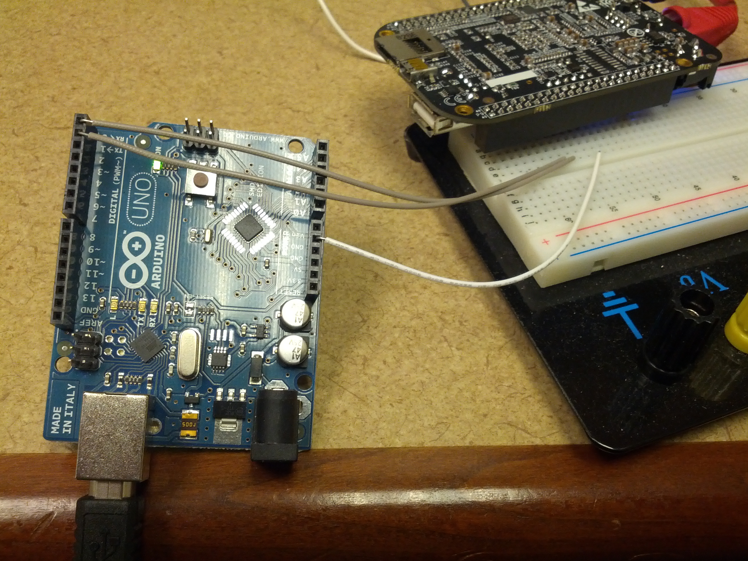
This is an overview of the setup. The Arduino RX, TX, and Ground are connected to a breadboard that has a shield header that connects to the BBB’s FTDI port.
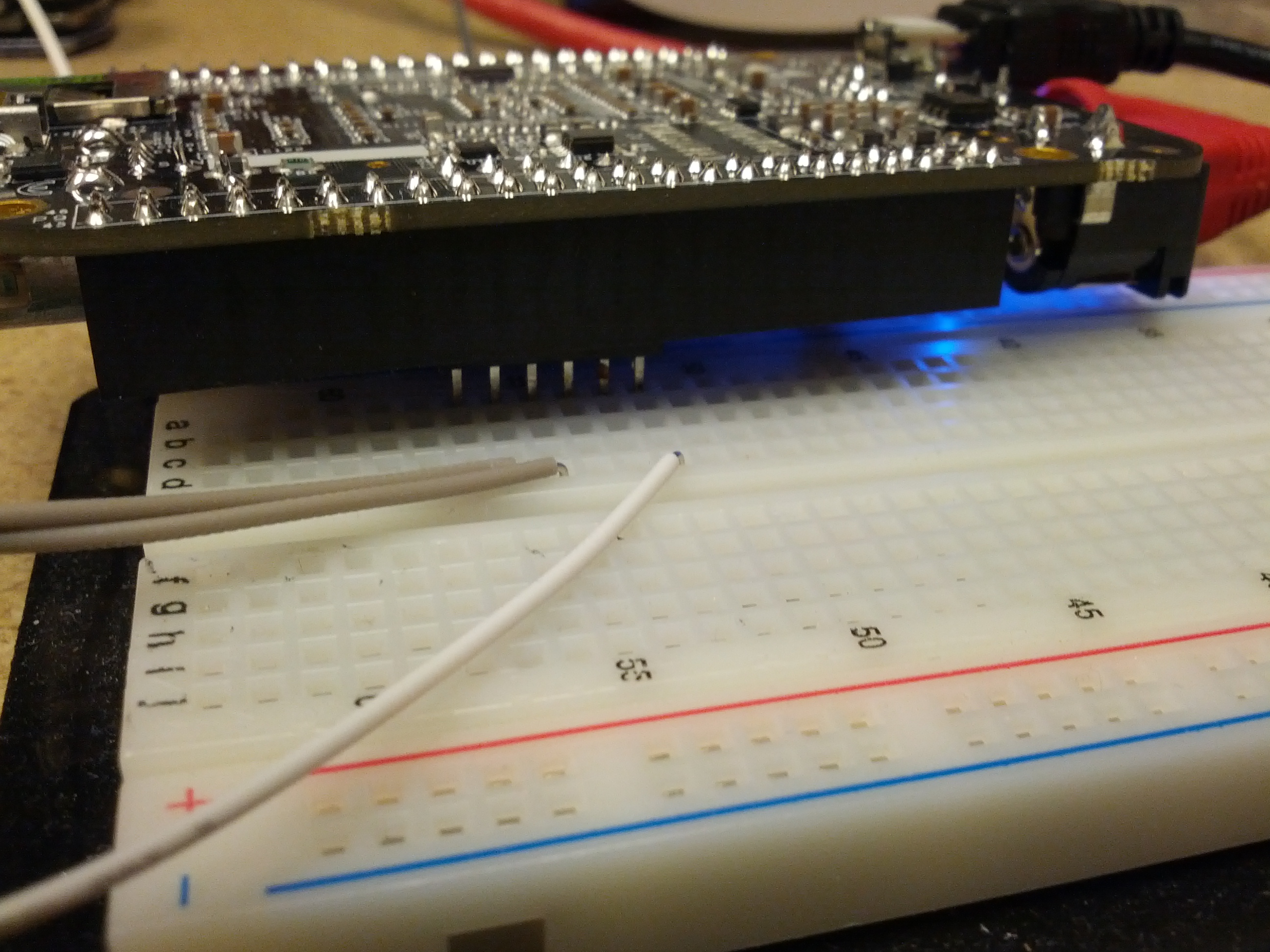
This is the connection between the breadboard and the BBB.