
For anyone on the Amateur Repairs (*cough* yahoo *cough*) group or who follows me on G+, YouTube, or Twitter, you’ve likely seen posts related to my IC-706 mkIIG. I’ve pulled the radio out of service because of problems primarily on VHF-FM (at least it seems that’s where the problems are at). In fact, since early December, I’ve been sporadic with transmitting with it, and I haven’t transmitted with it at all since mid-January.
The problem I’m having is extreme static even with very strong signals. I’ve checked the likely (hopeful?) culprits of power cords and antenna connections. Since things seem to be fine on those – I’ve tried two power cords and three power sources and two different antenna setups – I’ve moved on to checking internals.
My first check was for anything obvious. Like this, this, or even this. Nothing. I don’t know if I should say “fortunately” or “unfortunately”.
My second check was to poke around inside. I first looked at some of the audio waveforms at the NB test point and the WFM test point. Pretty interesting to see on a scope, and they didn’t react to volume (that’s a good thing, as this is likely before the audio amp!).
The Noise Blanker Test Point
(PS in the video above: yes, I’m checking that with an oscilloscope probe. It works, even if it isn’t necessarily ‘right’… or maybe it is, I don’t know).
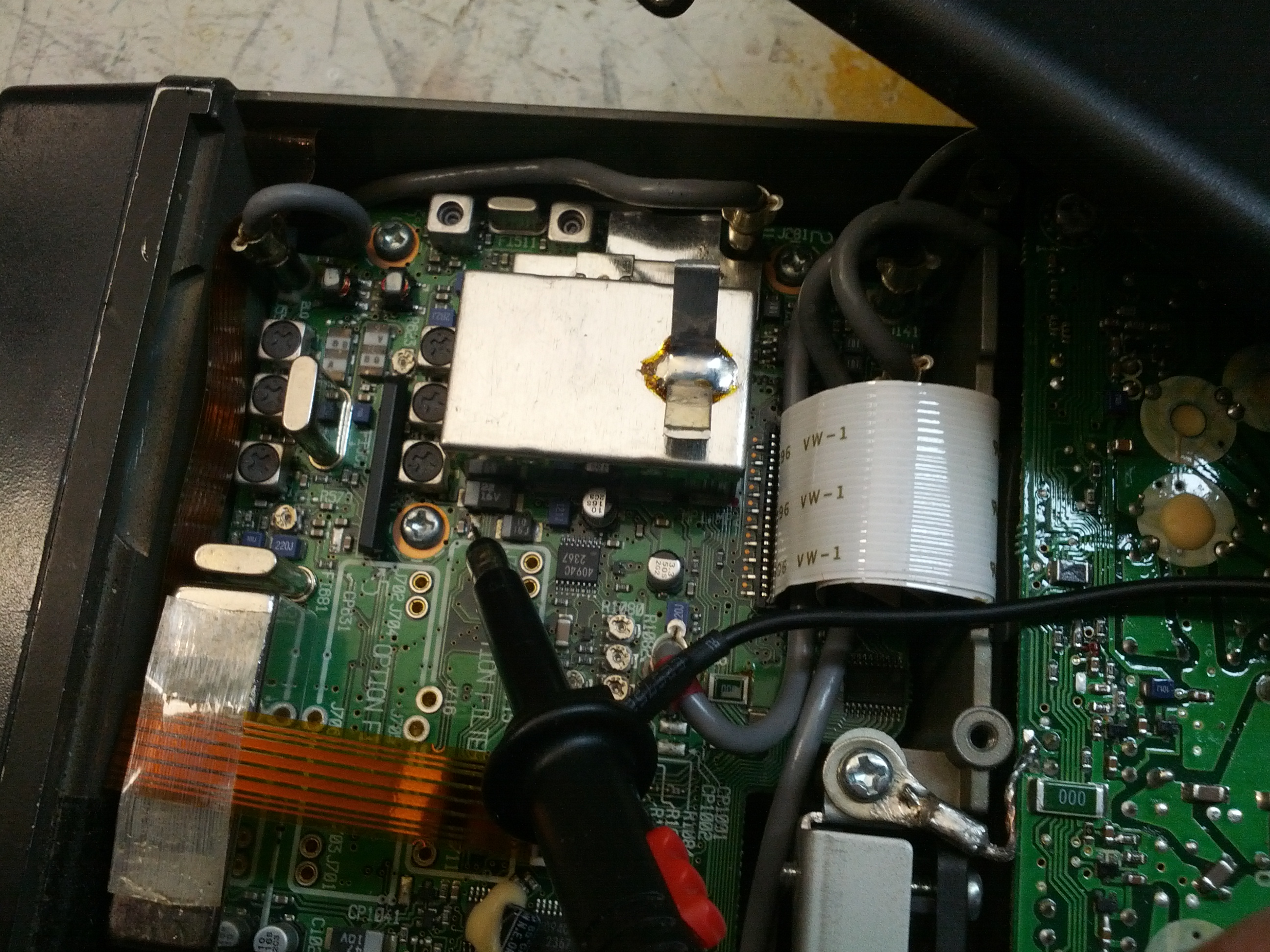
My second test was to do something more … practical. I know from some of the reading I’ve done in the ARRL Handbook, the owners and service manual for the rig, a video from Kenneth Finnegan (from The Life of Kenneth blog that I follow), and some comments from Mike M. on Google+ that maybe I should check the PLL board. And besides, checking stuff is easy, right?
This is the small battery of PLL tests.
The first check is the 60 MHz reference frequency. After finding and fixing a messed up power switch on my antenna analyzer and after checking it with the scope to ensure I wouldn’t blow up my analyzer, I probed it and found exactly 60.000 MHz. Good.
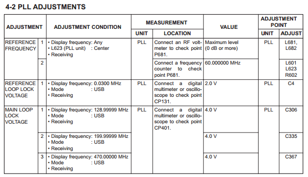
The second test was of the PLL Loop Lock Voltage. Initially, I found that it was around 300 mV. This was too far outside of the required 2.0 V at 0.03 MHz. I thought for a moment that it might be a typo, although those things NEVER happen…
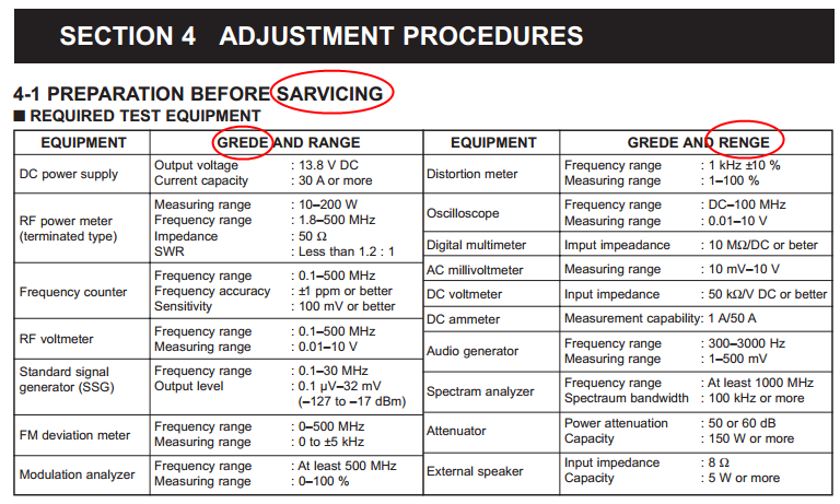
I’ve circled a few of the typos in this – not every one. Apparently I’m SARVICING this radio and I’ve been spelling GREDE and RENGE incorrectly all these years.
…and moved on to test the Main Loop Lock Voltage. It was far less than the spec 4.0 V on the first test (at 129.99999 MHz), so I didn’t continue tests.
After some replies to the post on the Amateur Repairs group, I tried again to recalibrate the PLL circuit and was able to do it. This was, of course, after I removed a shield to test two transistors. I’ve reinstalled it in the truck and so far, so good. But we’ll see. It could have been that the PLL was off causing weird errors that may have changed as voltages to the radio changed (it is mobile, after all), or it could be that something is still bad.
-73-