
My work has taken me down the road of using Raspberry Pis as data collection devices. This means I need to power a Raspberry Pi in the field. I’ve had trouble finding a reasonably-priced 12V to 5V USB adapter that I could easily and safely fit into a box with a RPi. So I designed one in KiCAD and built it. The design is on my work github account.
I’m ultimately designing something that will connect to a battery, and batteries can explode if mistreated. Testing is critical, as is circuit protection (the fuse). I’m envisioning this to be in a box on the top of a pole with a camera, so the lead going from the battery (which will likely be on the ground) will be fused in case the wire gets cut. This is critical for the same reason it is necessary in a car – to protect the battery from short circuiting should something happen.
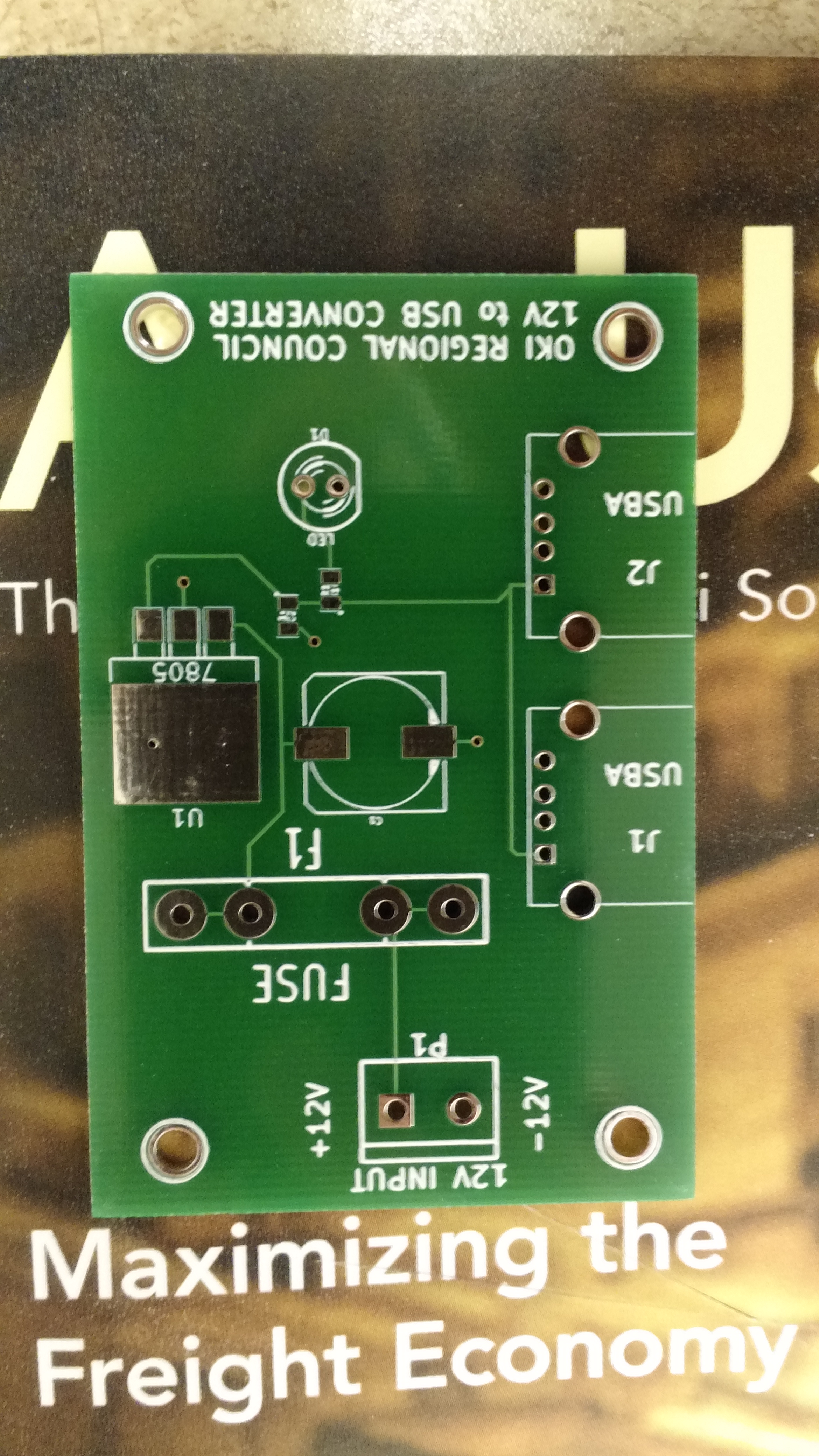
Empty PCB
Test fit components at the office.
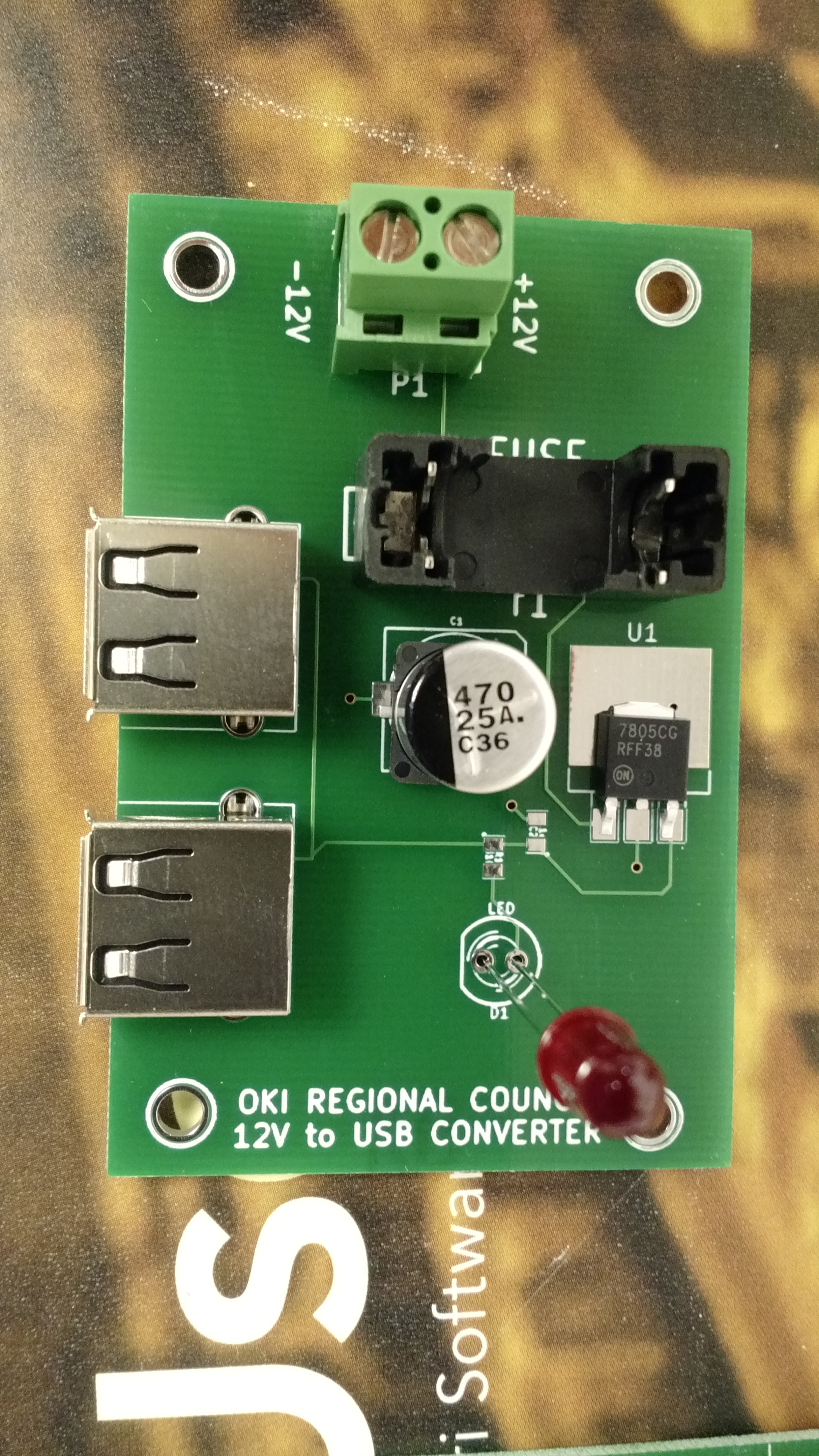
In putting these together at home, I tested these in every way I could think of, and assembly and testing went something like this:
- Solder SMD C2 and R1
- Test resistance from 7805 output to LED positive solder hole, should be 330 ohm (I used 330 ohm resistors instead of 310, since I don’t happen to have any 310 ohm).
- Test continuity from 7805 output to ground via connected to C2. Should show no continuity.
- Solder USB connectors and C1
- Test capacitance from 7805 input to to ground via near C1. Should show a reading (mine all showed around 1000 uF, which is high, but my understanding is that multimeters are notoriously bad at capacitance)
- Add input headers, fuse holder, and LED
- Test continuity between inputs – should immediately beep, and then drop to no continuity after capacitors charge
- Apply voltage, LED should light, all magic smoke should remain contained in devices
- Test voltage from 12V- to 7805 output – should be 5.0v (mine showed something like 5.007v)
The one thing I was unable to test was the actual USB output voltages, but it seems to me that they should be okay.
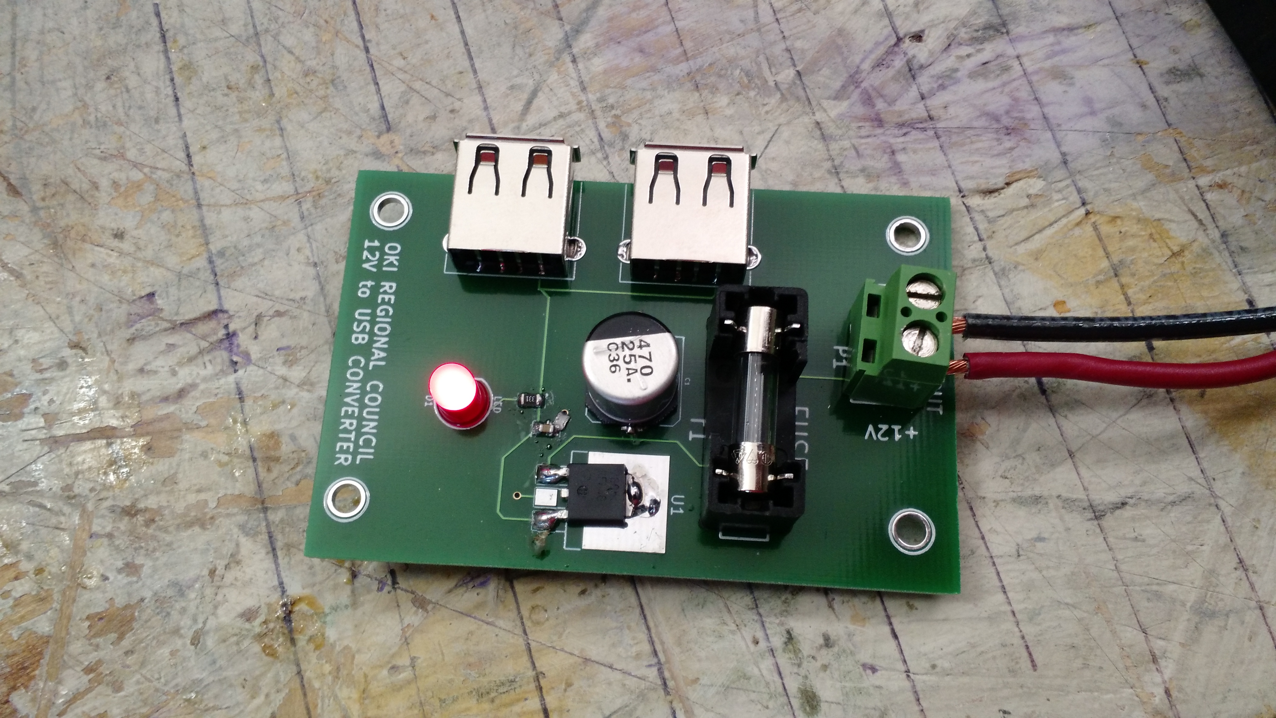
IT LIVES!!! This is one of 5 I built.
I have five blank PCBs left for additional builds should I need it, although I’d have to have work buy more components. Maybe I could get some larger 7805s that would fit the ground pad…
-73-
In terms of success, this ranks up pretty high. I wheeled-and-dealed on everything, and I feel like I made out like a bandit! I didn’t stay very long at Hamvention – I arrived around 8:30 AM and I was gone by around 1:30 PM.
Astron VS-20 Power Supply
It works. I needed a power supply for my bench, and everything new was either adjustable (but not powerful and expensive) or powerful and expensive. This is better than I thought I’d end up with.
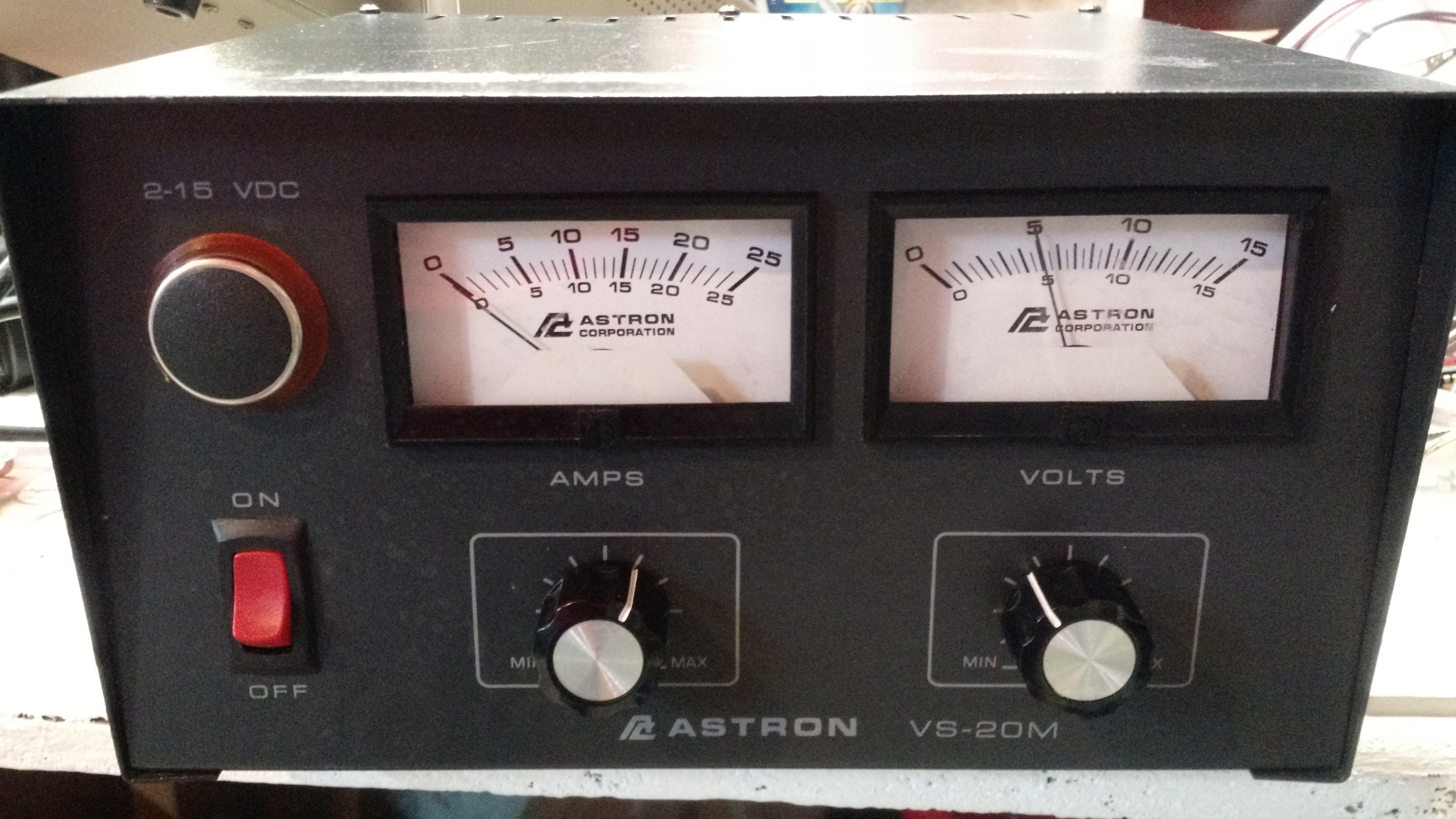
VS-20M Power Supply
RF Millivolt Meter
This is one of those pieces of equipment that I never thought I’d have because they’re fairly specialized. I saw a few, and after finding the power supply, I looked for one I had already found. I found this one (with the probe, not pictured) instead.
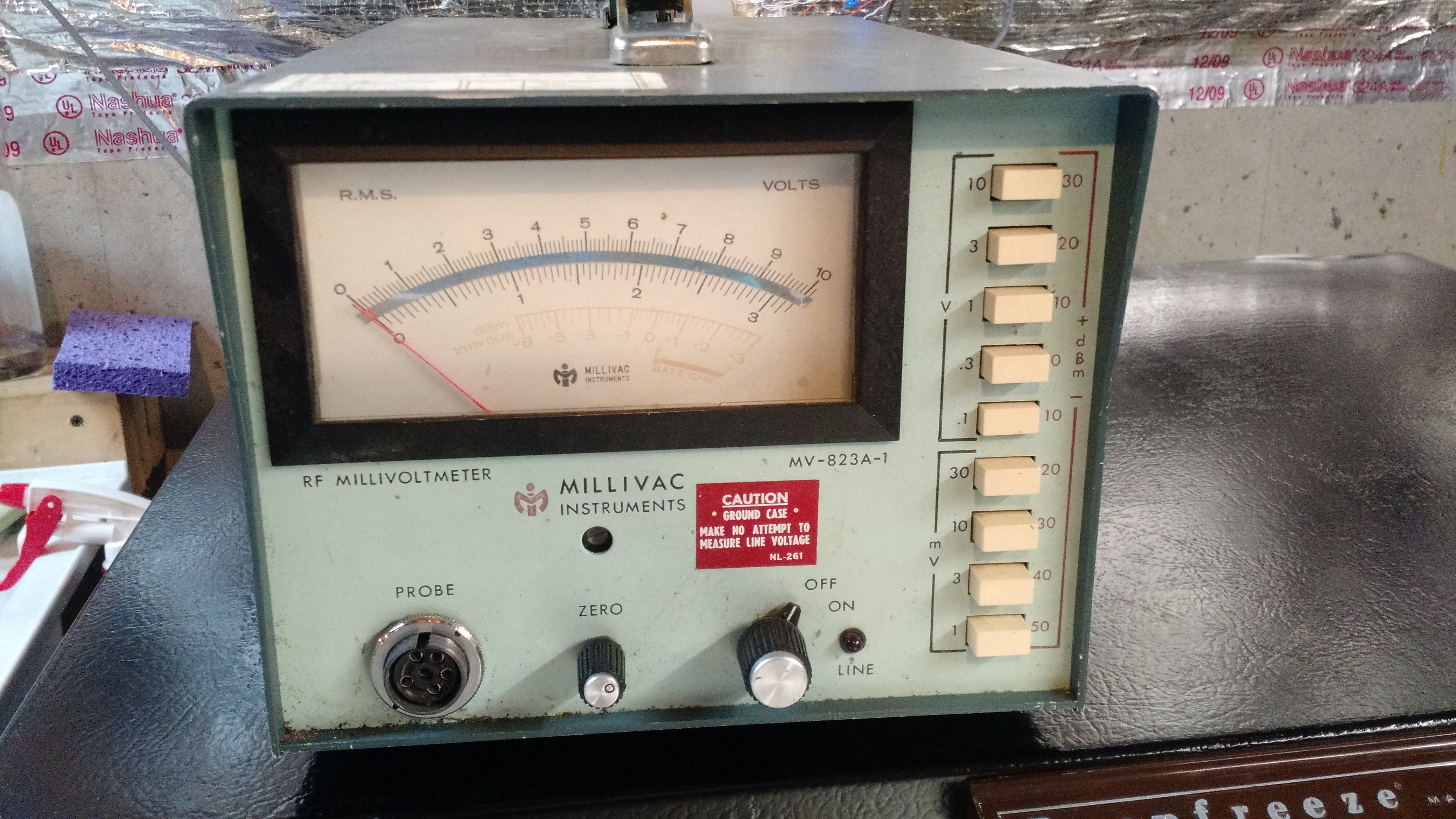
Millivolt Meter
Percent Explosive Meter
I’m surprised someone else didn’t get this first! I couldn’t resist it. This is going to find a place in my basement near a blinking red light. I’m not sure what it will otherwise be connected to (if anything other than a random/semirandom/not-random time controller), though.
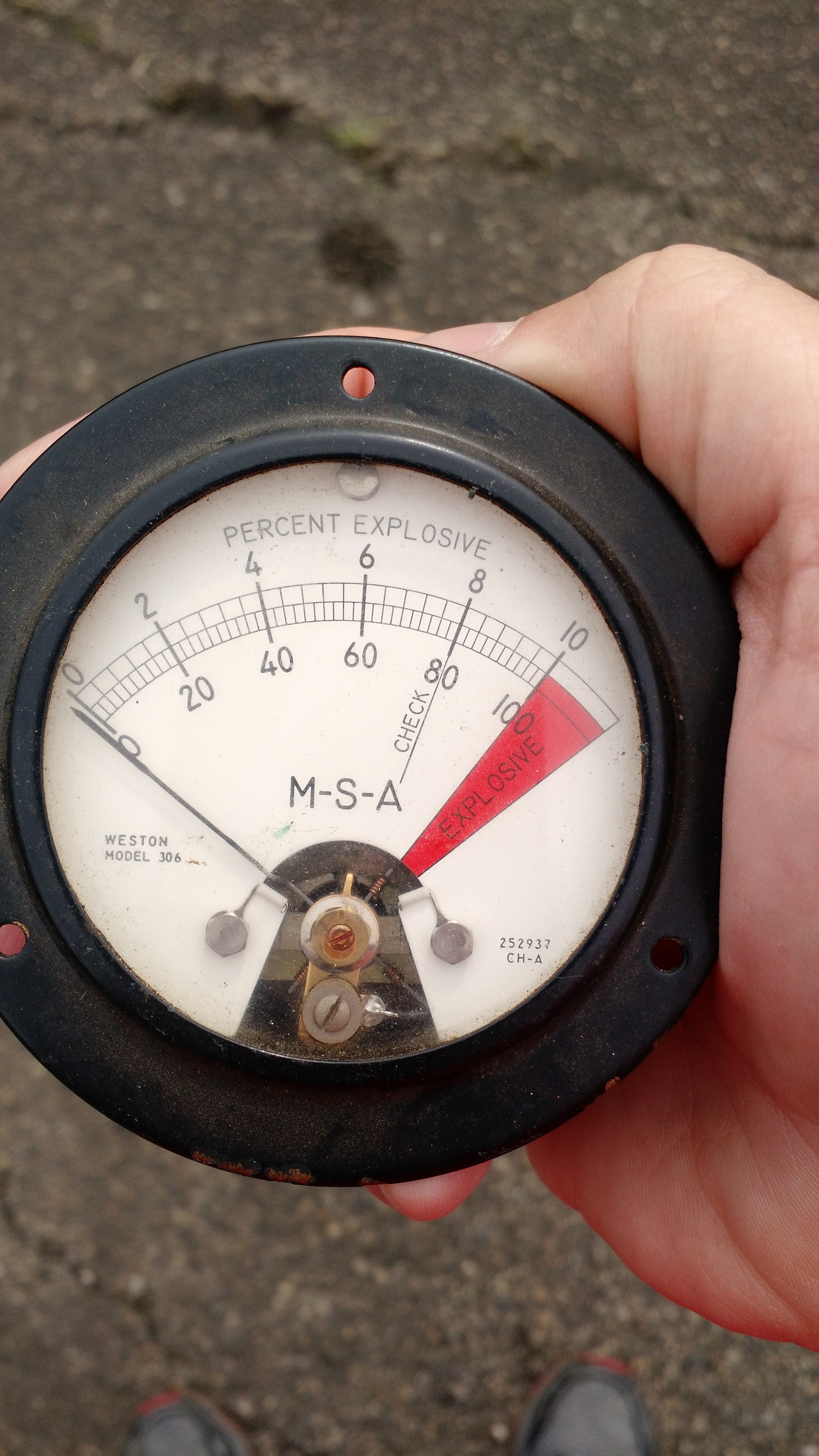
Percent Explosive!!!
Anderson Powerpoles
I’m standardizing on these expensive AF things. I needed some.
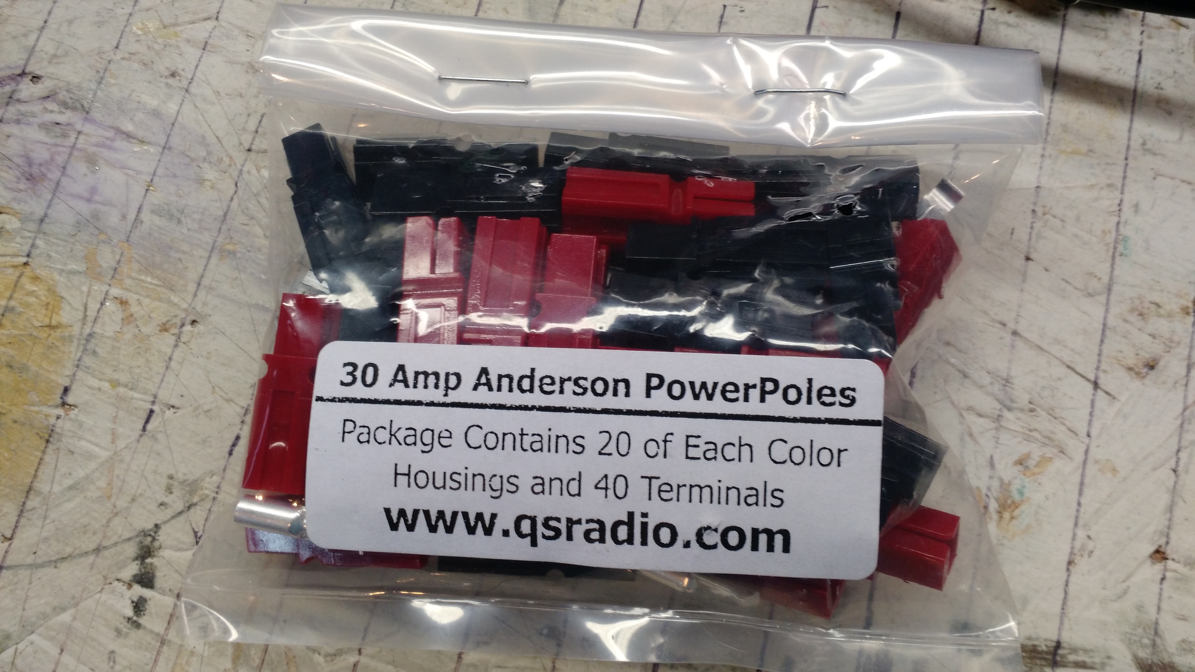
Powerpoles.
Hands On Radio Experiments books
After reading N0AX’s articles in the last few QSTs, the method of teaching has really grown on me. When I saw experiment #161 in the June 2016 QST, which referred back to a common emitter amplifier, I not only read with interest but also decided to attempt the experiment. I started looking for all of the experiments and saw that the ARRL prints them in a book. I found the books at W0TOK books and wheeled-and-dealed to both for $30. DEAL!

Not from Hamvention: Etherkit Si5351 Breakout
I ordered an Si5351 Breakout Board from Jason/Etherkit a few days before Hamvention and got it on Friday after I returned from Hamvention. I got one on the kickstarter campaign, but SEE THE UPDATE BELOW! but for some reason it refuses to work despite some troubleshooting. My guess is that I damaged the chip somehow since I THINK (operative word!) that the two MOSFETs work correctly but my Bus Pirate won’t show an available address . For whatever idiotic reason, each time I get something from Etherkit, I try to hot-air solder it, and it’s all been without the right stuff (either without a proper hot air rework station or solder paste). I’ve been set straight thanks to the Twitterverse, and someday will replace damn near every component on my CRX1 and get it to work properly. And I will always remember the sign in my dad’s auto shop: “Don’t be a fool, use the right tool!”… I’ll also remember Dr. Miller (photography teacher at my high school): “Do not use any equipment for which you have not been trained” (in other words, make sure I know how to set the jumpers before setting power!).
EDIT: I typed all this before testing the new breakout board. The new breakout board was throwing errors, and I found that the new oscillator pulls more current than the Bus Pirate seems to want to provide. After finding this, nothing could be found with the I2C search. I looked back on this blog and found “the CLK pin on the Bus Pirate gets connected to the SCL pin on the demo board and the MOSI pin on the Bus Pirate gets connected to the SDA pin on the demo board.” I now have two functioning breakout boards! 🙂
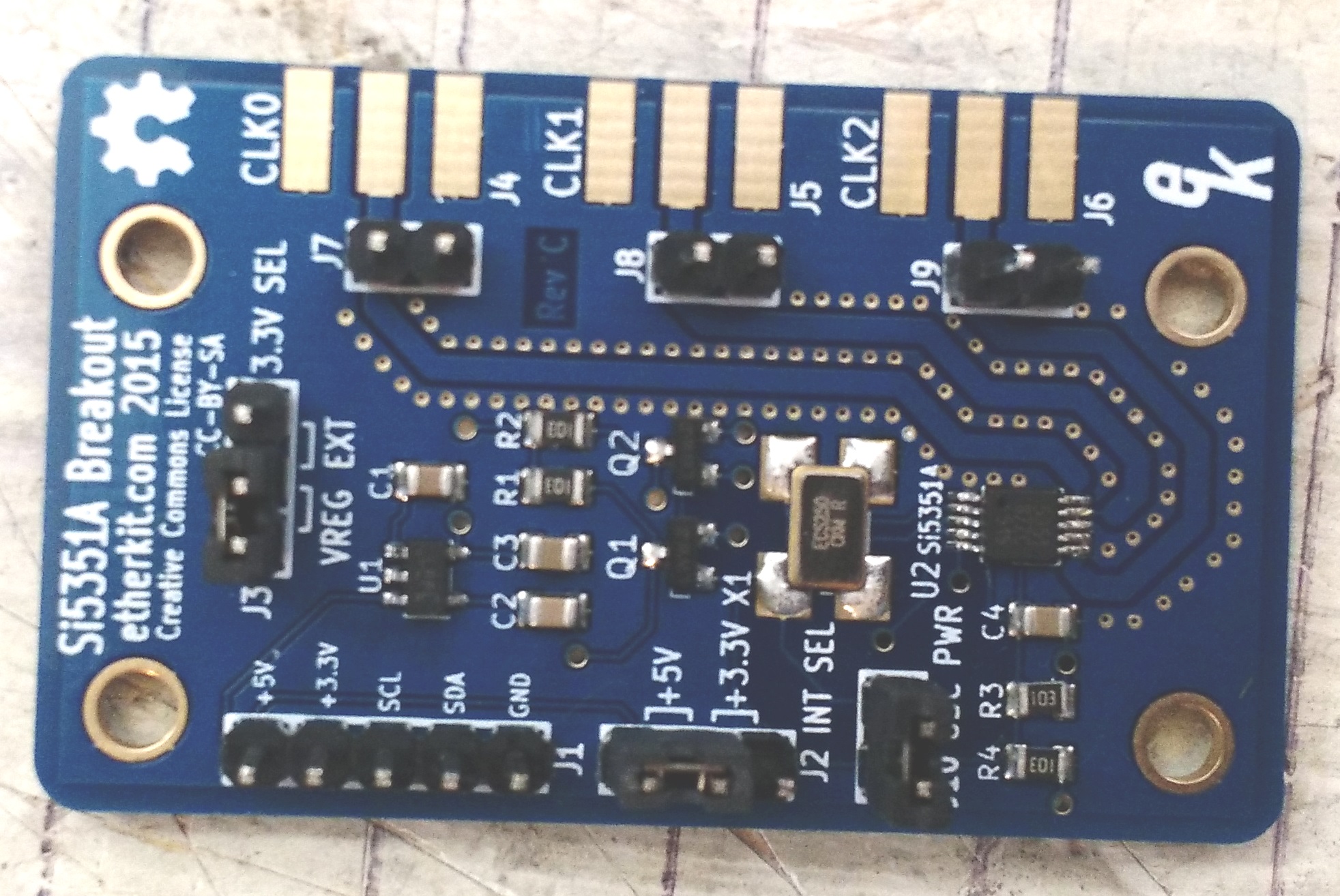
Etherkit Si5351 Breakout
That’s it! 73!

Maybe it’ll be a good day! From WHIO TV 5/16/16
I’m going to Hamvention on Friday. My shopping list consists of a handful of needs:
- A power supply (preferably a linear supply capable of >=20 amps continuous, but I’d go down to 10 amps switching if needbe)
- Powerpoles
- An NMO mount or two
- Variable resistors: 500 ohm, 50k, probably a few in between
- Something to make a 100Mhz or 125Mhz oscillator
- Probably a few other parts
- Some MOSFETS… particularly an MPF-102 for this
I’ll probably come home with other stuff too…
-73-
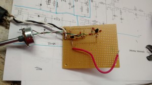
I decided to build a Colpitts oscillator after watching one of W2AEW’s videos.
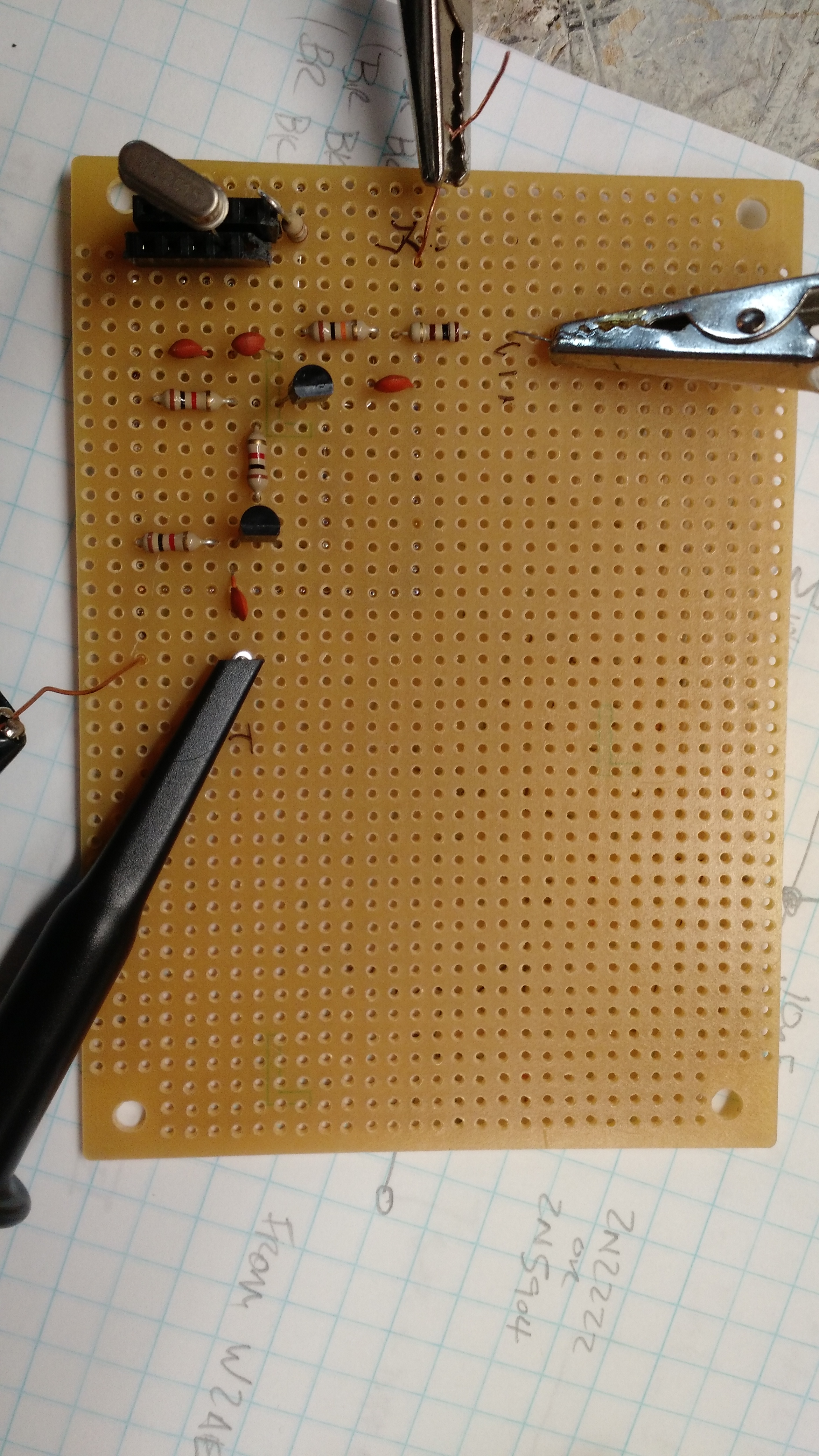
Circuit Board
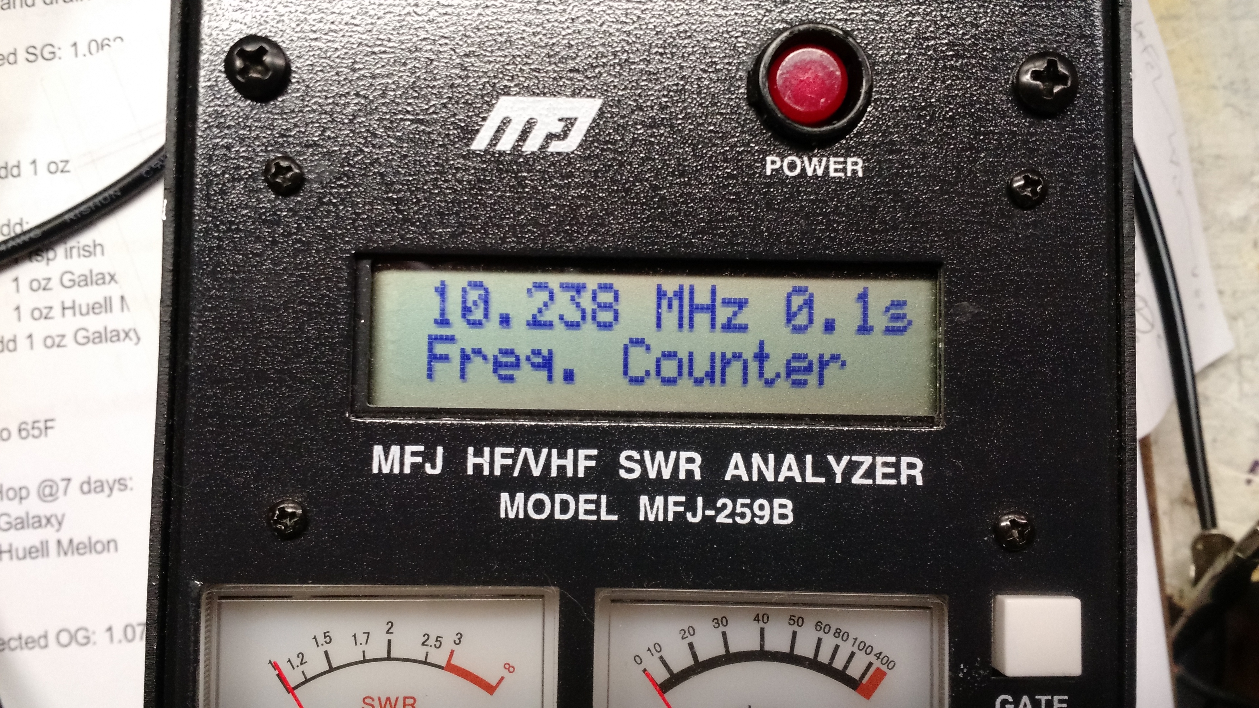
Frequency Counter
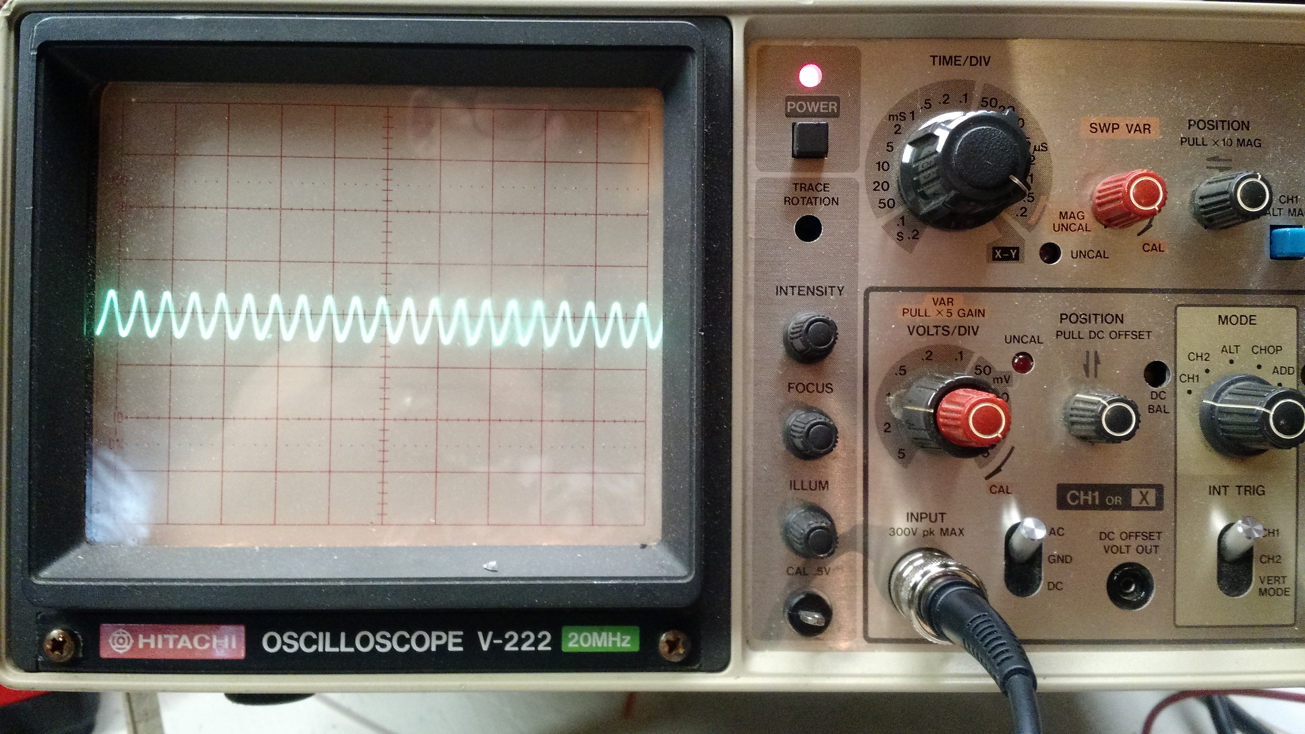
Waveform on the scope
The only issue I ran into was that I had the power supply hooked up backwards, so when I initially connected it to the scope, the +12V shorted to ground (and it burned a small hookup wire in the process). I should have paid more attention to the testing that W2AEW describes in his video – on a second try, I was seeing -7V where I should have been seeing +5V. And I shouldn’t have trusted the two hookup wires I was using to get from a computer power supply output to a circuit.
I also didn’t have 2N2222 or 2N5904 transistors, I used 2N3904s, which seem to work fine.
-73-
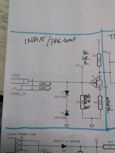
This is the second part of something that has been sitting on my workbench. Part I.
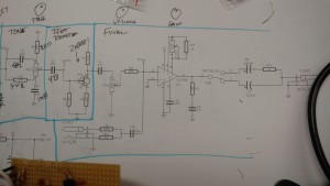
The schematic…
The video below shows the two traces of the input and the output of the second JFET.
The board is coming together as much as it could be for not being printed or having an enclosure.
Through the tone control
The third part will be waiting for me to order a few pots, which I forgot to put on my last parts order.
-73-
With all the issues surrounding FTDI chips and drivers, I decided I’d look at a competing chip – the Microchip MCP2221. Unlike the “standard” FTDI FT232 (which is most similar to the MCP2200), the MCP2221 includes both a UART and an I2C interface.
Hookup and Configuration
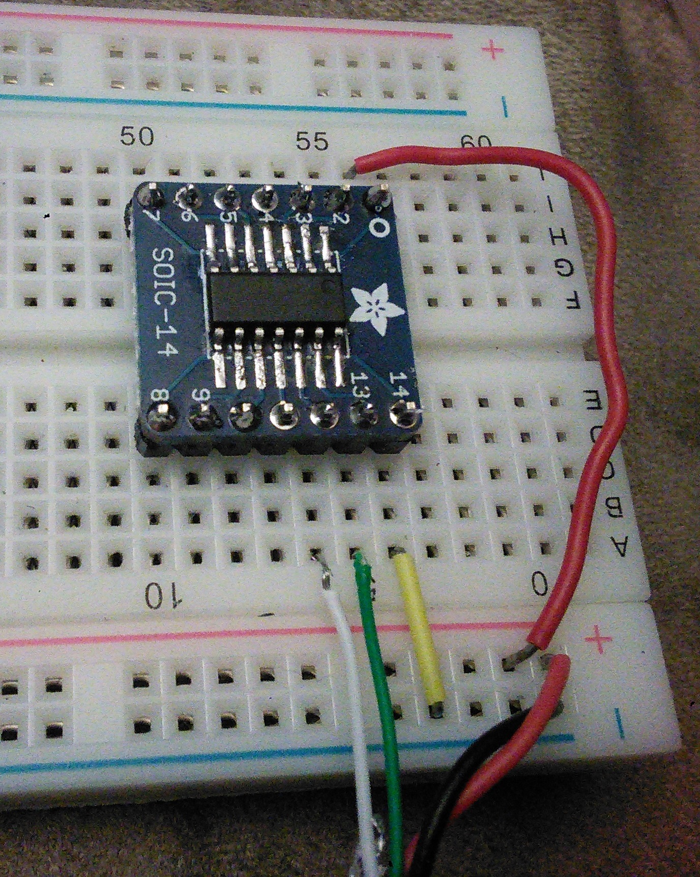
Hookup
Hooking up this is pretty easy. I sacrificed a USB cable and pulled the red to Vcc on pin 1, black to ground on pin 14, white to Data- on pin 12, and green to Data+ on pin 13.
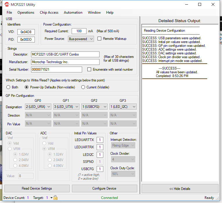
After that, I checked things using the Microchip MCP2221 Utility from Microchip. One of the more interesting things in the utility was being able to configure four pins:
GP0 (pin 2), default is UART RX LED, but can also be SSPND (suspend?) or GPIO
GP1 (pin 3), default is UART TX LED, but can also be CLK_OUT (clock out?), ADC1, IOC, or GPIO
GP2 (pin7), default is USBCFG, but can also be ADC2, DAC1, or GPIO
GP3 (pin 8), default is I2C LED, but can also be ADC3, DAC2, or GPIO
I2C Connection
The real reason I got this was to be able to interface to both I2C devices and UART (serial) devices, so I hooked a TC74 temperature sensor to it.
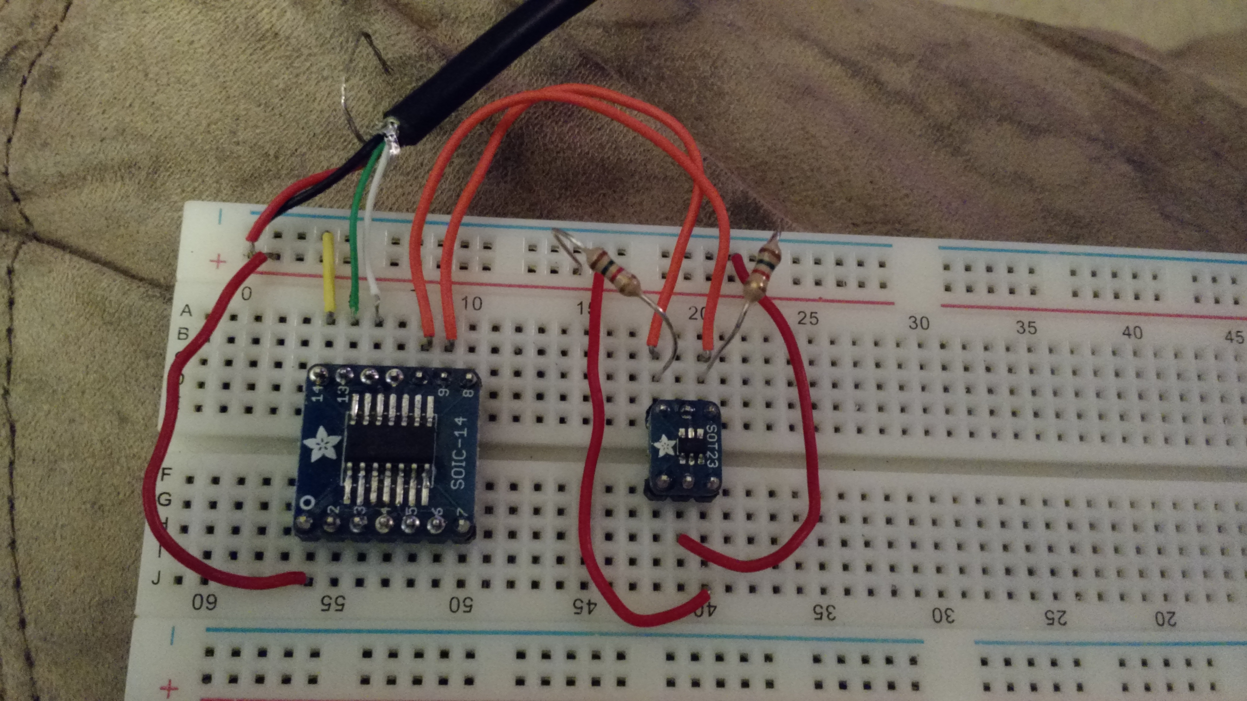
TC74 hooked up to the MCP2221
The hookup is straightforward, the TC74 uses four of it’s five pins, Vcc, ground, SCL, and SDA. Vcc and ground are pretty self explanatory, SCL and SDA go to pins 10 and 9 on the MCP2221 (respectively). The SCL and SDA lines need pull-ups, I used 1.5k resistors.
To check things, Microchip provides an I2C/SMBus Terminal program.
Under “Advanced settings” you can scan the bus by giving it a range to scan…
Scan the entire bus
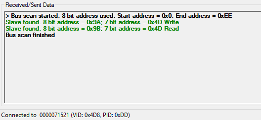
Scan results. Found the TC74 right where I expected it.
Once I verified that the sensor was where I thought it was, I used the terminal tool to read it…
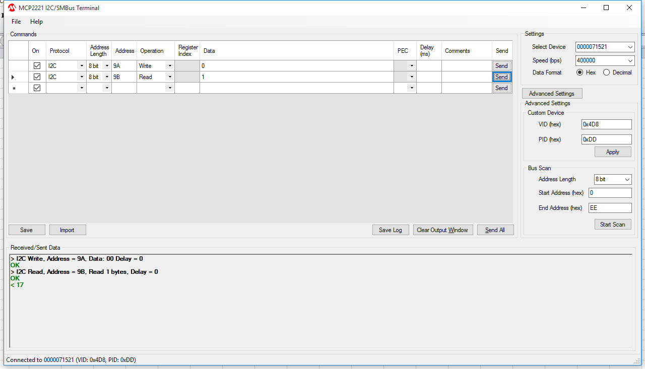
0x17… 23C… 74F…
So the next steps are to figure out what I want to do with all this… I’m partly thinking a multi-function breakout board – UART, ADC and DAC
-73-
Some time ago I built an Internet gateway (iGate) for monitoring APRS packets and sending them to APRS-IS. It never made it to the blog partly because it was built out of Direwolf, so it was mostly software configuration.
Since then, I’ve had trouble keeping soundcards running in the same configuration and the iGate was offline for some time.
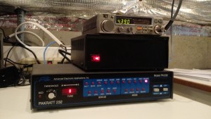
Last summer (or the one before it, I don’t remember), I bought the components to a packet station: an AEA PK-232 TNC, a Kenwood Mobile, and a broken power supply. The broken power supply is still broken, but the rest is up and running.
The APRS Receiver Setup
The setup for the PK-232 is courtesy of LA6YIA on Google Groups:
XFLOW OFF
AWLEN 8
PARITY 0
RESTART
CONMODE TRANS
TRACE OFF
HID OFF
BEACON EVERY 0
PACKET
RAWHDLC ON
HPOLL OFF
PPERSIST ON
KISS ON
HOST ON
The APRX setup is not groundbreaking, but it’s below, too, since it may help someone…
Then, since the ultimate test is to make it work, I wrote a simple Arduino Sketch using the Argent Data APRS Arduino shield and my trusty IC-T90A…
Obviously, this only transmits once, and it is using manually-entered location, but it does the job.
Look! It’s here!
And of course, I could find some repeats in the log:

I’m in the log!
So at this point there should be better coverage in the far east of Cincinnati.
73!
Backstory
Many months ago, my brother-in-law brought over a guitar with the thought of “you fix it, I’ll cover the costs, and we’ll split the profits”. It wasn’t a bad deal, so I started fixing it. A month later, after I preceded to remove a large part of the partially-damaged finish, he called and told me that he got another guitar and he was no longer interested in pursuing it.
So it sat for many weeks.
And it sat for a few more weeks.
Finally, the same brother-in-law brought over a Marshall head that blew a fuse and a few diodes to repair. I needed a guitar to test it with, so I finished stripping it and ended up with something that looked decent and actually played (which I ultimately used to test the amp).
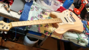
Guitar
Around the same time, Hack-A-Day posted about the 1Wamp, a small, battery powered amp. The schematic looked like an easy build, and I was fairly certain I had all the parts lying around.
Amp Build Part 1: The Preamp
The preamp is very simple: 3 resistors and a JFET.
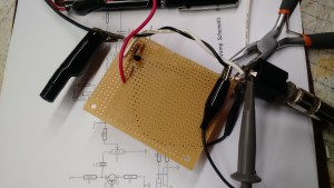
Yeah, pretty simple.
Simple Schematic (well, this part is, anyway)
I skipped the Zener diodes, which are there for static protection. I’ll probably add them in at some point in the near future.
It does work. I hooked it up to a 12V linear power supply and took a video of the input (from the guitar) trace and the output trace from the preamp.
The input is about 0.6 – 0.8 Vp-p. The output is about 1.6 – 2.0 Vp-p. That puts it somewhere in the range of 6-8 dBV. That’s a little over spec, but I’m also feeding it 13.8V instead of 9.0 – 9.5V.
Next up: the Tone Control. zOMG 6 components!
73!
I recently had the need to check a transceiver to ensure that it was on-frequency. This is easiest done with a frequency counter, which is included in an MFJ Antenna Analyzer. I use an inductive coupler made from some coil wire around a small (1/2 inch) piece of CPVC, with the coil connected to a BNC connector.
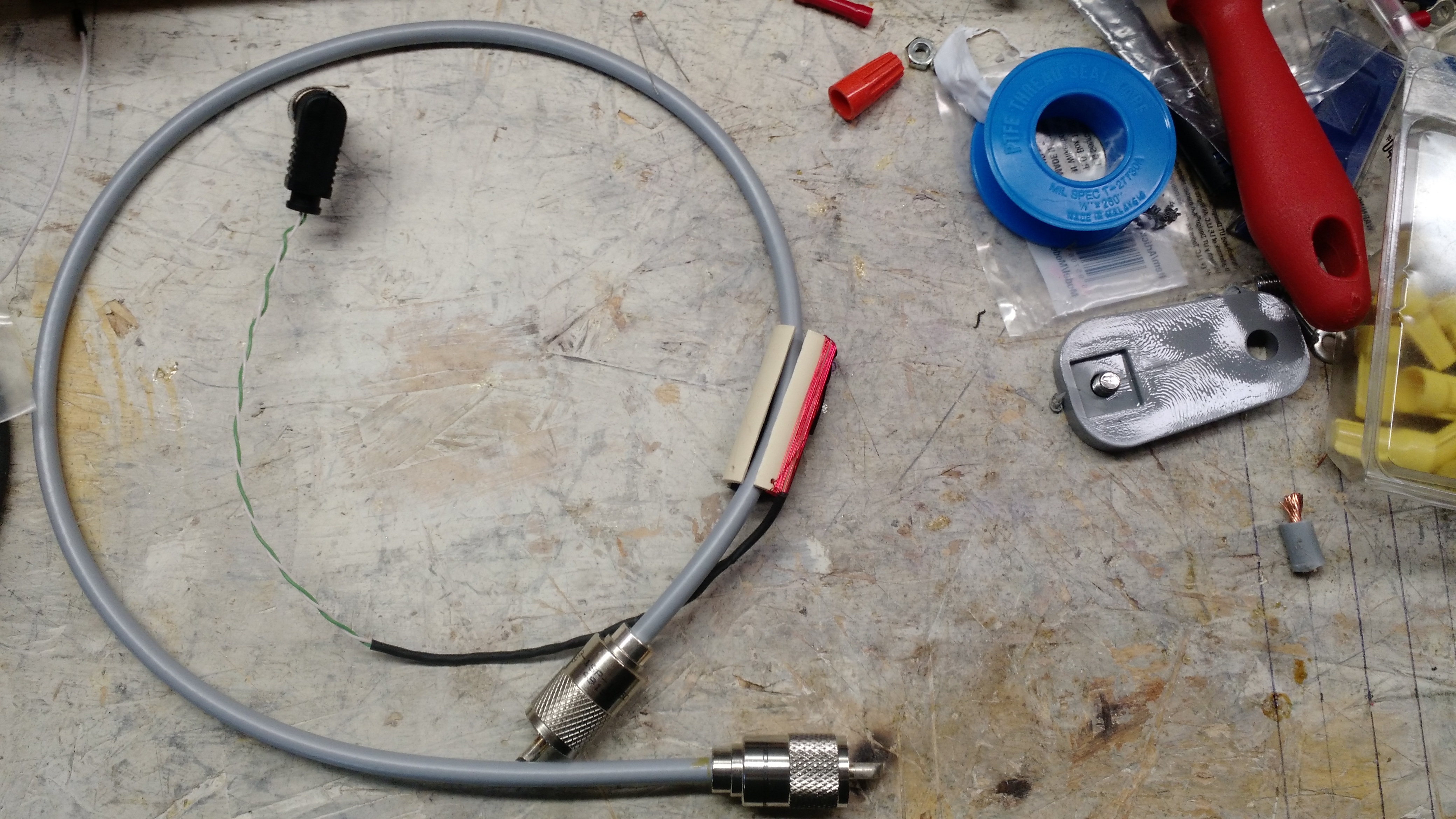
Inductive Coupler
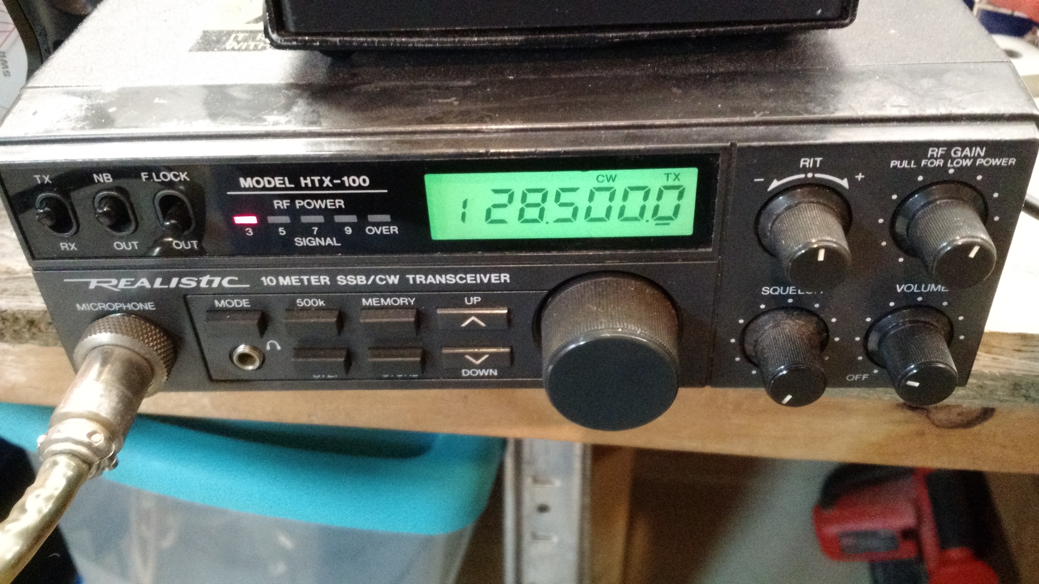
Radio set frequency (28.5 MHz)
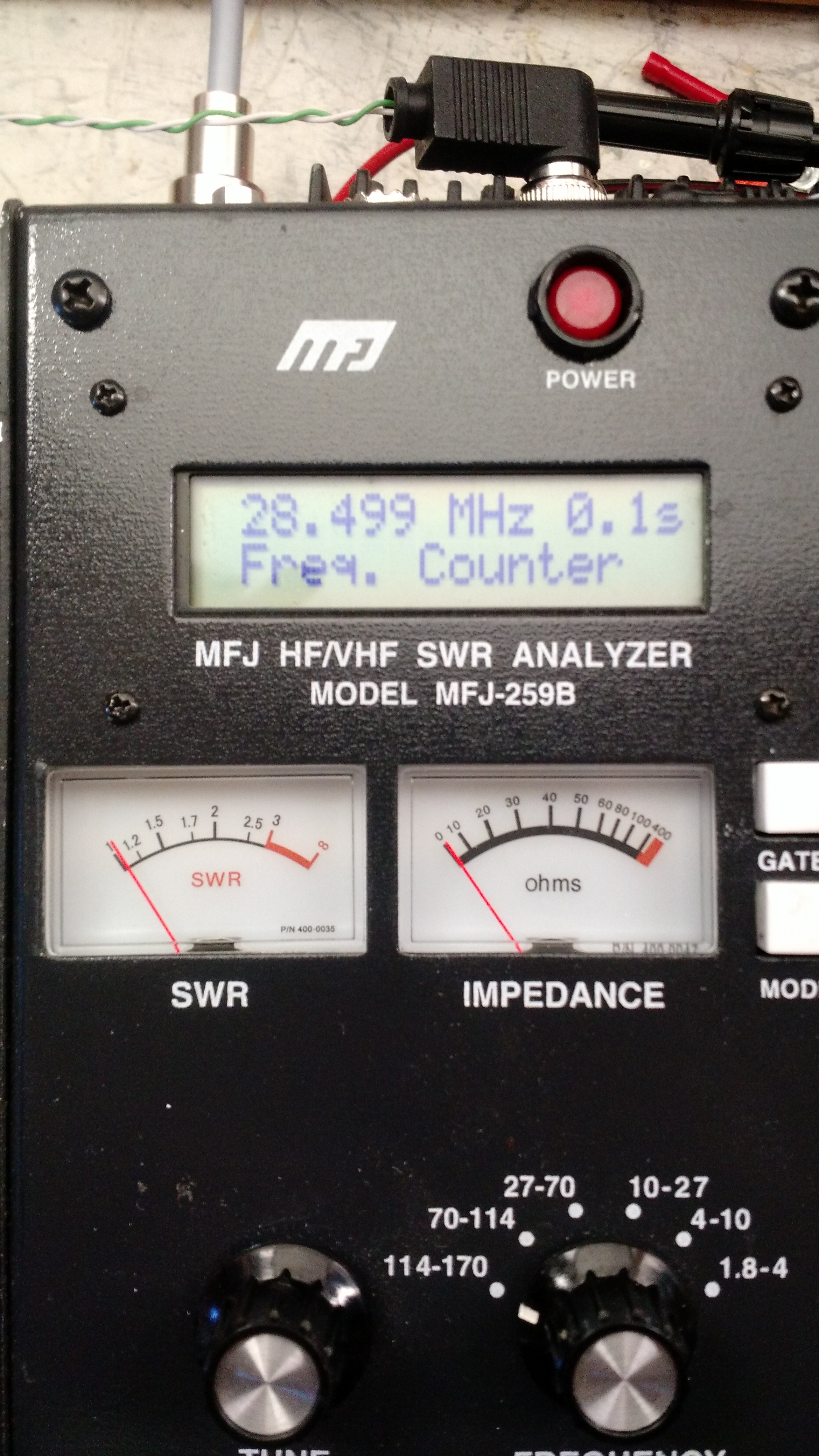
Frequncy (28.499 MHz, or close enough considering the potential error in the antenna analyzer)
-73-
Hamvention is at a busy time for me, and I didn’t know if I was going to attempt to go or not. I think I’m going to go, though, because I need stuff.
- New NMO mobile antenna setup
My current mobile antenna is a few years old and not only is it showing it’s age – the coax is pulling out from the magnet and I can see braid – it probably took damage when I wrecked my truck last October. The truck is repaired, but the antenna currently has a VSWR of 3:1. Not good. I’m going to completely replace the antenna setup with a better one. - Parts
I’m not looking for any real radio equipment other than parts. I have some specific needs (linear-taper variable resistors, etc), but nothing out of the ordinary. - Arduino/Raspberry Pi/Beaglebone Black stuff
Because you can’t have too much! - Test Equipment
Generally, another scope or a spectrum analyzer is out of my price range, but if I happen to find one…
So I’ll probably be at any Reddit or WATwitter meetups, and I’d assume the same location as last year.