
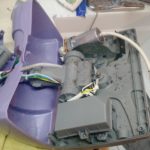
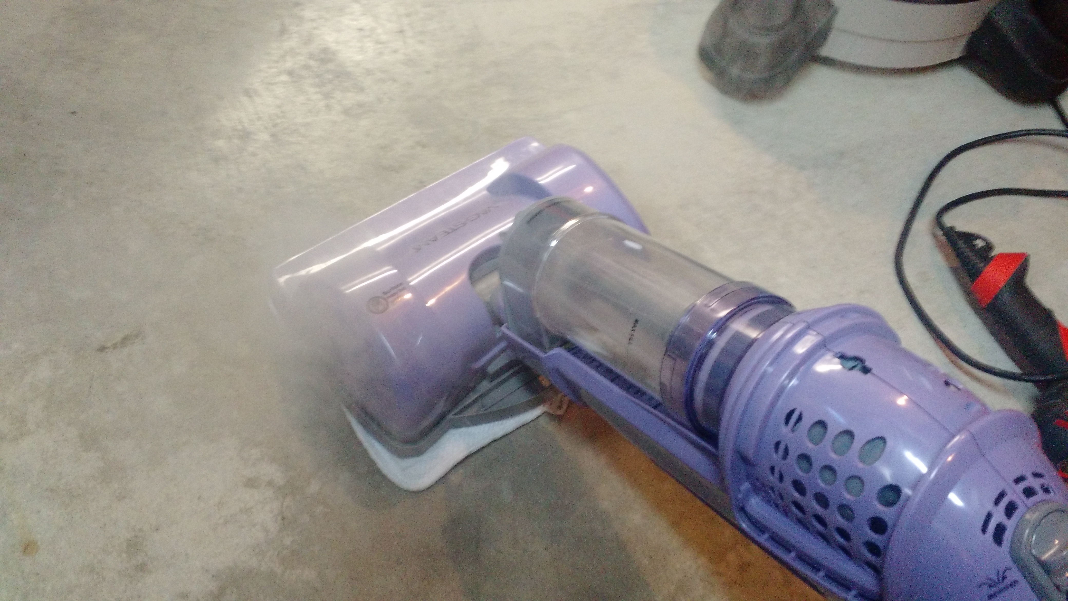
WifE8P was complaining that her Shark Steam mop was not producing a lot of steam. That’s really the only way we clean the dining room, kitchen, and entry floors, so it’s pretty important for it to work.
The steam would act like it was operating, but would put out little steam.
-
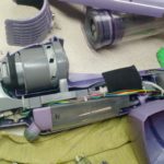
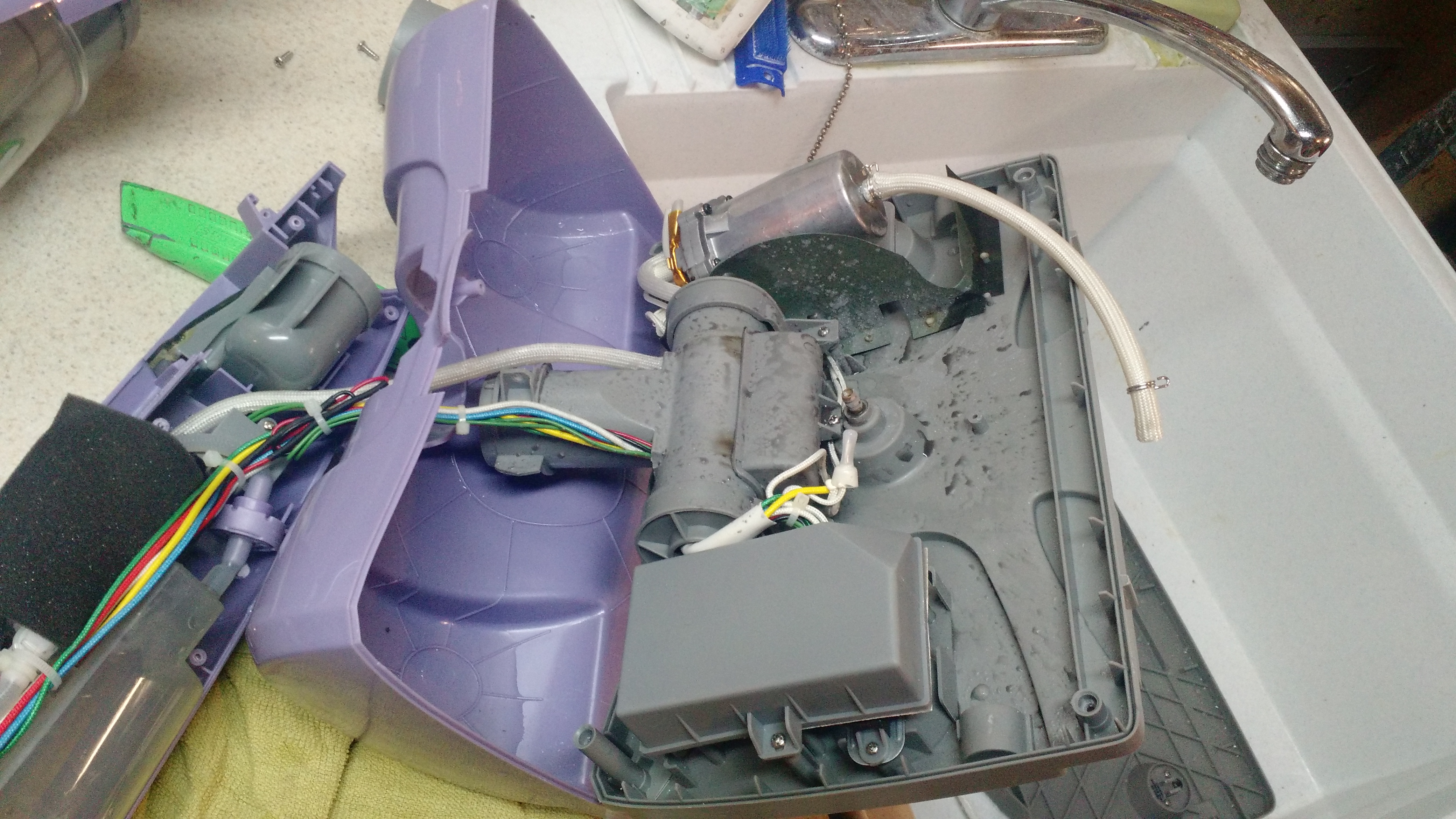
- This is actually pretty easy to take apart. The only tool required is a Philips screwdriver, and there are few clips.
-
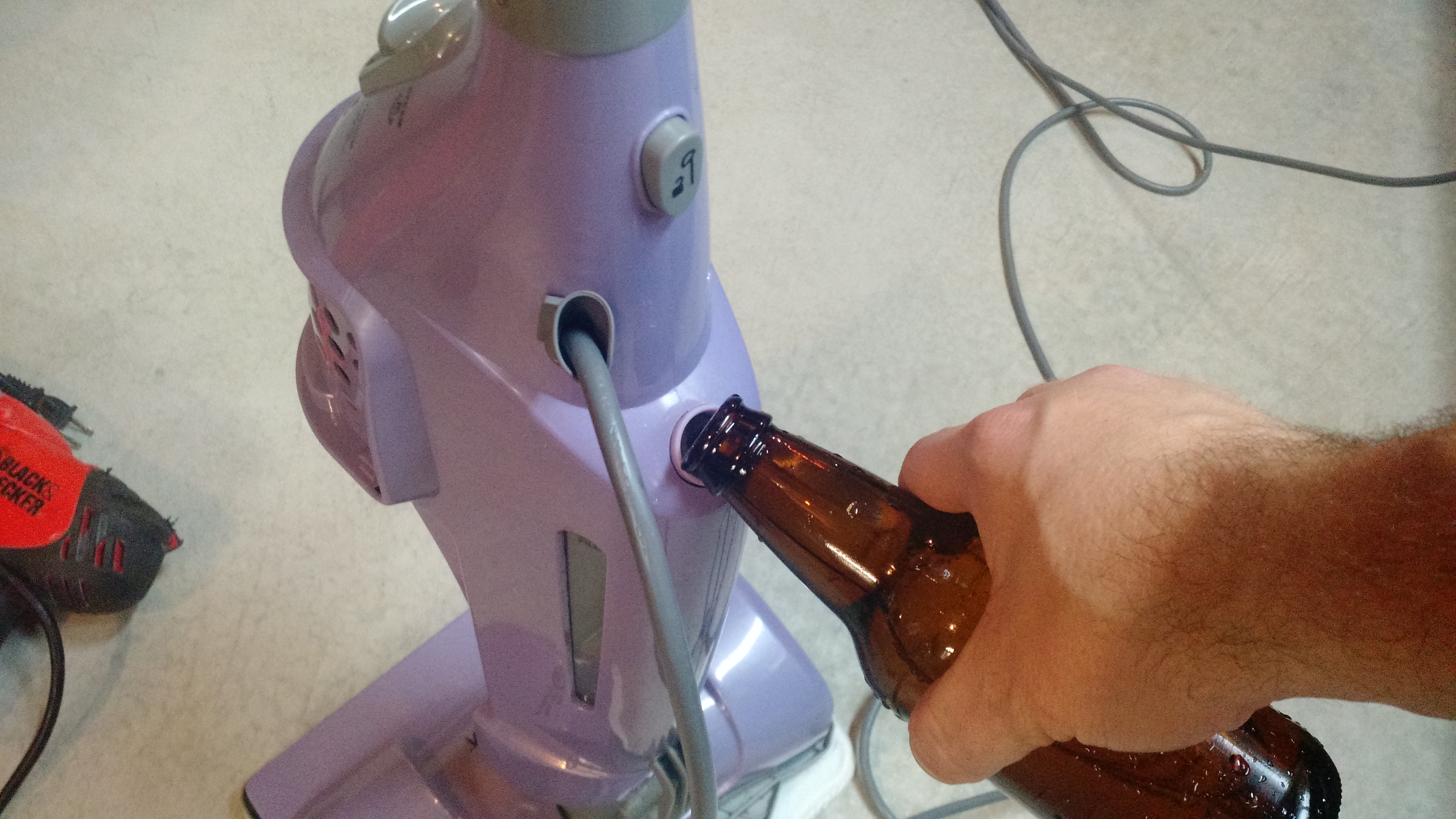
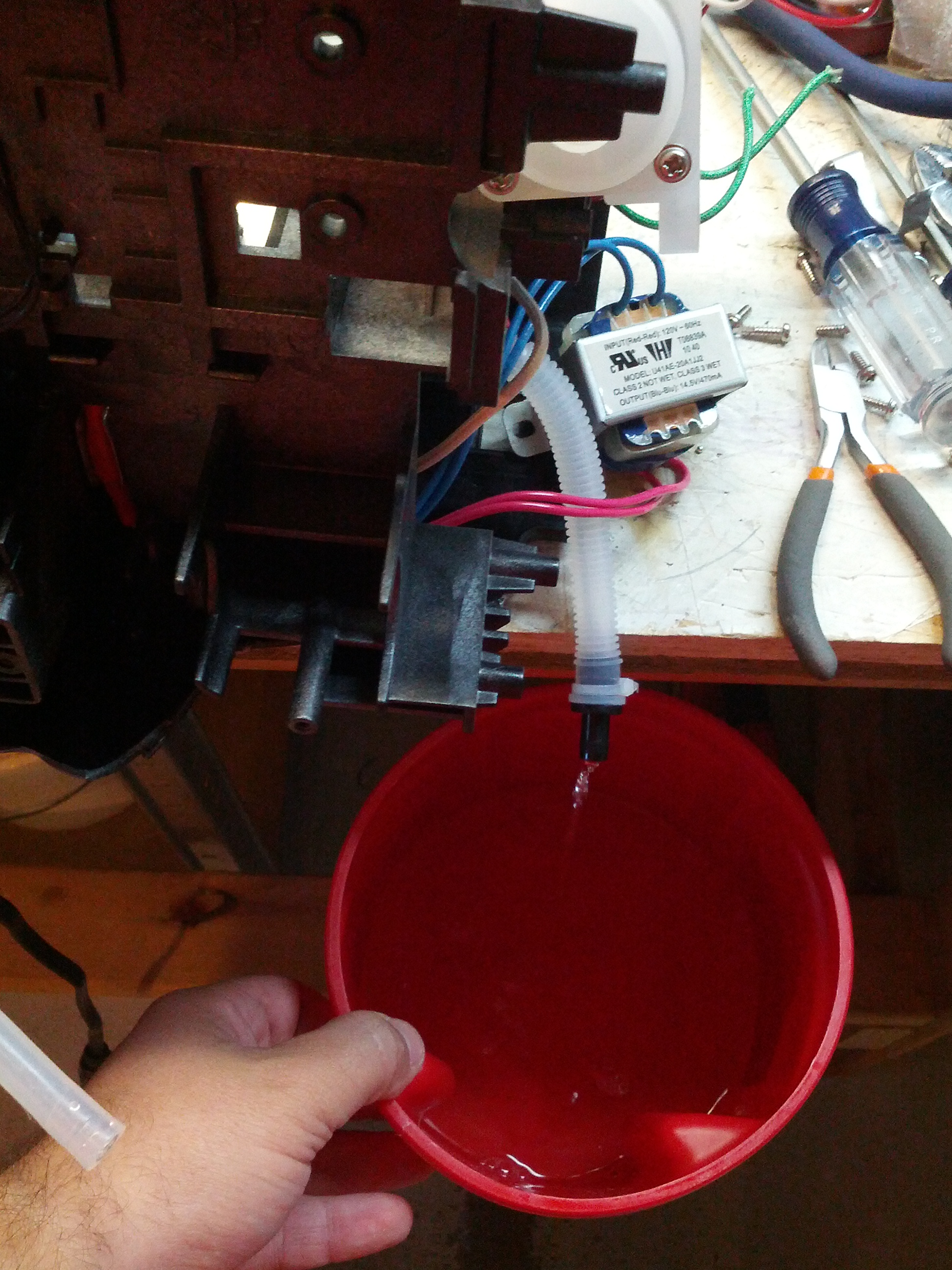
- This is the pump. During troubleshooting, the pump DID (and still does) work. The fact that it was operating and nothing was coming out means that it was pressurizing the hose going from the pump to the mop head nozzle.
-
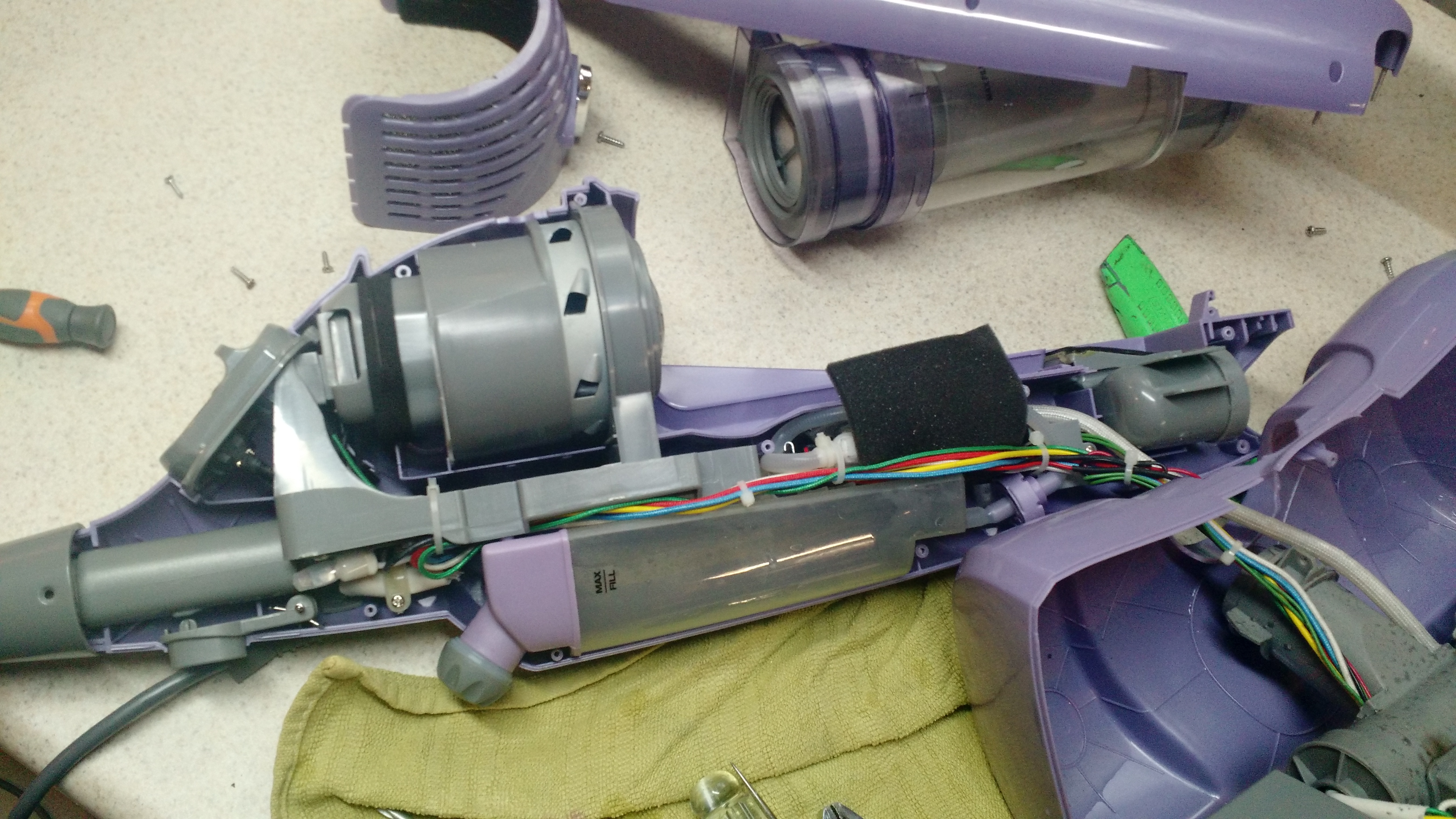
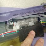
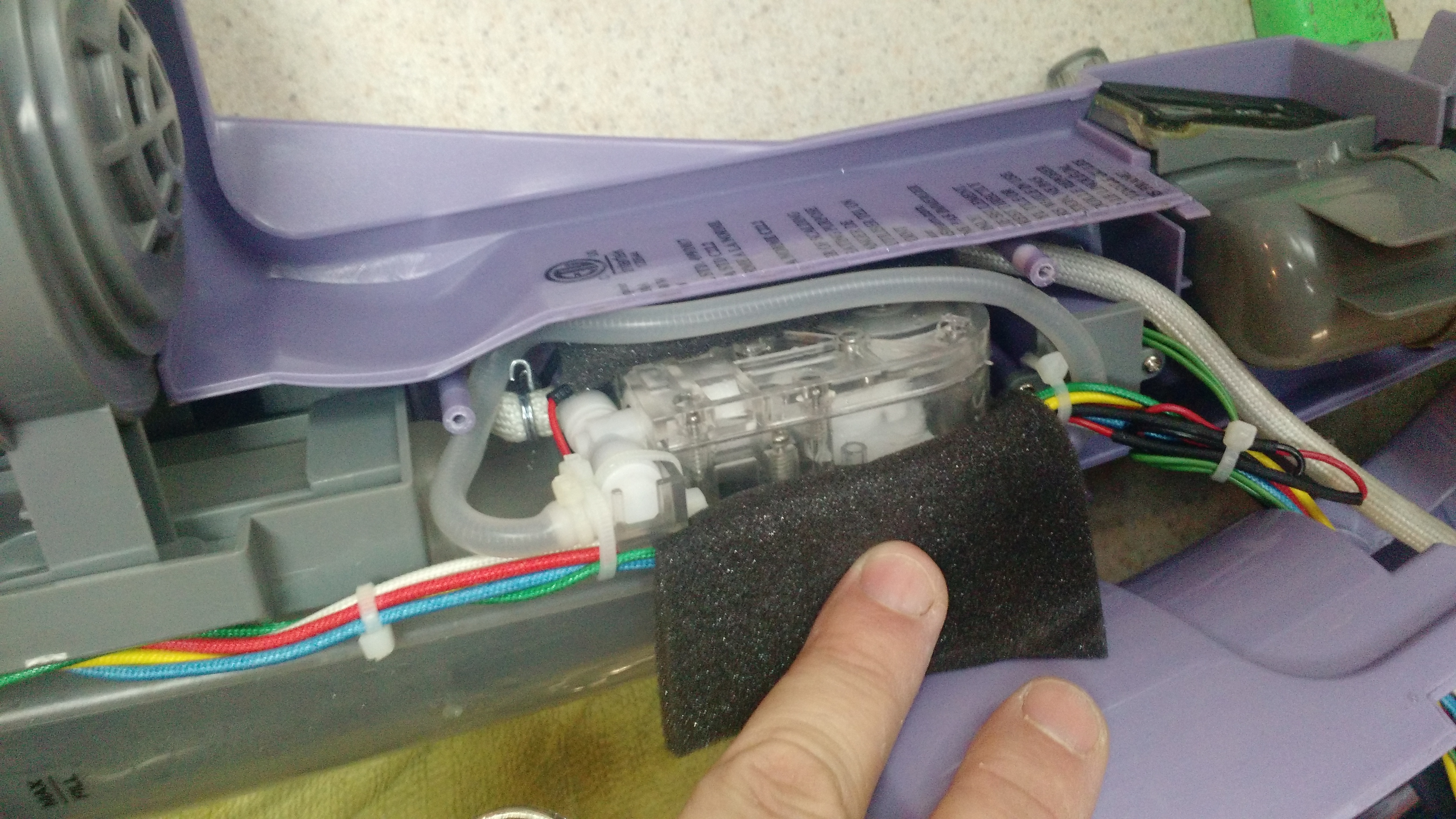
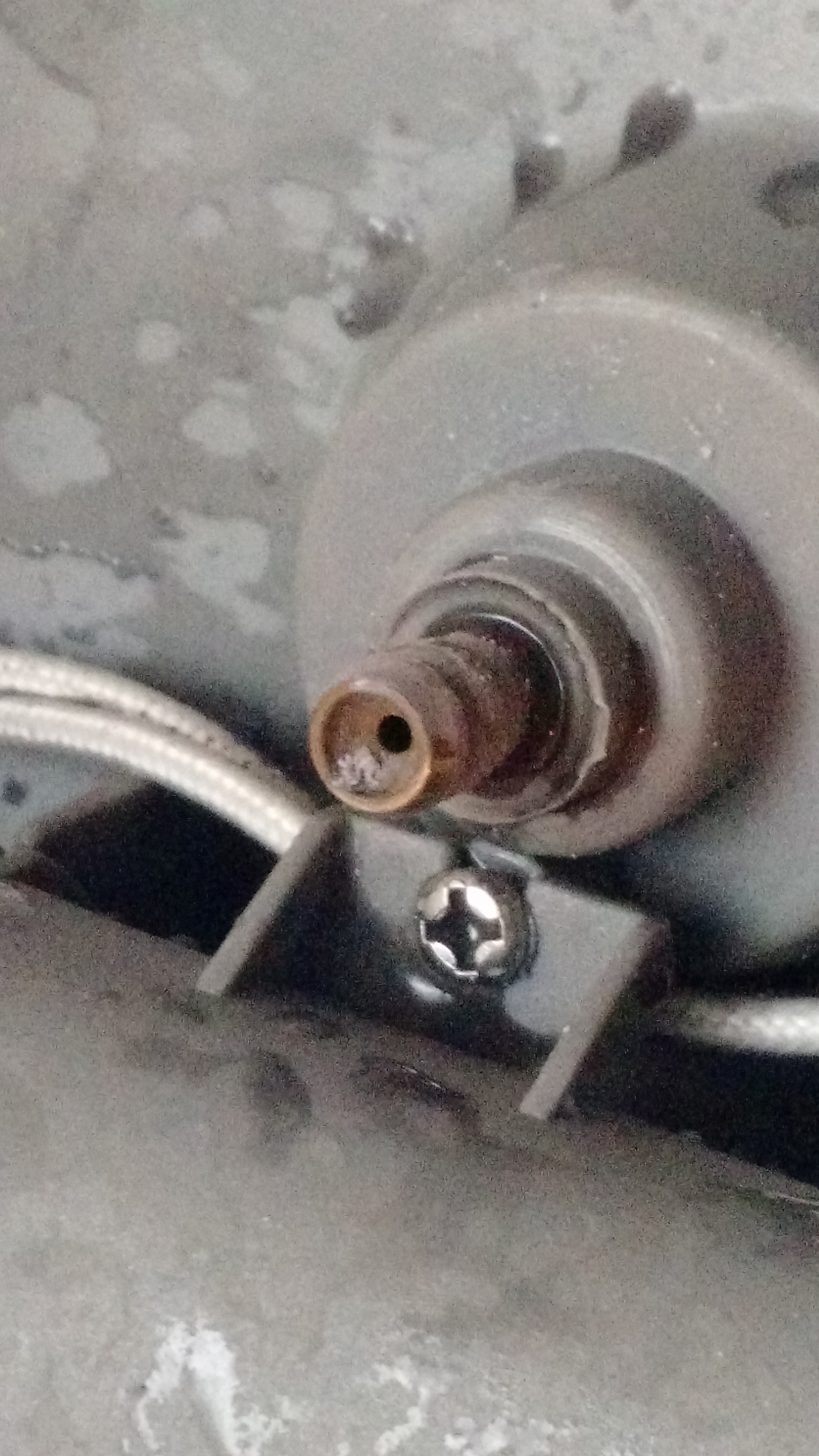
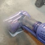
- This is the inside of the sweeper/mop end after removing the steam hose from the outlet. DANGER: STEAM. HOT. I was lucky it fired AWAY from me!
-
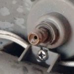
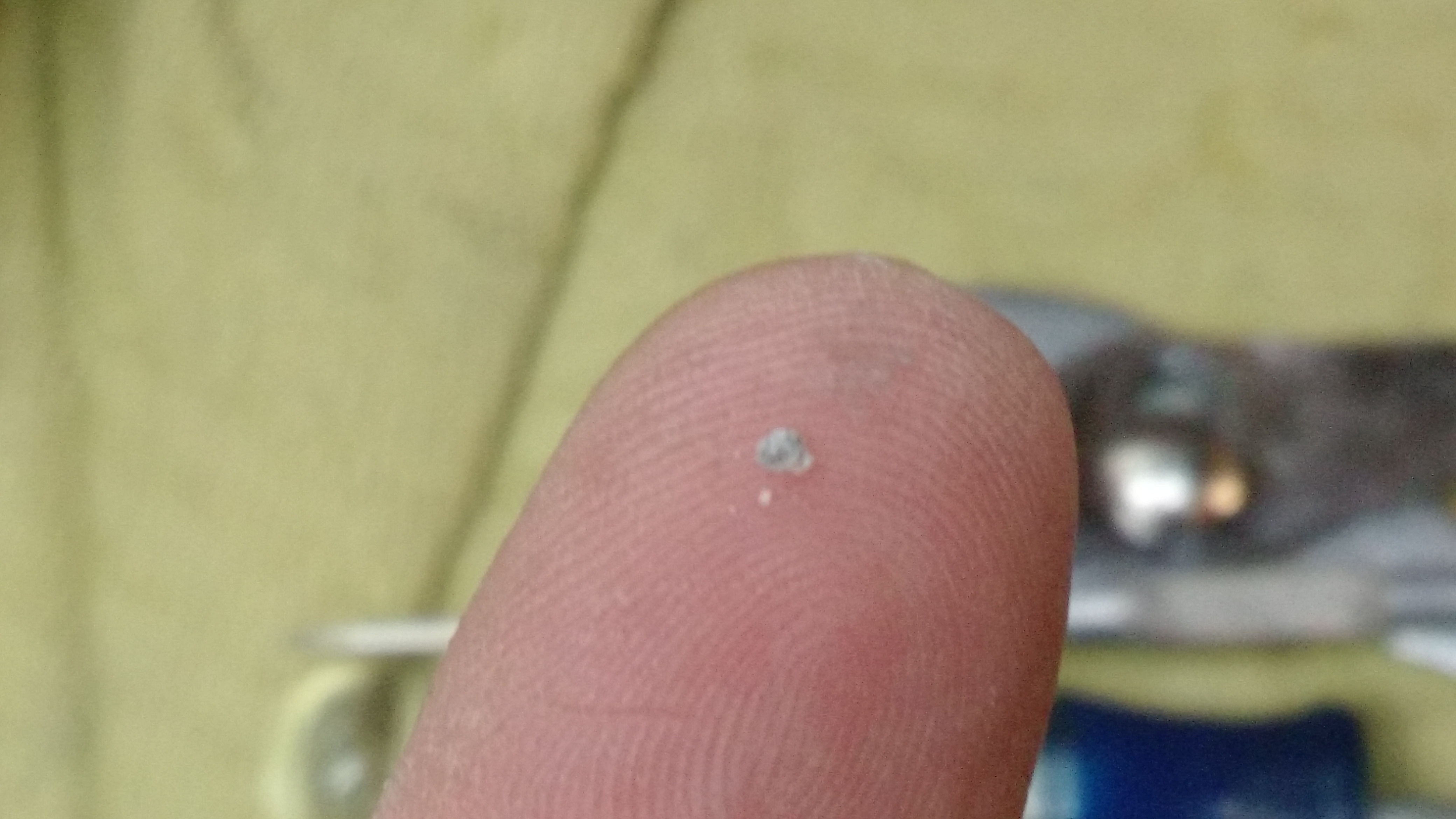
- This was the problem – a pebble made it up to the outlet nozzle.
-
- This is the pebble.
-

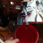
- Filling to test.
-
- It works!
-73-
I happened to stumble on an advertisement for a cool looking device that would work with a phone via Bluetooth. It was ideally something that would be used for things like movie times, bus waiting times, or something else small and URL based… kinda like a QR code without the annoying camera part.
So I got a pair of RFduinos to play with it. Programming it is quite simple, you just need Arduino 1.5 or later (which you would need for programming a Yun, Due, and possibly a few other Arduinos) and the RFduino libraries (see this). The library comes with an example program accessible under File-Examples-RFduinoBLE-AdvertisementContinuous.
The only somewhat difficult part is dealing with the URIBeacon, and Adafruit publishes a tool to help with that, and Google has a more detailed explanation.
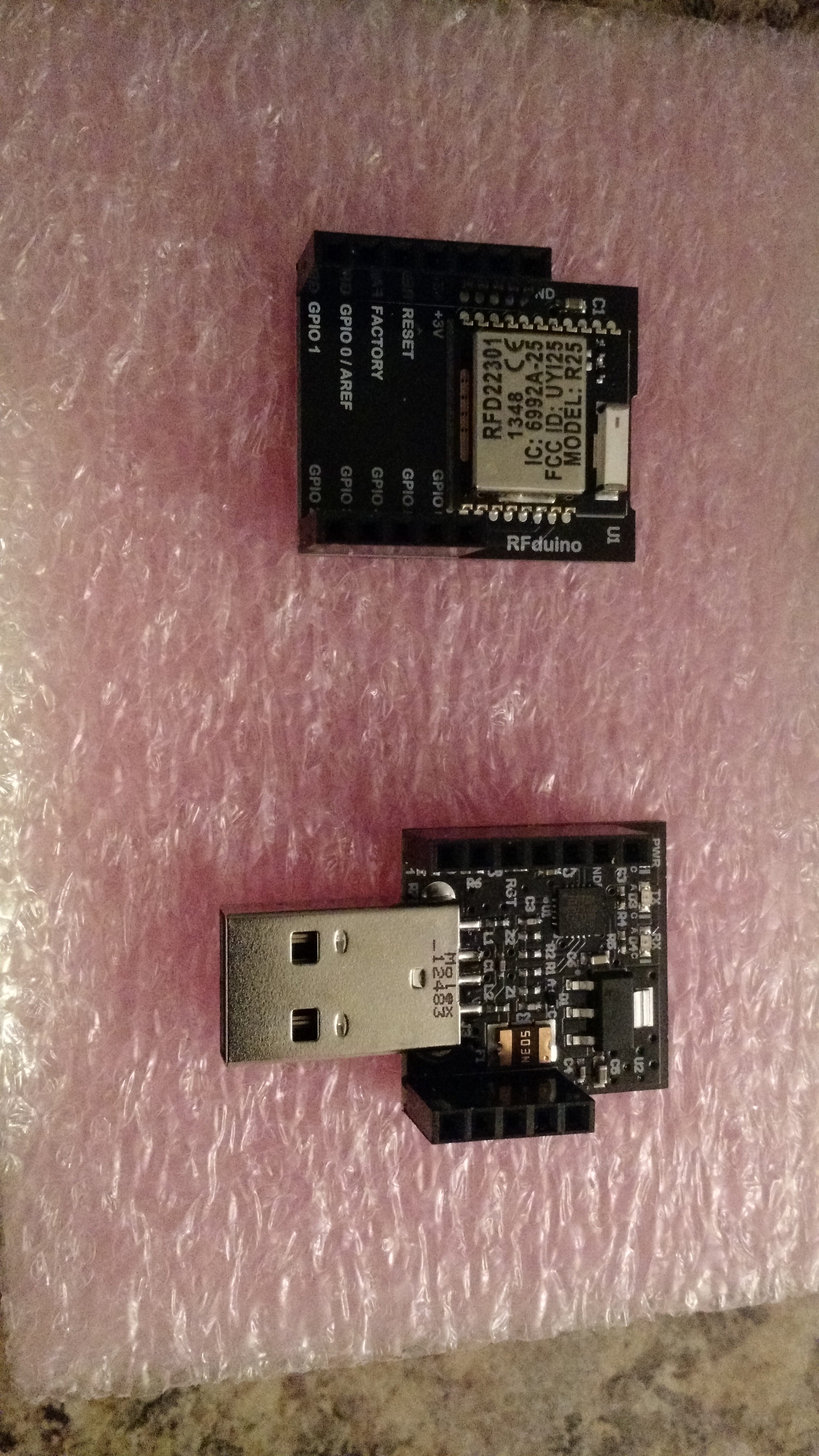
The top is the RFduino, the bottom is the USB shield, which is the easiest way to load it.
Of course it does nothing unless you have a device setup to receive it. In the Play Store, there is a Physical Web app that can be used to receive the messages (until these become part of Android… and hopefully iOS, too).
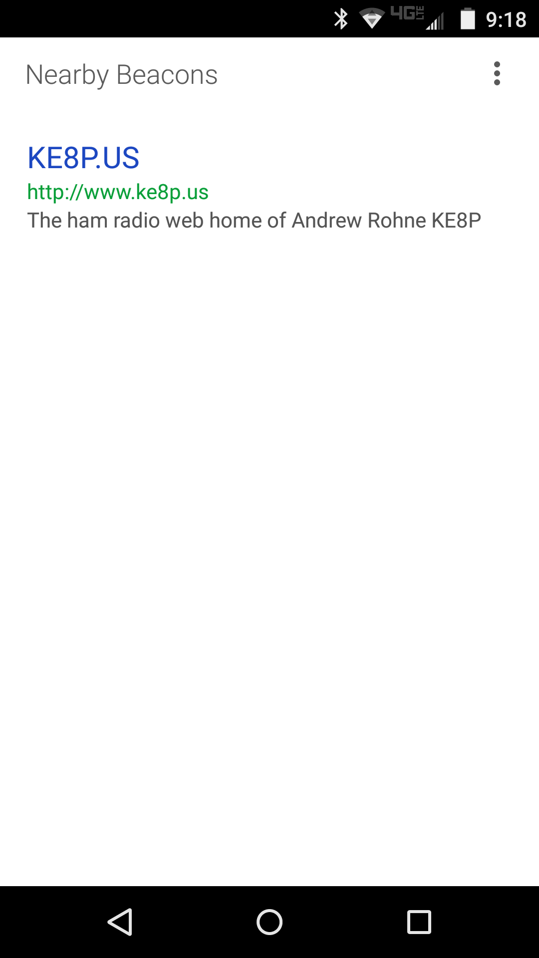
The app is fairly simple, but it works!
Where This Is Going
Rather than beacon a web URL, I imagine with the proper programming (on both the RFduino side and the Android app side), it could be used to pass a variety of messages. In fact, since the app looks up the description information, that could probably be used for simple messages (e.g. “the plant needs water”).
This has some pretty cool IoT and alerting uses. Stay tuned!
-73-
This is two out of four for me. I’m too busy.
So last year I had a number of things I wanted to do. Then my radio went kaput and I still haven’t fixed it. Other things happened, too.
This year I am definitely going to fix… or pay someone to fix my IC-706. I will probably get into FreeDV and maybe another digital voice mode. I want to build a receiver, too, and not from a kit.
I know there will be a lot more Arduino stuff going here, and there will be some FPGA stuff, too. I also have some electronics-but-not-ham stuff coming (some of which has no other blog of mine to go to, and some will be cross-posted from another one of my blogs).
I’ve been somewhat silent out here, but that shall change soon.
-73-
This is one of those “I keep needing this, so I bet it will help someone else” things.
A few months ago I purchased a “Basic Electronics Parts Kit” from Radio Shack (I’d have linked to it right there if I could find it, but sadly I cannot… it’s part number 09A12, which no longer shows up on Radio Shack’s website). In said part assortment is a handful of ICs, but it appears that they are only for those that have the important parts of the 4000 and 74LS series of ICs memorized. Since I am not one of those people, I looked up each one. Here’s the list and what they are:
LM386: Op Amp
NE555N: single timer
UA741CN: Op Amp
CD4013BD: Dual D-Type Flip-Flop (similar to 74LS74)
CD4017BD: Decade counter
UTC7805: 5V Linear Regulator
LM7812: 12V Linear Regulator
HD74LS00P: Quad 2-input NAND Gates
HD74LS02P: Quad 2-input NOR Gates
HD74LS08P: Quad 2-input AND Gates
HD74LS10P: Triple 3-input NAND Gates
HD74LS74AP: Dual Flip-Flop, D Type w/Set Reset
HD74LS86P: Quad 2-input XOR Gates
-73-
On the way back from a meeting, I dropped by the Columbus Micro Center Mall. I really didn’t know what I was looking for, but I figured I’d want to look at something for a project in the works (that involves an accelerometer or two), my Hack A Day Trinket Project, and anything else that looked good.
It was a good trip.
I grabbed a few (relatively expensive) breakouts for SOIC and SSOP chips, which I’ll ultimately use one for an SA602 mixer. I also grabbed a small pack of resistors, which will be in use for my HAD Trinket project. I found two accelerometers for $5 each (!!!). I grabbed a few PC boards. And the best part – a Yun for $55 (off their normal $75)!
I uploaded a microcontroller Hello World (a blinking LED) to the Yun via Wifi. It was awesome and convenient. The code is below, and it’ll work for any Arduino or clone (I initially wrote it for a Trinket).
In action on a Trinket:
And on a Yun (I used the onboard LED):
Next week, back to the normally scheduled DDS mischief.
-73-
A while back, I bought a few DDS modules through eBay. I used code from NR8O to program one of them and started pulling parts from the bin and pushing the output signal through the parts and into a load resistor.
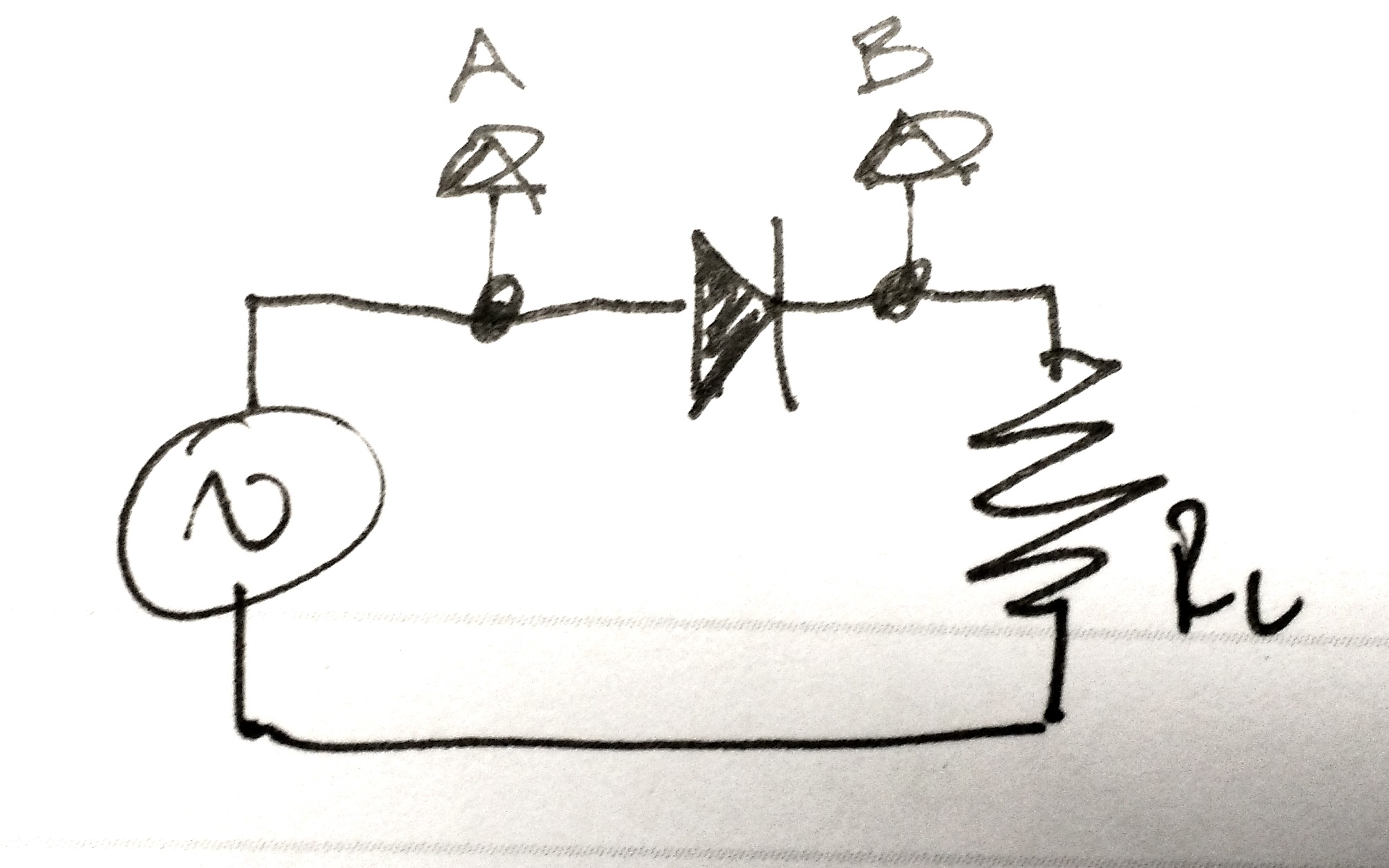
Experiment 1: Just a diode
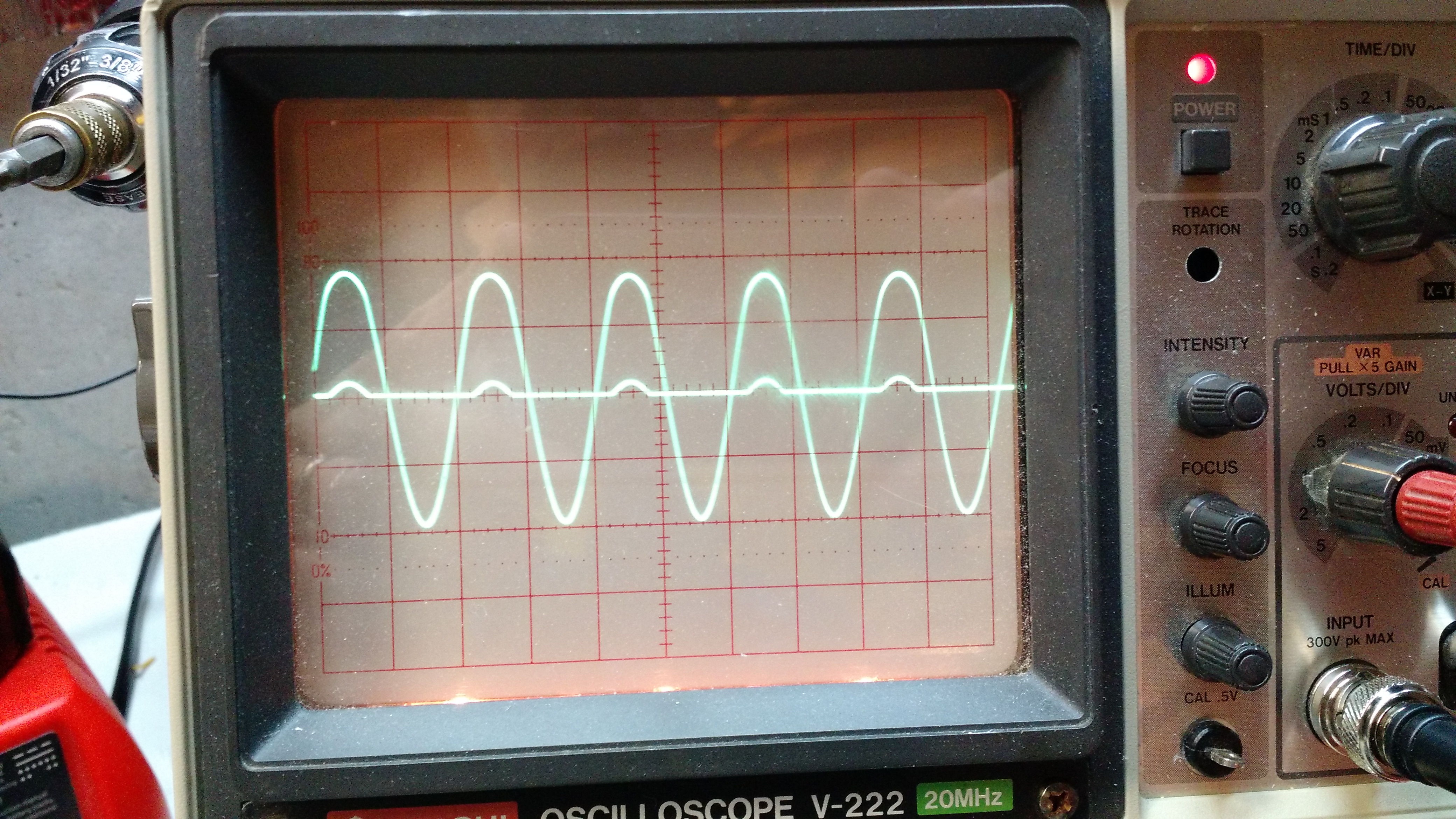
Result 1: the large waveform is the input signal (A), and the small bumps are the scope channel 2 (B). The diode rectifies the signal, which is why the bumps are only going up (and not down). The forward voltage drop on the diode is why the bumps are so small.

Experiment 2: a diode bridge
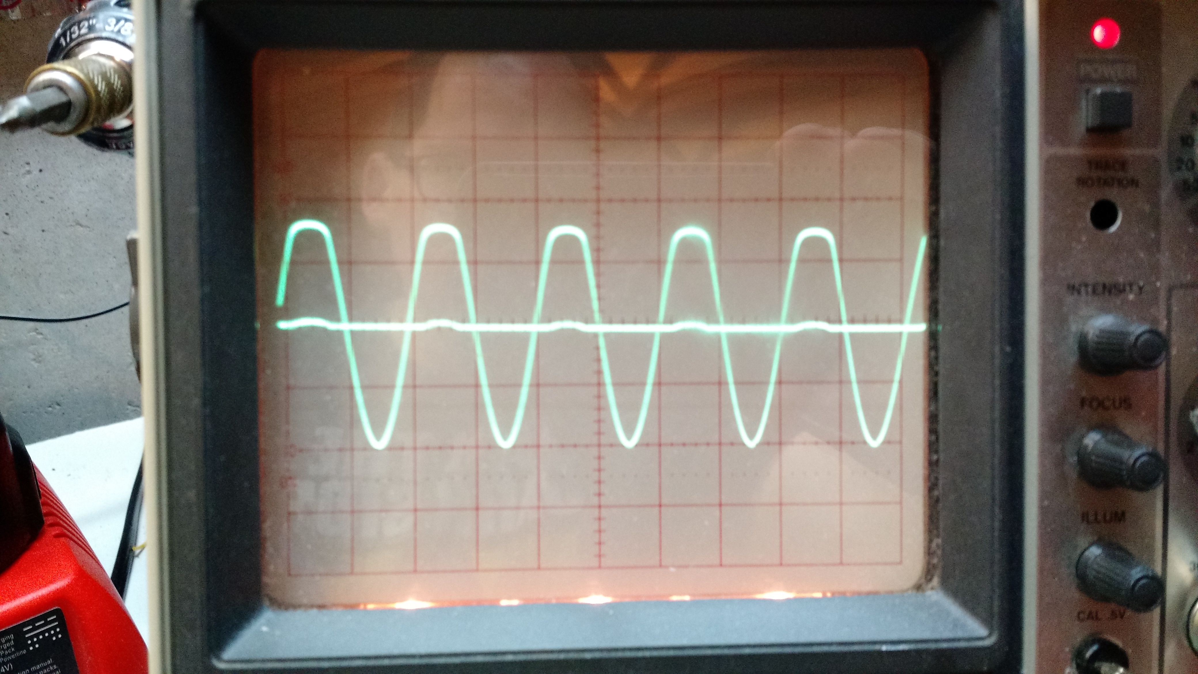
Result 2: This is similar to the circuit above, just more voltage drop because more diodes are involved.
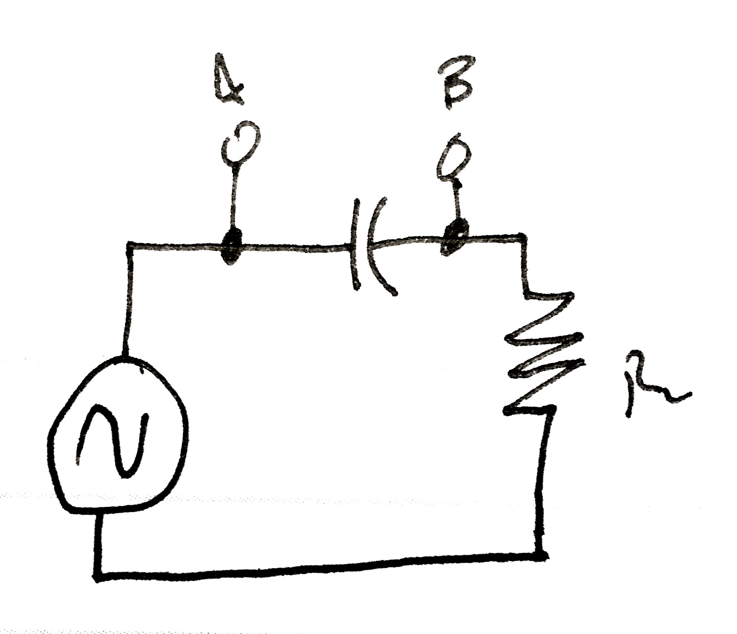
Experiment 3: Through a capacitor
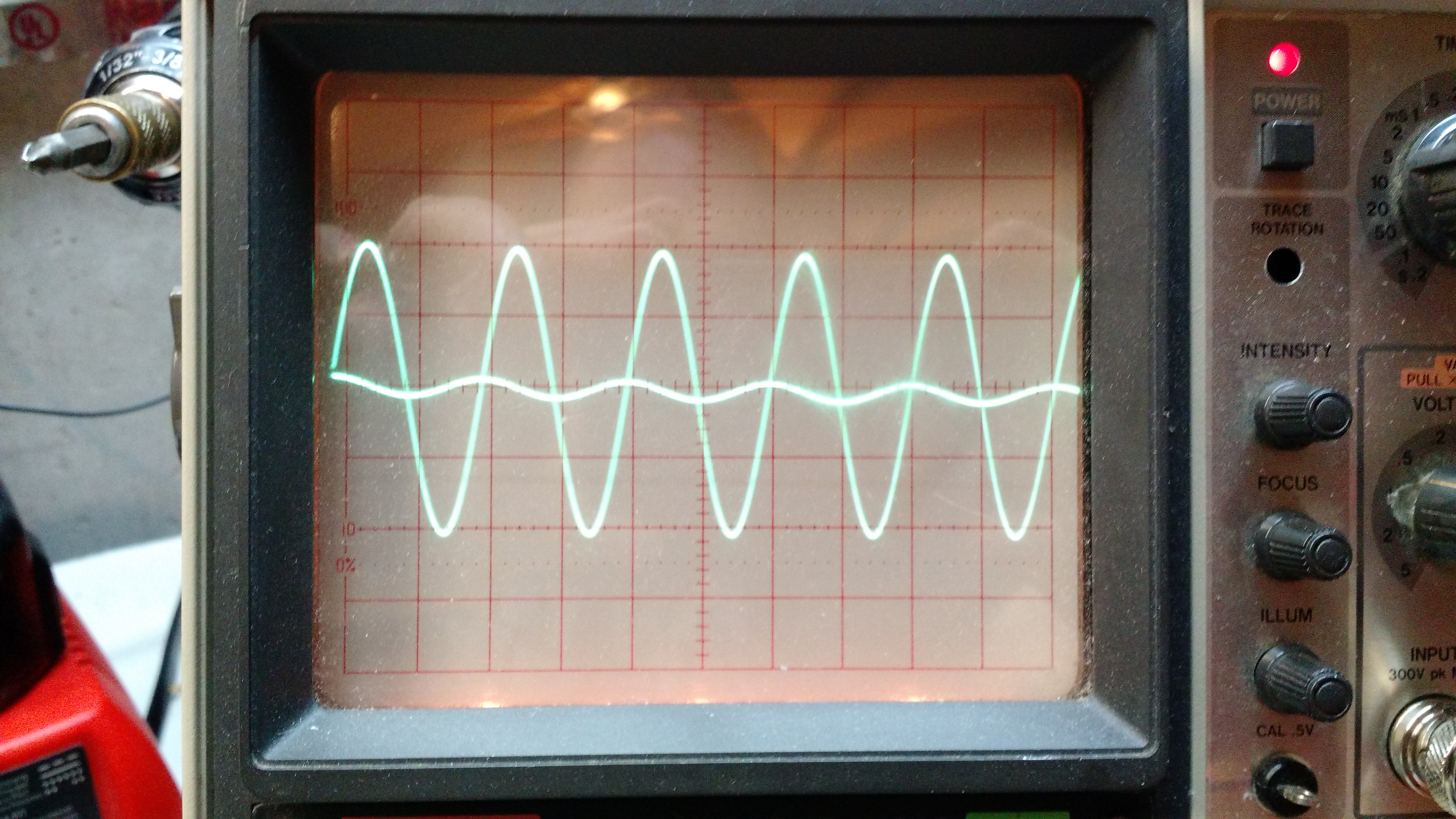
Result 3: the capacitor blocks DC, but allows AC through, with some voltage drop.
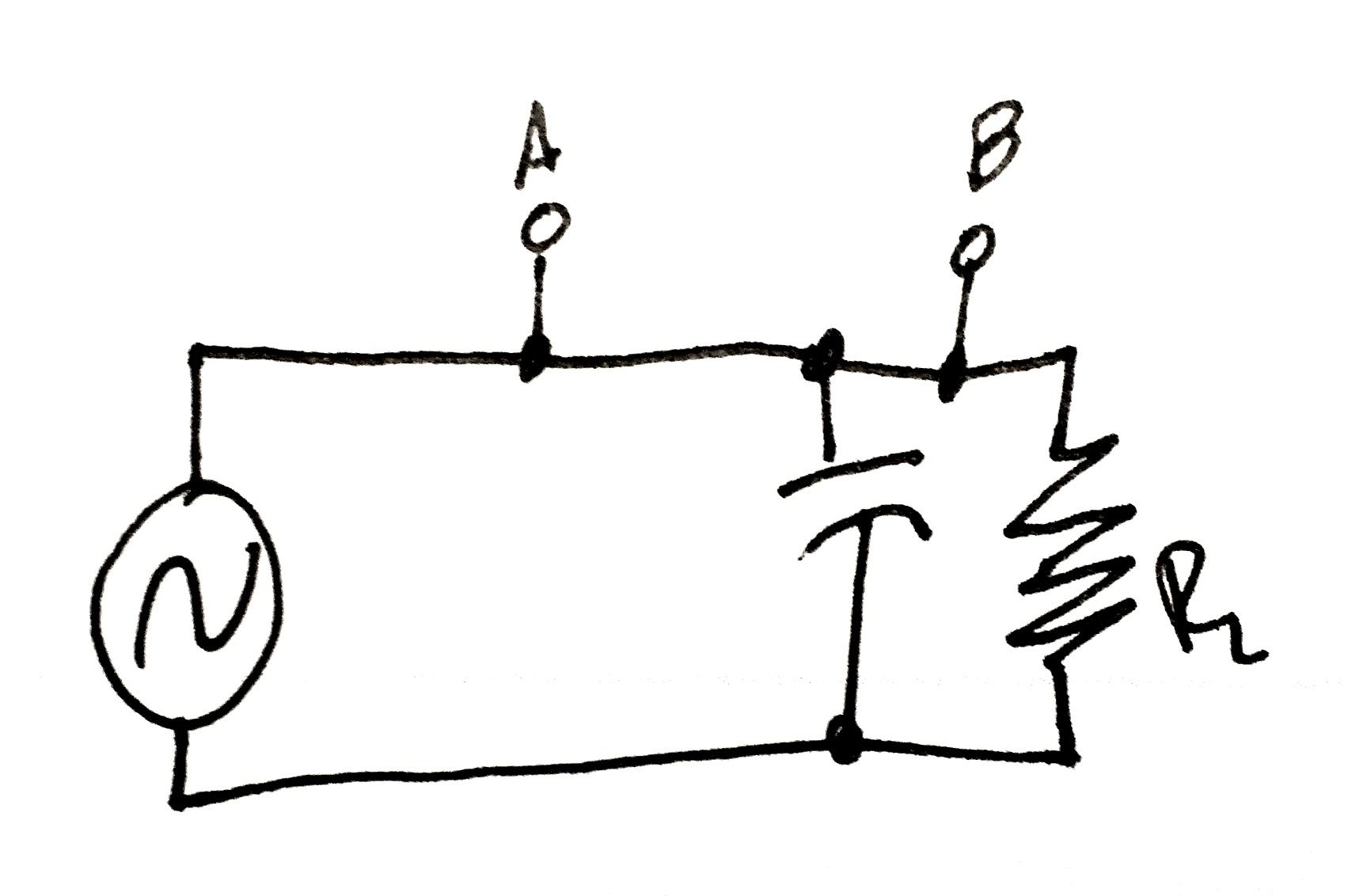
Experiment 4: Capacitor parallel with load.
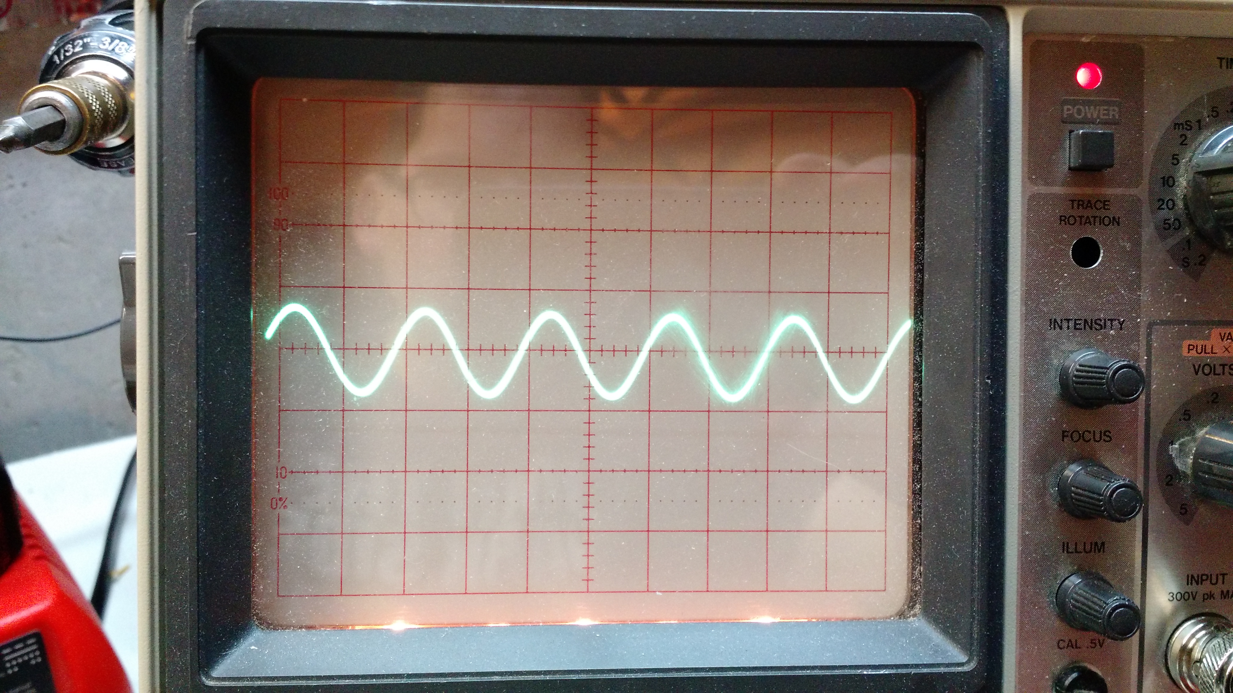
Result 4. No change because there is nothing between the test points.
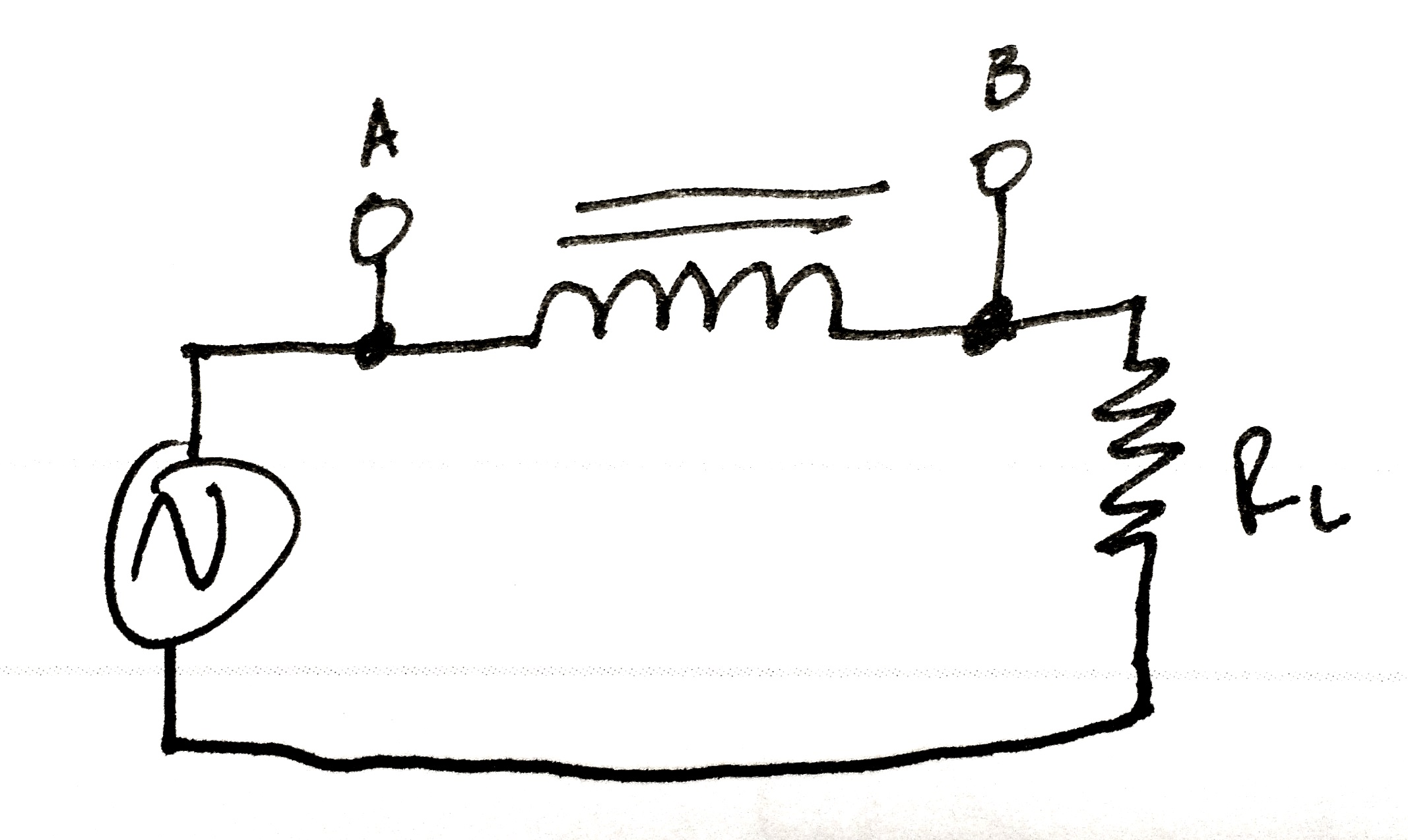
Experiment 5: through an inductor
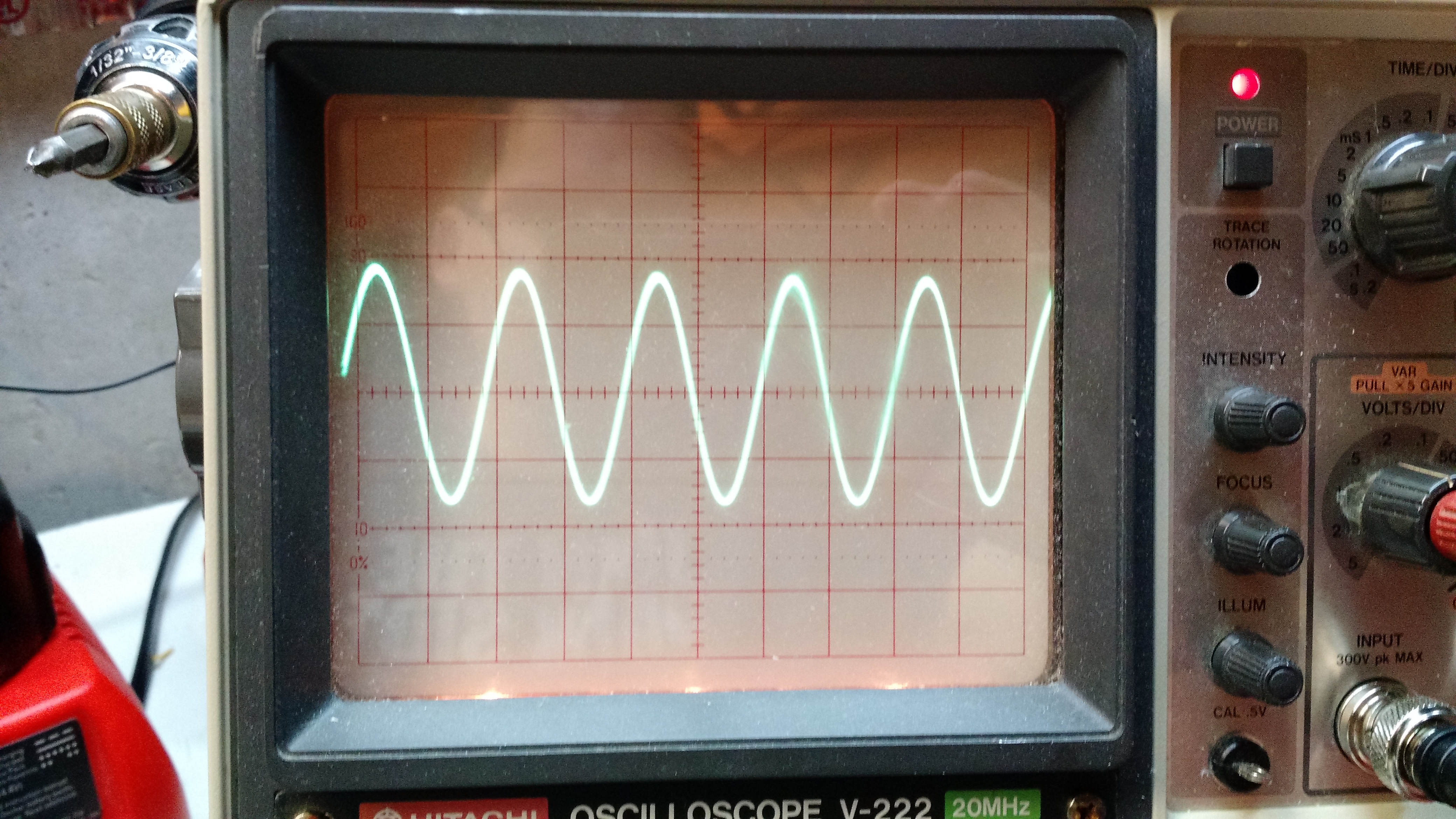
Result 5: there was no change.
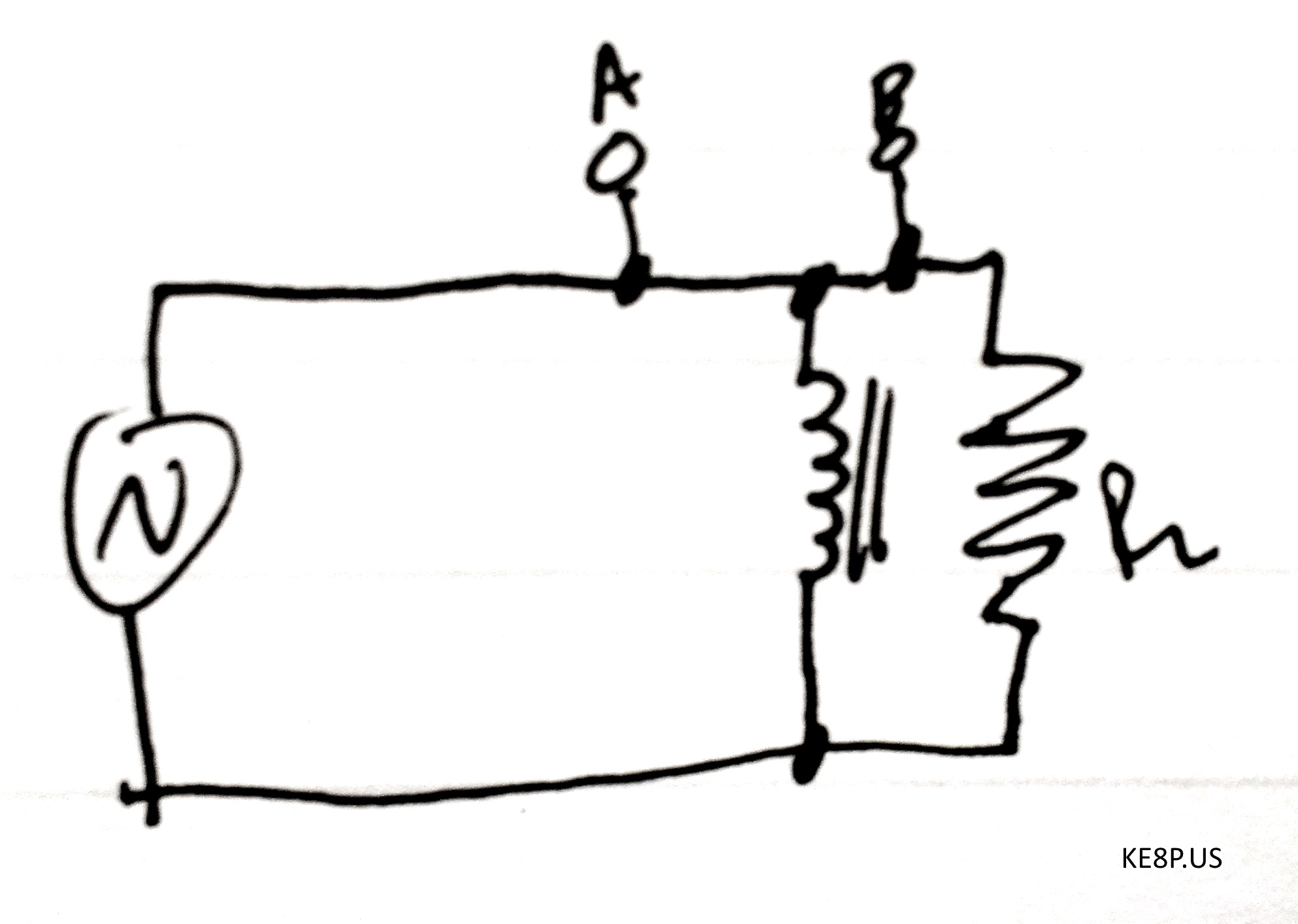
Experiment 6: inductive load
The video below shows what happened. I’m sure there’s an explanation of the instability, but I don’t know the explanation.
Stay tuned for experiments 2!
73 de KE8P
While it appears I have not been affected, there is proof that QRZnow (NOT TO BE CONFUSED WITH QRZ.COM) is stealing content. Details can be found on Reddit. A real-world story can be seen on NT1K’s website.
Please do not support the thieves. Seek out the original authors and support them.
I’ve run into a situation where I need to be able to read a temperature with my Beaglebone Black (I really don’t care about humidity). After setting up the sensor on my Rpi, a few have emailed me and asked about doing the same for a BBB, and I haven’t had much by way of response. The file that I previously used didn’t work on a BBB.
On the Beaglebone Black, there are a few preparation items that must be completed:
1: Make sure you have Internet connectivity (I had to add DNS servers to /etc/resolv.conf)
2: Go to Derek Molloy’s blog and follow step 3 under “Fixing SSL Problems with Curl”
3: Make sure Python and some Python tools are installed:
opkg install python

opkg install python-pip python-setuptools python-smbus python-misc
4: Install the Adafruit BBIO Python tools:
pip install Adafruit_BBIO
5: Follow LadyAda’s steps to install
At this point, you can connect the sensor, make sure to use SYS_5V (P9 7 or 8) and not VDD_5V.
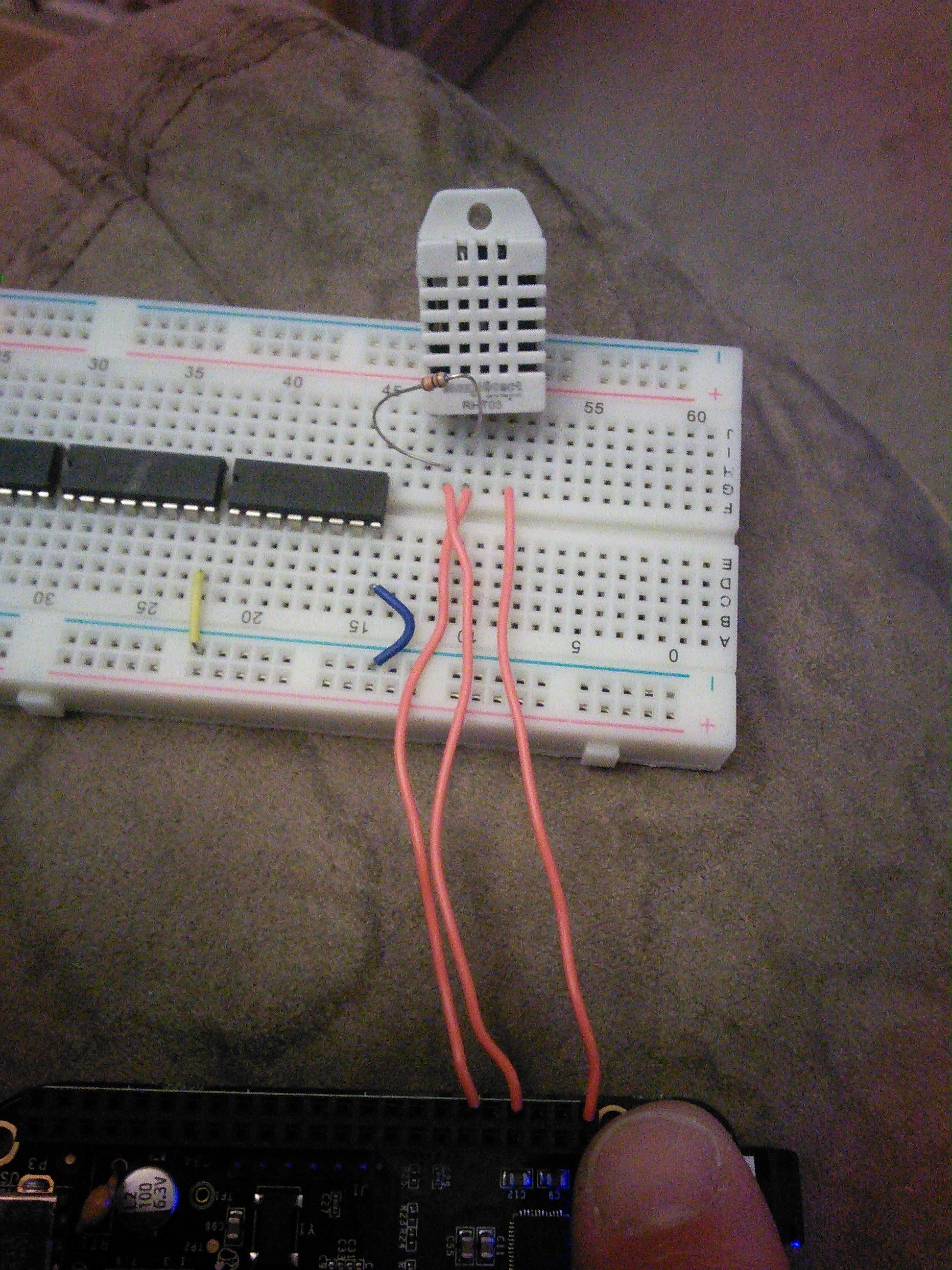
Pin 1 on the sensor is connected to P9_7, pin 2 has a 10K pullup resistor and is connected to P9_11, pin 3 is connected to P9_1.
At this point, you can go into the examples and it should work… in Centigrade:
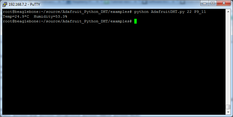
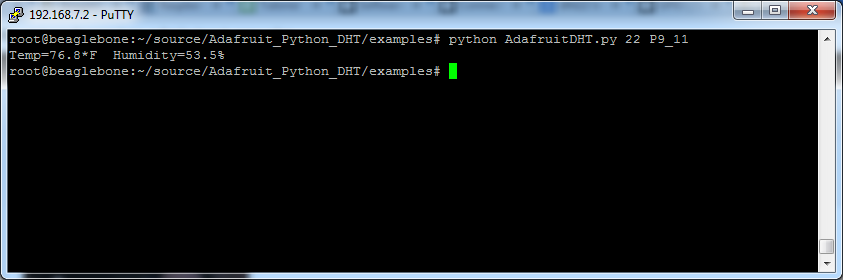
…which is great for those of you that use that standard, but in America we use Fahrenheit, which is a pretty simple code change that you can see in my fork on Github.
So now…
At this point, a mix of Python and Cron would make this able to send data to ThingSpeak, Xively, Phant, or any of the other IOT logging services (which may become a future blog post).
-73-
PS: for full disclosure, I’m looking at this because I’ve been brewing beer and I’d like to THINK my basement temperature is under control, but with temperatures possibly starting to fall in my area I’d like to keep a better eye on it. 🙂
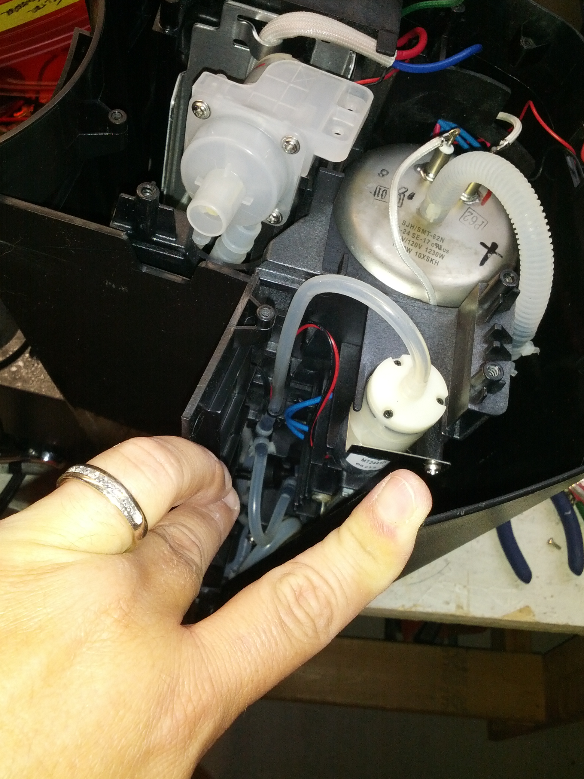
Yesterday I tore into a Keurig machine that I saved from a landfill. The machine no longer worked and I don’t really even recall what, but I have another Keurig that collects dust (I use a drip coffee maker), so why not.
-
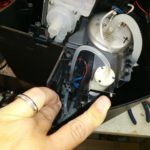
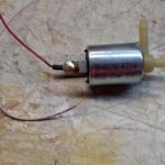
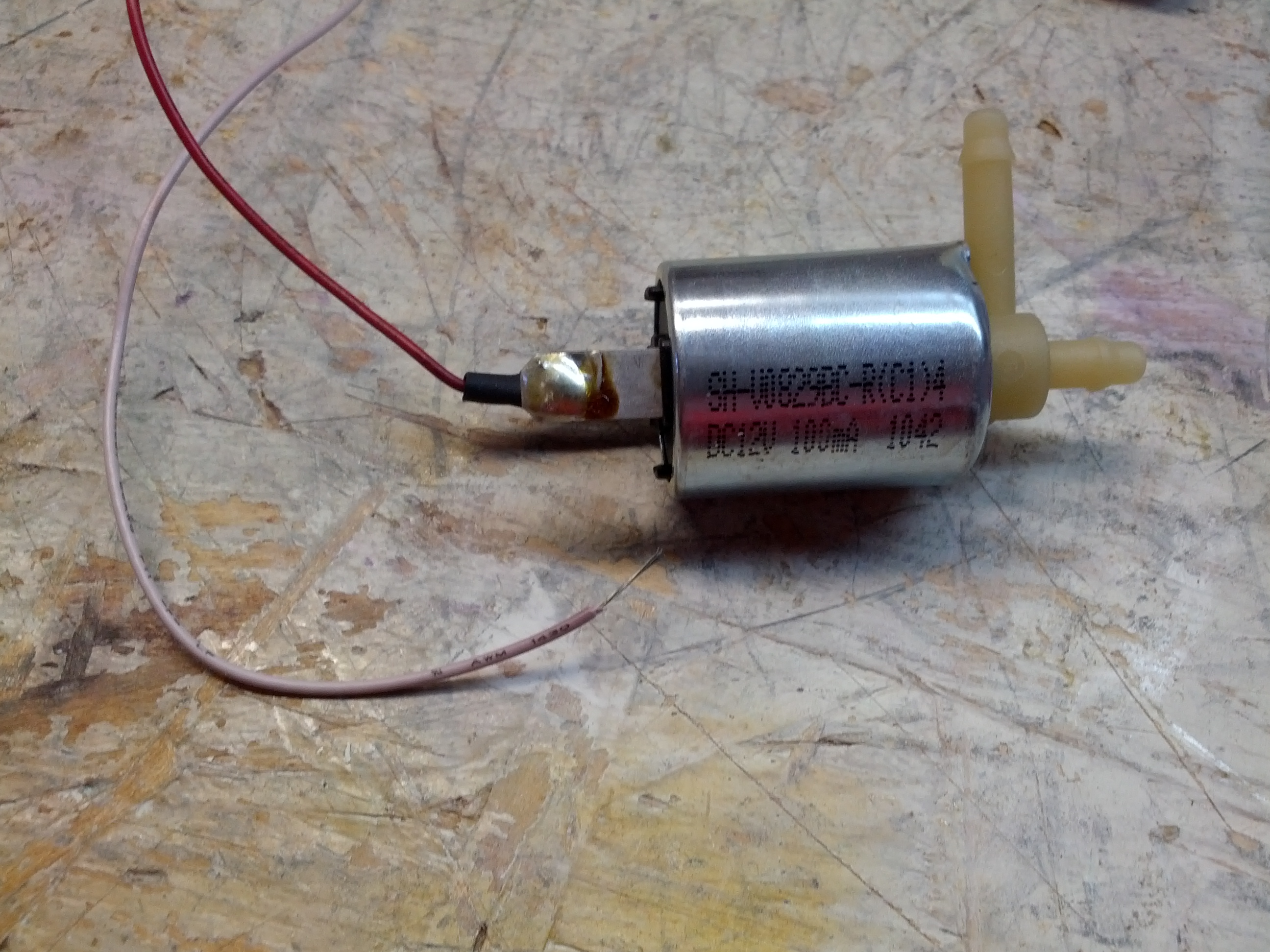
- Lower (main) pump below the tank as well as an aerator (near my finger).
-
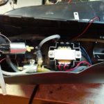
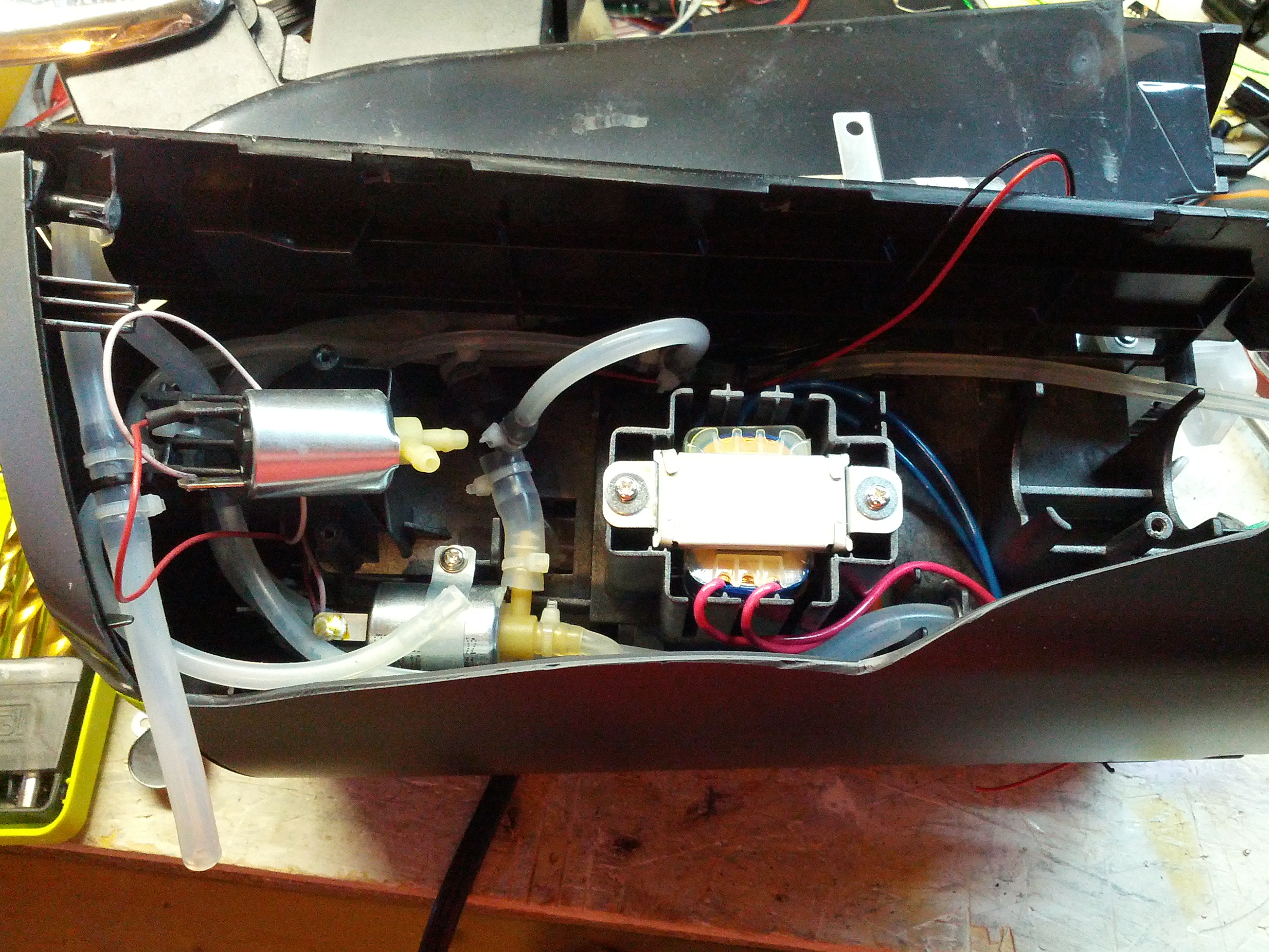
- Transformer and two of the pumps.
-
- Where there’s water it will leak on your workbench, and shirt before you get a coffee can under it.
-
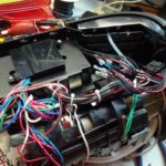
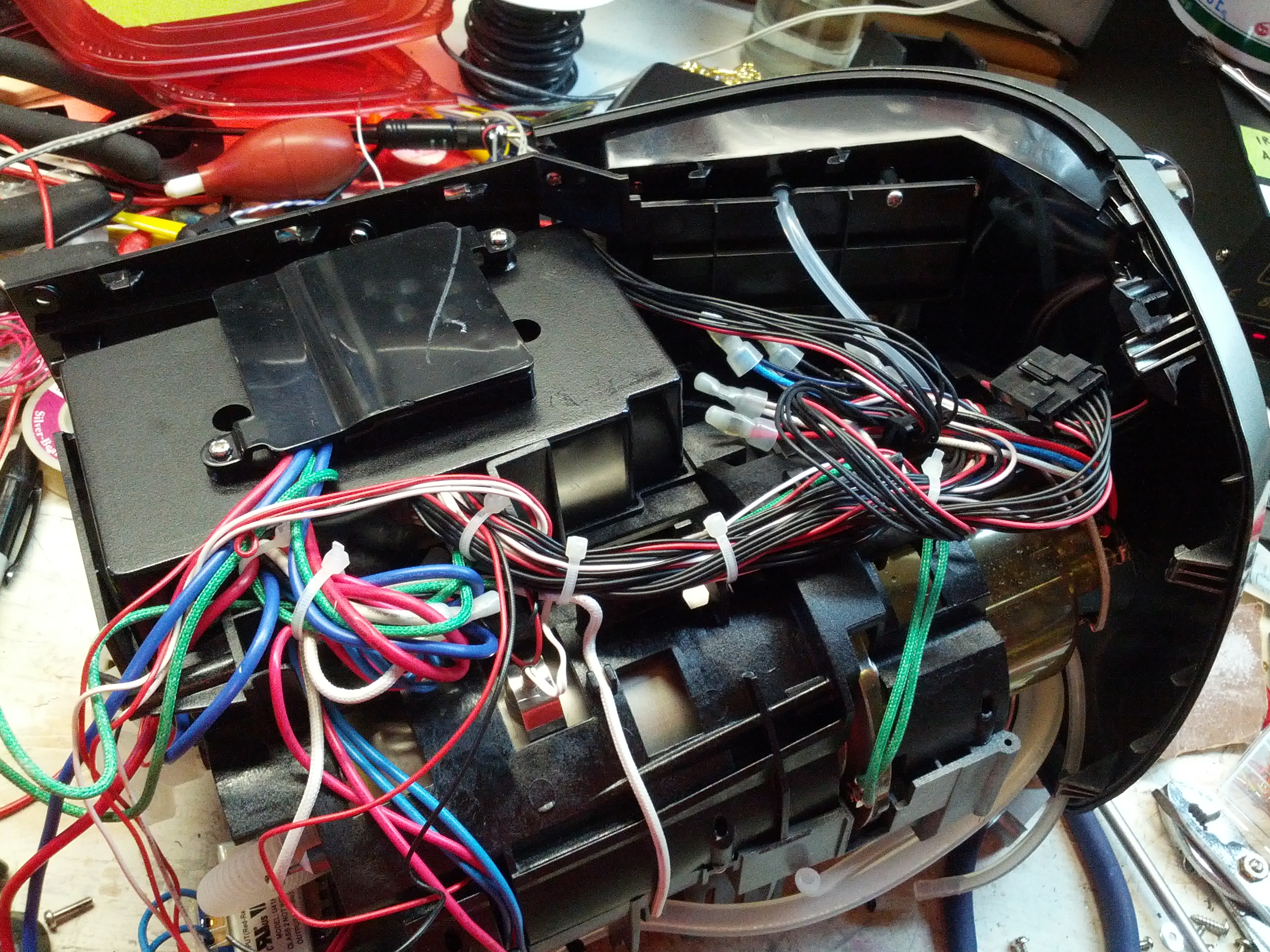
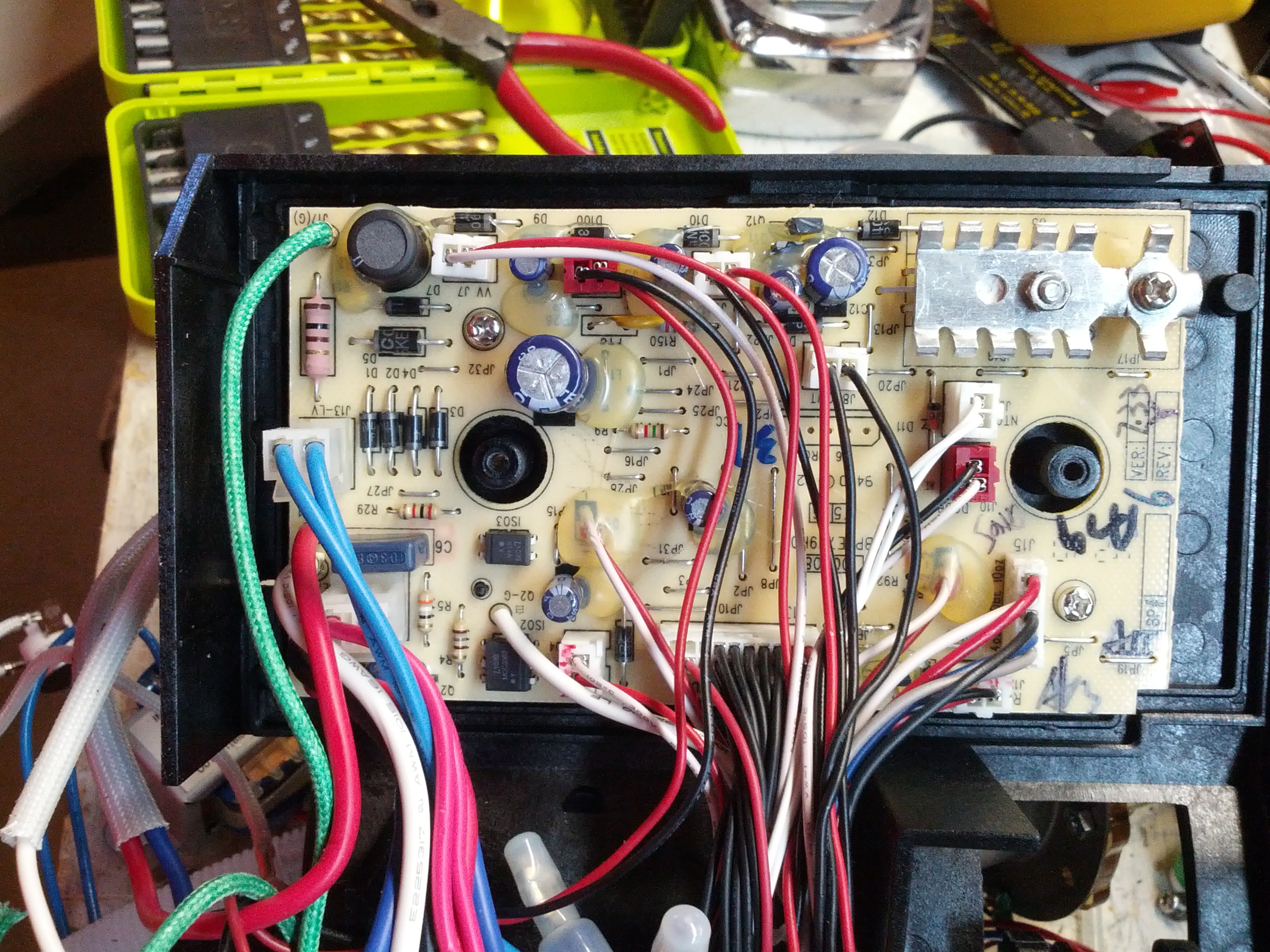
- Lots of wires.
-
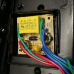
- Power driver.
-
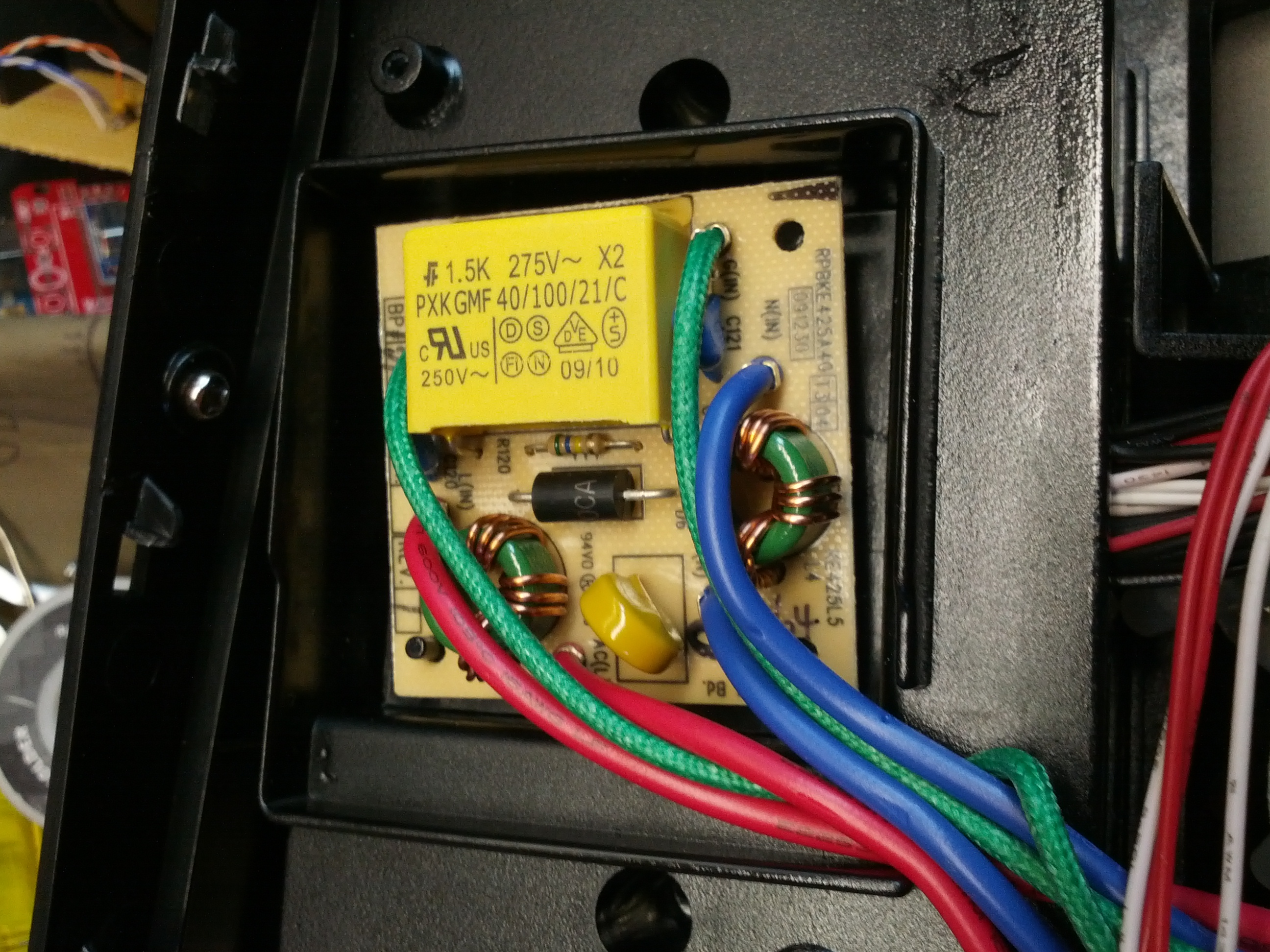
- Top of the tank still in the chassis.
-
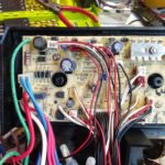
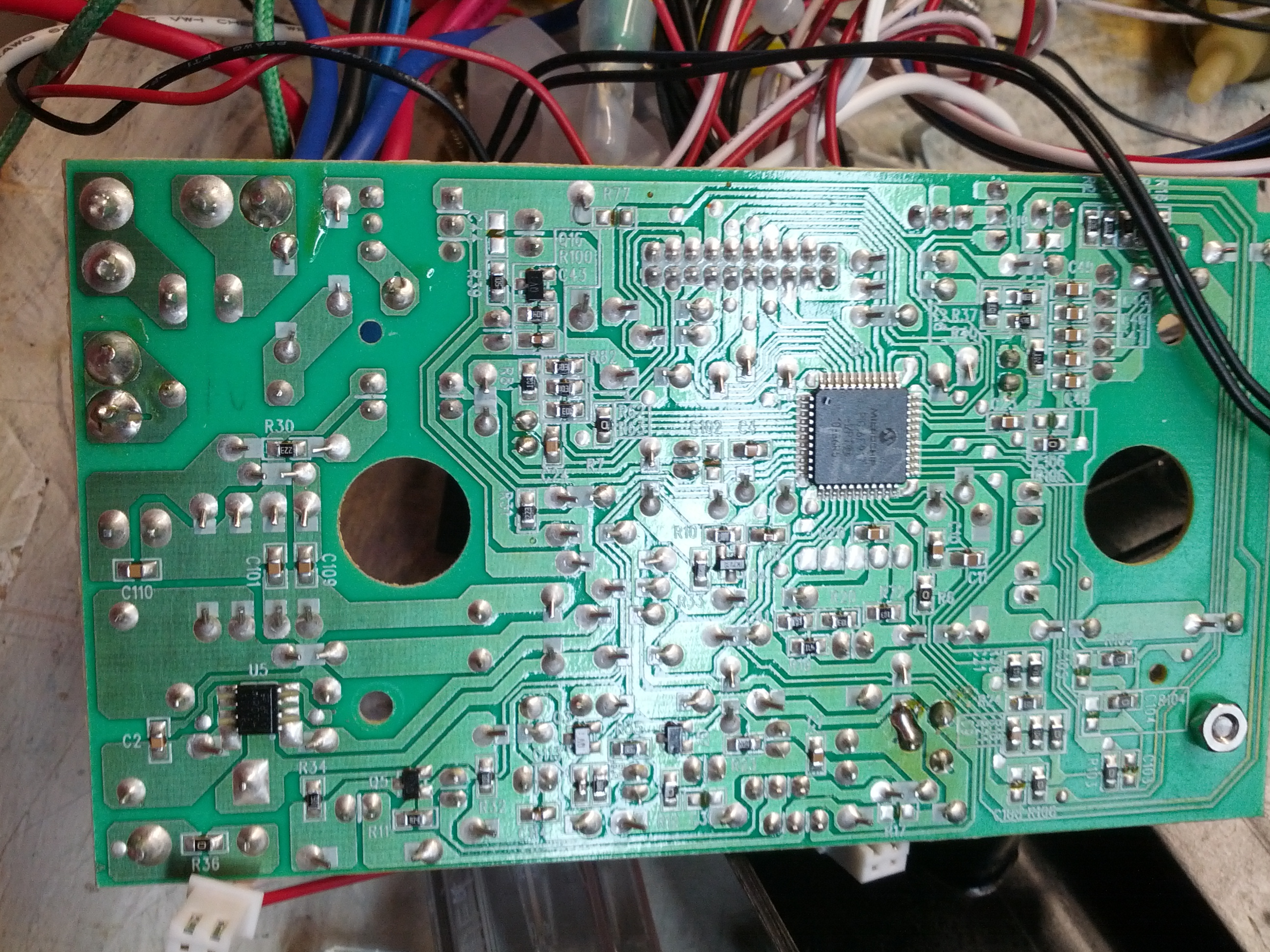
- Mainboard.
-
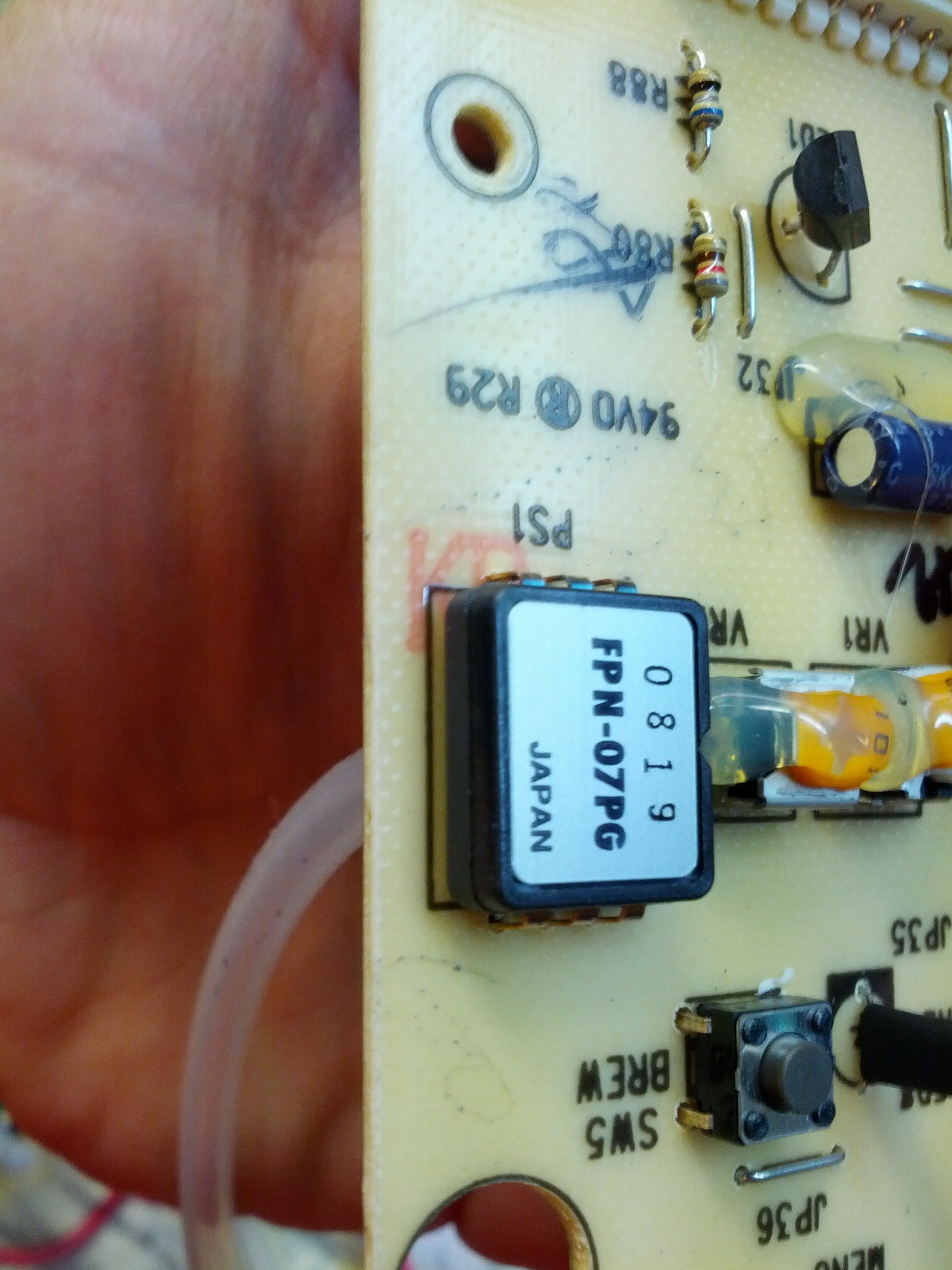
- Brains of the operation: a PIC16.
-
- Pressure sensor.
-
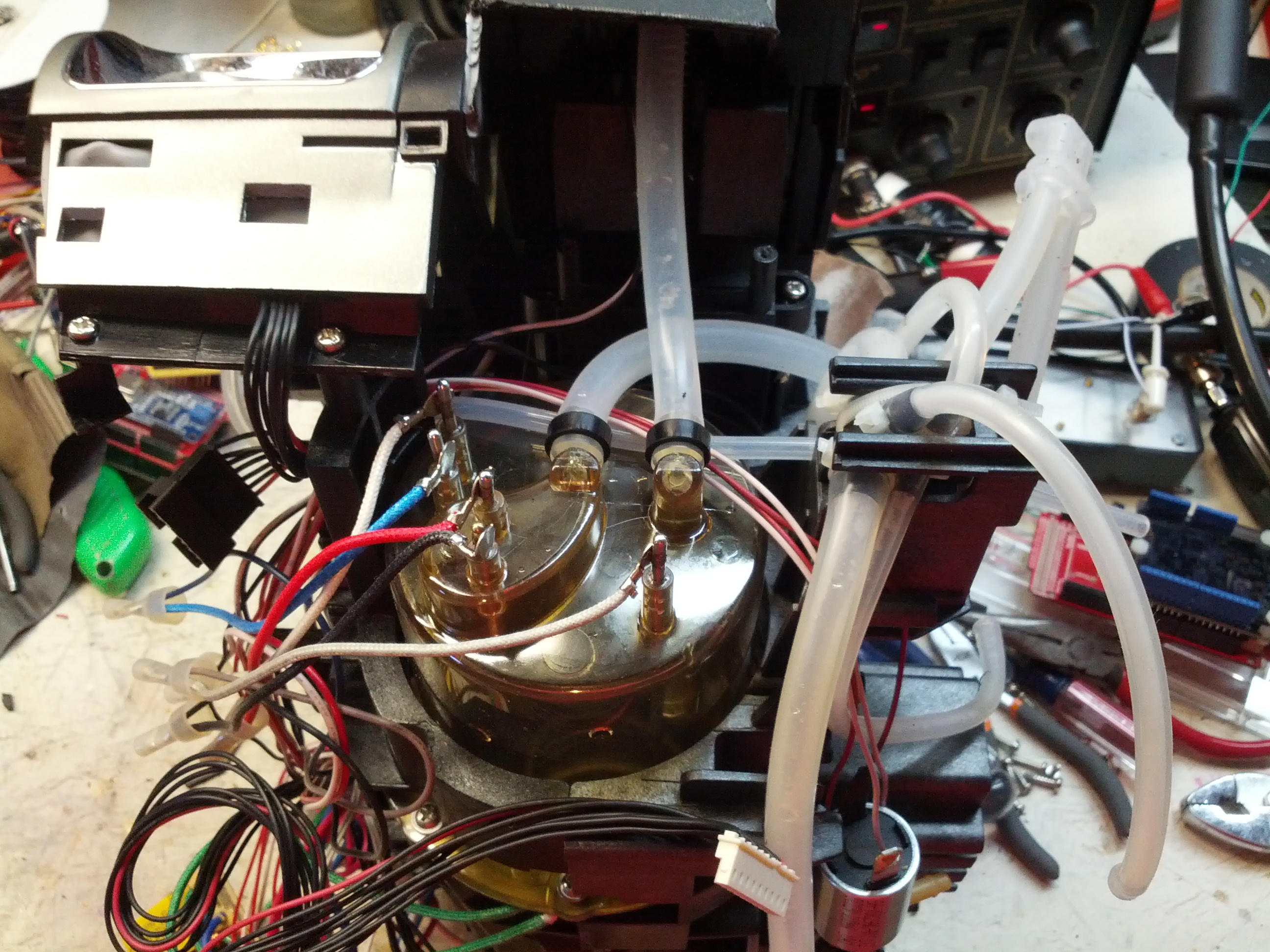
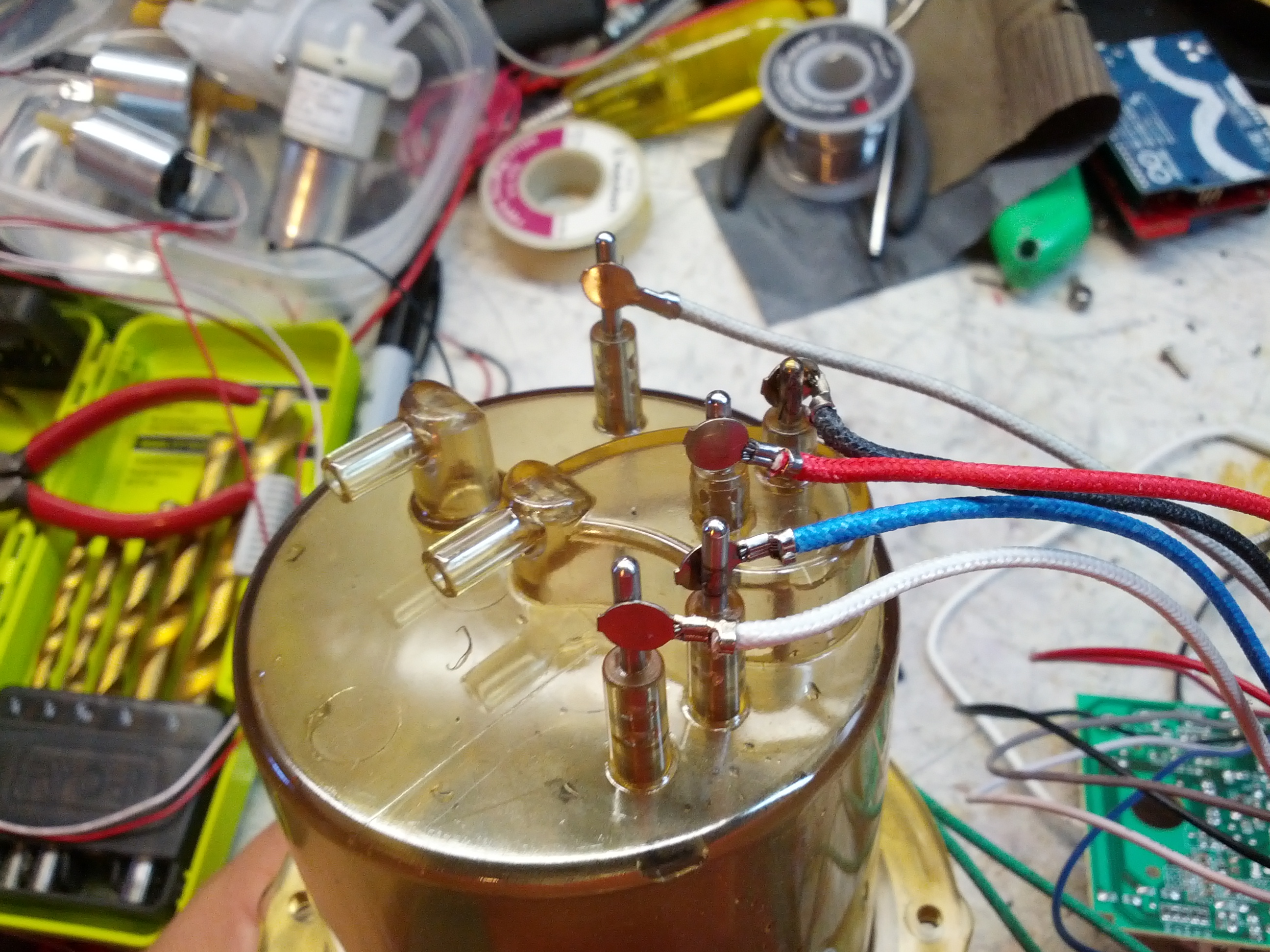
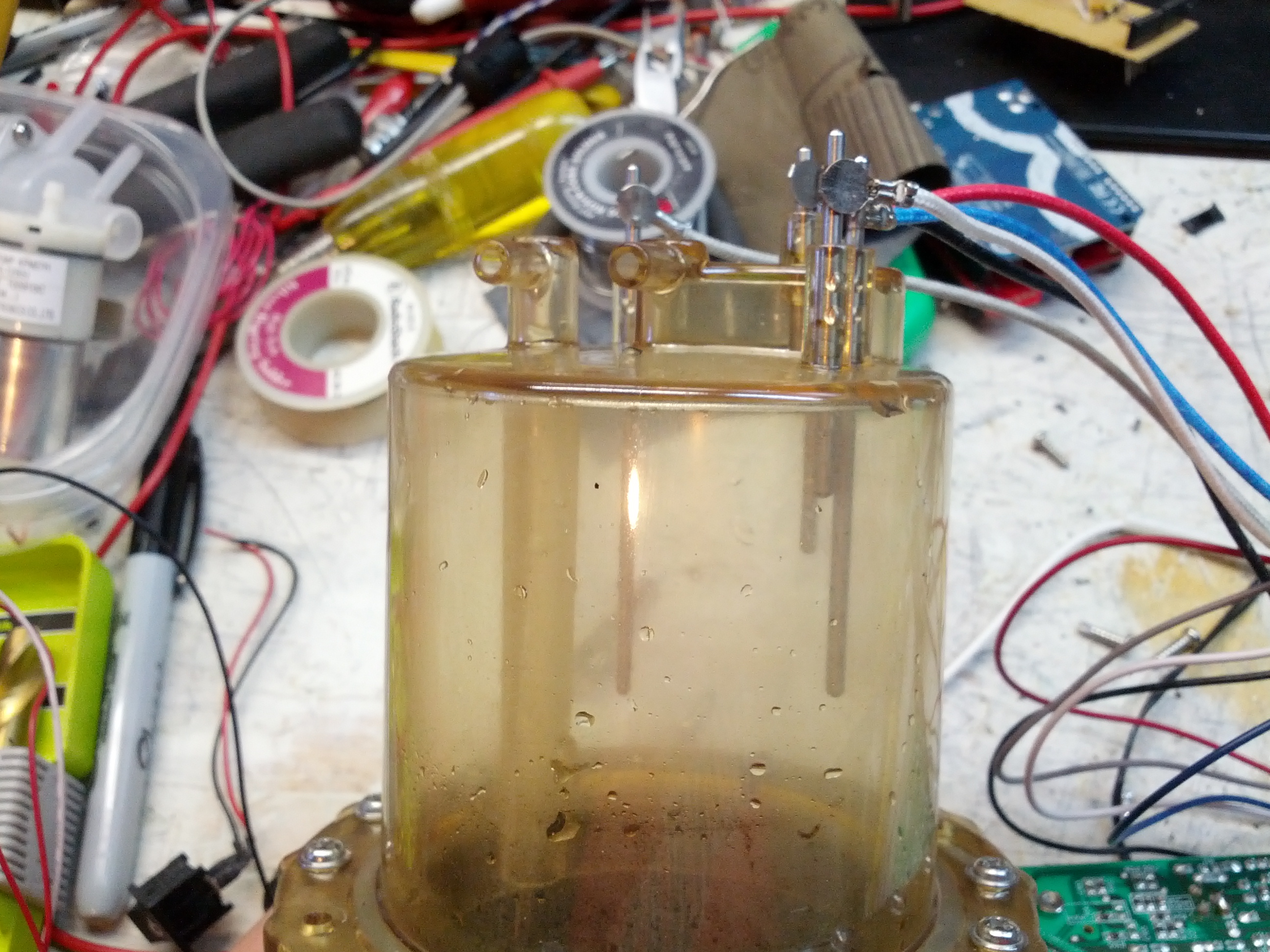
- Top of the tank.
-
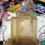
- Sensor probes. I believe there are two different sensors here for sensing water level (one low and high, and the other for sensing an overflow).
-
- This may have been part of the problem.
Thoughts:
- This could be the beginning of something, I’m not sure what though
- I now have two check valves and three pumps. One of those pumps works (the other two, I’m not so sure). These are not self-priming pumps. Two of the pumps and the aerator are marked at 100 mA, which is nice and low but still too much to be driven directly from an Arduino pin.
- The tank can be pretty useful. It has a thermocouple and overheat switch on the side, a heating element at the bottom, and several probes on the top.
- This is dangerous work. Lots of sharp plastic. I’m fairly certain these were made to be assembled only.
One of the things I was looking into is a digital compass module. These are modules that return a direction it is pointing relative to magnetic north.
I started by using the Bus Pirate to access and read the module. I did that as below:
m <– for menu
4 <– for I2C
3 <– for 100KHz
I2C>(1) <– I2C Address Search
Searching I2C address space. Found devices at:
0x3C(0x1E W) 0x3D(0x1E R)
I2C>[0x3c 0x00 0x70] <–Set measurement mode to 8-average, 15Hz
I2C START BIT
WRITE: 0x3C ACK
WRITE: 0x00 ACK
WRITE: 0x70 ACK
I2C STOP BIT
I2C>[0x3c 0x01 0xa0] <– Set gain to 5
I2C START BIT
WRITE: 0x3C ACK
WRITE: 0x01 ACK
WRITE: 0xA0 ACK
I2C STOP BIT
I2C>[0x3c 0x02 0x01] <– Set to single-measurement mode
I2C START BIT
WRITE: 0x3C ACK
WRITE: 0x02 ACK
WRITE: 0x01 ACK
I2C STOP BIT
I2C>[0x3d r:6] <– Read 6 bytes
I2C START BIT
WRITE: 0x3D ACK
READ: 0xFF ACK 0xFD ACK 0xFF ACK 0x98 ACK 0x00 ACK 0x5F
NACK
I2C STOP BIT
This returned 0xFF, 0xFD for X, 0xFF, 0x98 for Y, and 0x00, 0x5F for Z. This is Twos Compliment Form, which is best explained by this Stack Overflow Community Wiki.
X Coordinate (0xFF): Binary 1111 1111 + 0xFD: Binary 1111 1101
Y Coordinate (0xFF): Binary 1111 1001 + 0x98: Binary 1001 1000
Z Coordinate (0x00): Binary 0000 0000 + 0x5F: Binary 0101 1111
Ultimately, this is where I stopped. I know it works, I have some ideas on how changes affect it. Now on to an Arduino.
Arduino Micro Setup
I plugged this into an Arduino Micro on a breadboard as below. The 5V, ground, pin 2/SDA, and pin 3/SCL were connected as shown (note that the compass on the left can be ignored – I have two and they are both in the breadboard just to keep them somewhere safe).
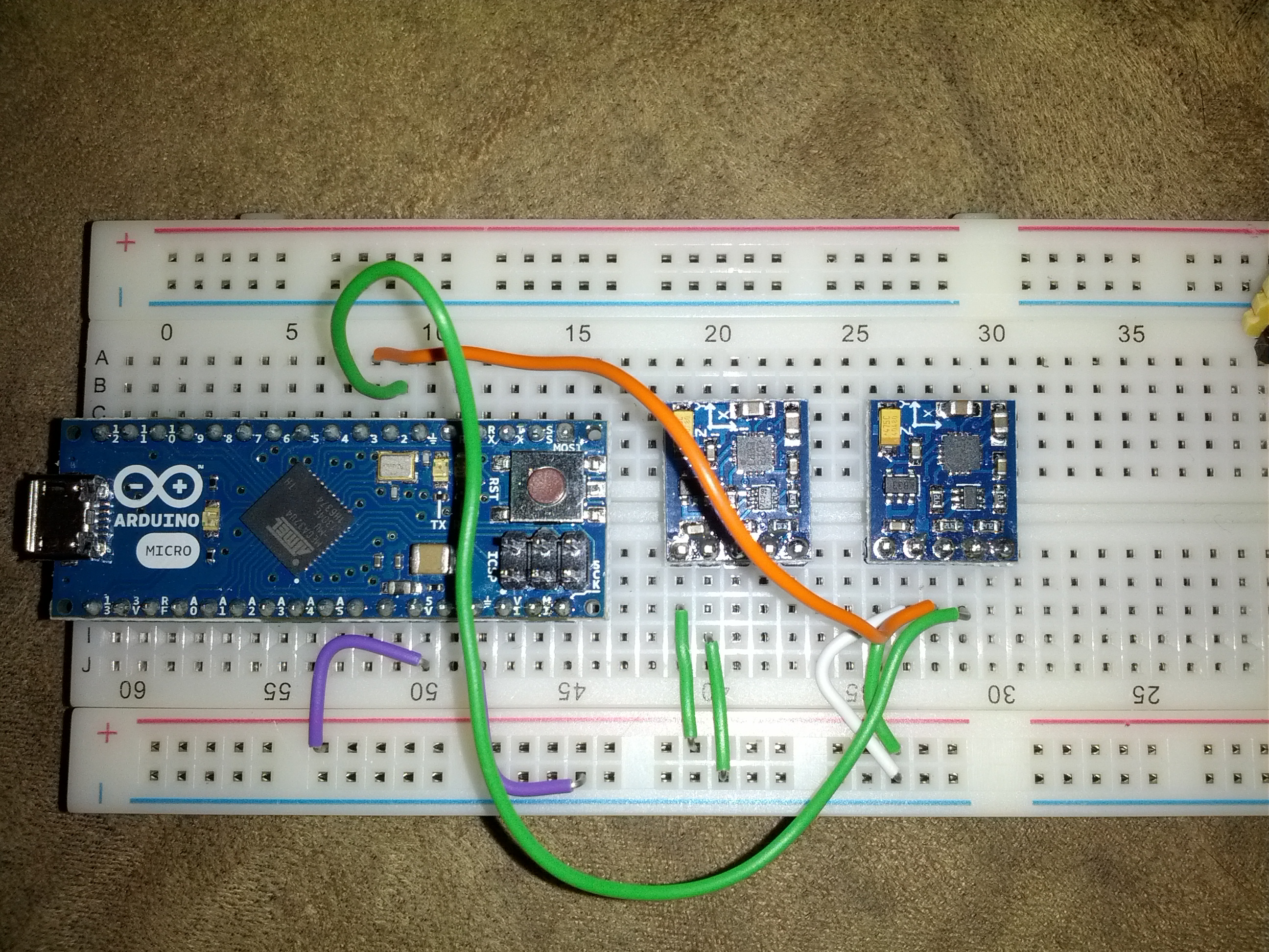
One of the more difficult parts of this is ensuring you’re in the correct pins on the Micro – the numbers are small and not centered on the pin.
The code is below. I started with code from Sparkfun and modified it as necessary.
Right now, this is functional. There will be more to come.
-73-