
Tag Archives: ad9850
I’m not going to call it a spectrum analyzer anymore – the way I’ve designed this, it isn’t going to do the same things as a spectrum analyzer.
The main difference is that a spectrum analyzer can operate without a signal generator, this won’t because the signal generator is what is going to tell the Arduino what the frequency is.
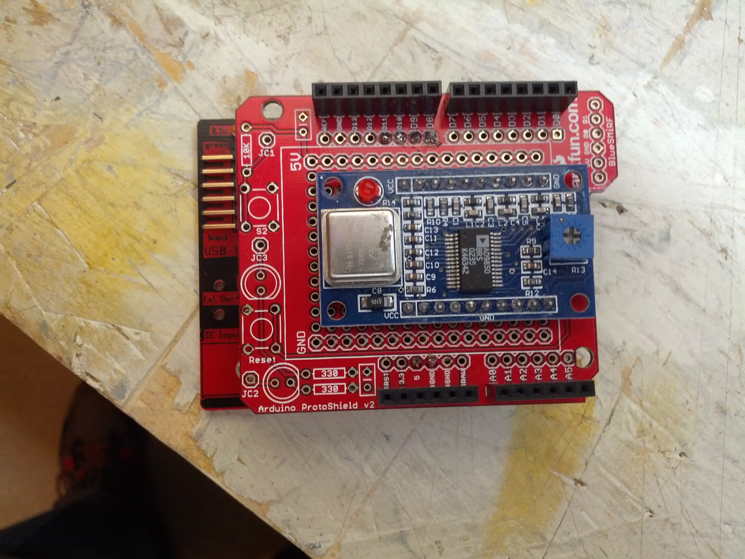
I built another shield to stack onto the shield in last week’s post.

There is currently no connection from the DDS to this yet, but that’s one of the only few things left to do on the hardware side.
I also built a filter that will ultimately be the first filter to test. This is for my Softrock 20/30/40 and should pass 7 MHz while filtering 14 MHz.

This will fit in a Radio Shack small plastic enclosure – the plate was leftover from a small dummy load that I glued into the enclosure.
-73-
I’ve been reading a lot about receivers, and it sounds like one important thing is filtering. It makes sense too – simple receivers can suffer from front end overload due to a strong signal. And when on the ham bands, you never know where that strong signal may be – it could be someone driving down the road (which is a bit obvious once you see it), but in my neighborhood, if you don’t know me, you’re probably not going to know about the antennas in my attic.
I don’t have a spectrum analyzer, and since I’m a traffic engineer, I really don’t have access to one. I don’t need a full-blown spectrum analyzer, either, I just need to sweep through the HF band and get the difference between signal input and output. Math will take care of the rest.
$$dB=20*\log{\frac{V_{out}}{V_{in}}$$
The way I figure it is this:
An Arduino (and this could become a Raspberry Pi or any number of other devices, but I’m going to use an Arduino because it’s cheap and relatively durable) controls a direct digital synthesizer (DDS) module that just scans through it’s limits… well, probably something like 0.5 MHz – 40 MHz – that gets me into the AM broadcast band (which can be a source of strong signals) to above the 10m band (I don’t know what’s up there, but whatever’s there is probably not running 50,000 watts).
The output of the DDS would have an RF voltmeter and a probe to go to a filter. There would be another RF voltmeter to sense a filter output. The Arduino would handle not only control, of the DDS, but also sensing the voltage.
It’ll look something like this:
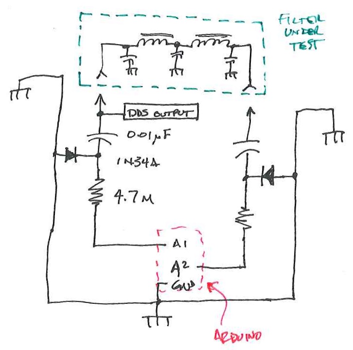
This is a block diagram/schematic of how this will work. I didn’t include the DDS module, which would be tied in there somewhere.
The Arduino and DDS will look like this:
There will have to be a companion app to this. In Java (not just because I’m drinking coffee, but also because it’s cross-platform). It’ll look like this:
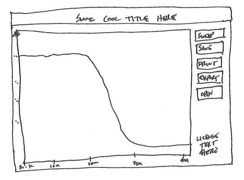
This is likely how things would look. Simple. A button that tells the Arduino to sweep, and some other important buttons.
I have the perfect item to test with also. One thing I built and don’t use (and never truly finished) was my Softrock RXTX. I need to build a filter for the output to keep the harmonic of the 7 Mhz fundamental from being too strong on the 20 meter band. I wound the coils while watching the Super Bowl-over-the-Broncos and printed a circuit board just before the game started.
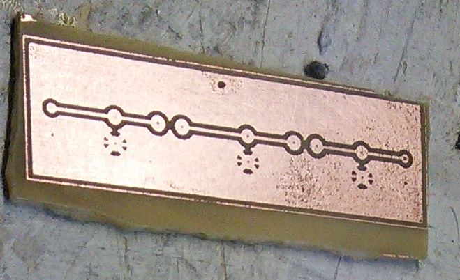
Easy and small, but for 0.95 Watts, you don’t really need much.
I’m not really sure if this will work, but it certainly seems like it would, and I think it would be interesting to see how some filters respond on this compared to a real spectrum analyzer.
-73-
After reading a few blog posts out there from others, I decided that it would be interesting for me to get hold of an AD9851 module. My initial plan is to build an antenna analyzer and something else (I bought two).
The major engine of these modules is an AD9850 Direct Digital Synthesizer. This chip can be purchased in quantity for $15.25 EACH from Newark. From Digi-key, $15.37.
The two modules I purchased on eBay were $8.90. Total. With shipping.
And these modules aren’t just the chip…
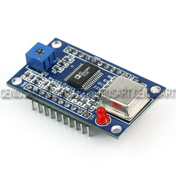
So I don’t totally understand how this eBay seller makes money, but it appears he does (it appears he’s/she’s sold quite a few of them, based on their eBay feedback rating). What I do (now) understand is why we no longer do electronics manufacturing in the USA.
After ordering this (at the time of writing, I’m still waiting on shipping), I started looking in to adding Ethernet capabilities to one of my Arduinos. So I looked in to the ENC28J60-based chipsets. After finding one for £22.90 and one for $35 on Sparkfun, I looked on eBay. $4.09 each from Hong Kong. $2 for shipping. At least this isn’t as egregious as the AD9850 modules, as the ENC28J60 chip is $2.36 in quantity from Digi-Key.
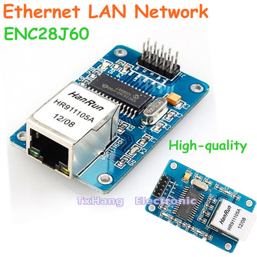
I can’t imagine this is news to anyone in the electronics industry, but I’m just an amateur radio operator and traffic engineer. I found this interesting. And I’m not complaining, as long as this stuff I get from China works! 🙂
Of course, there is a drawback to this – the wait. I got a confirmation of shipment for the DDS modules on March 26, 2013, and they arrived on April 6, 2013. I ordered the Ethernet modules on April 5, 2013, and they have yet to arrive. So there is a delay, but with some planning, a hobbyist like me can deal with it.
-73-
—UPDATE—
The Soldersmoke Daily News blog has another possible reason: a design flaw. See his post for details.