
Tag Archives: antenna
I don’t have much to post, and with weekends being nearly as busy as weekdays, I haven’t had much time to get into anything, but I did get some time working in the shack on a Par style end fed antenna. I started thinking about this and worked off the design on W0EA’s blog.
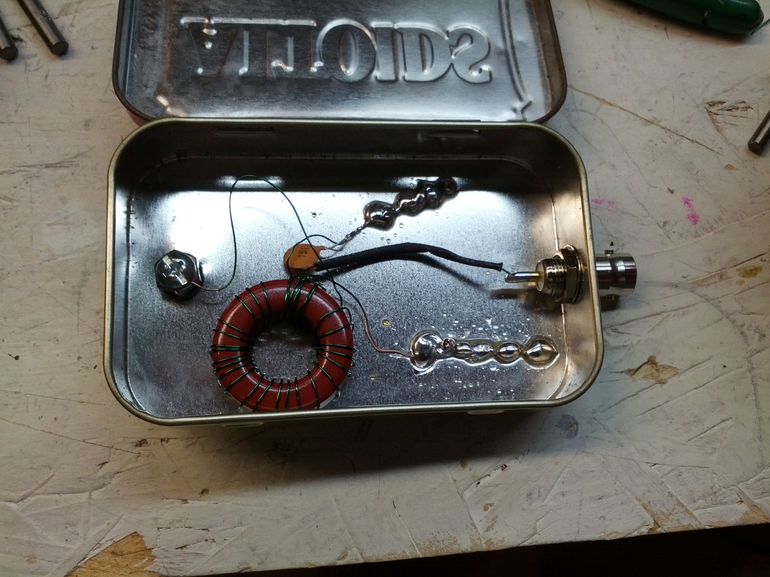
This is the inside of the box. I used an Altoids tin. The coil wire is small enough that I would consider this QRP only.
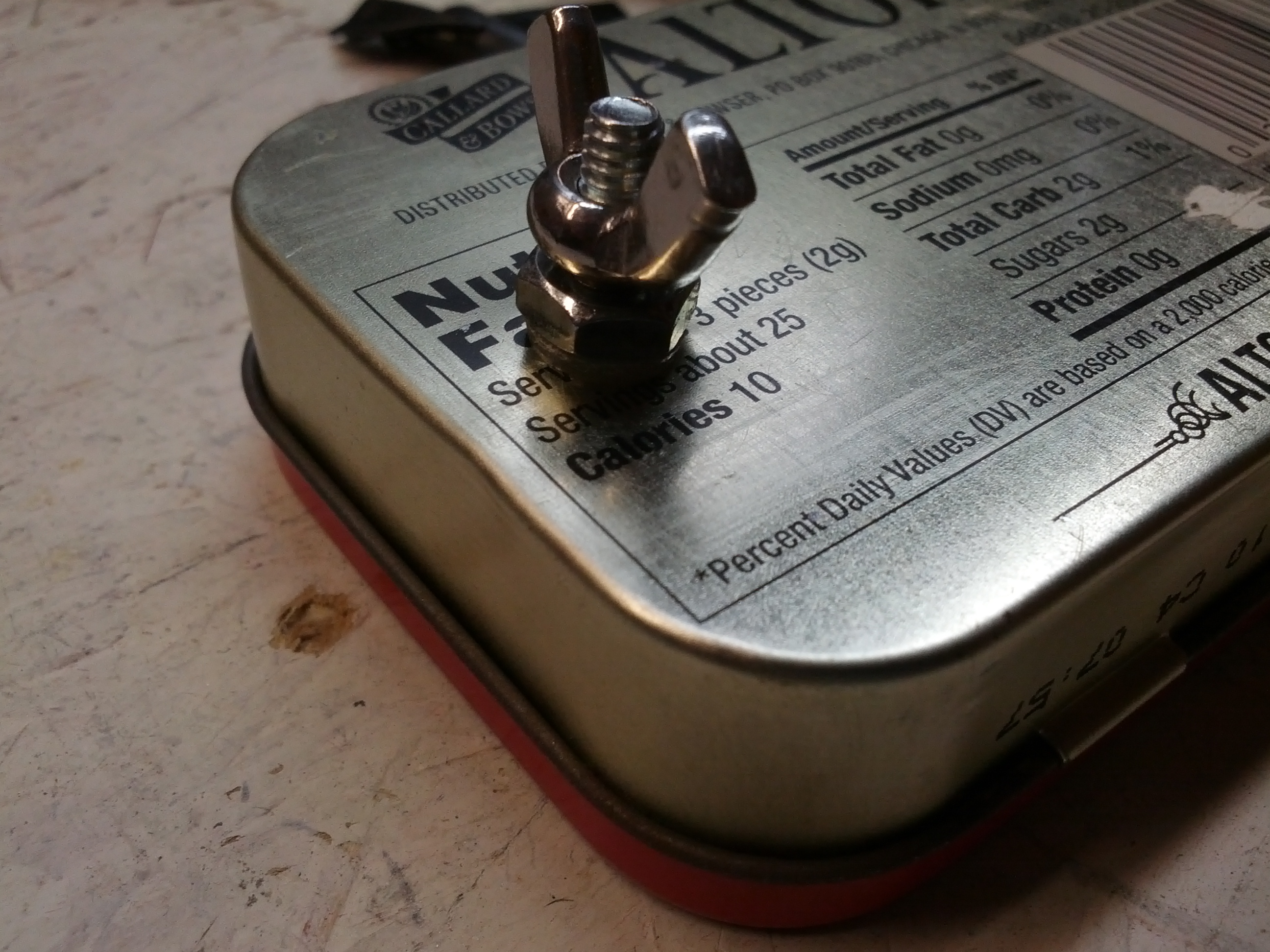
This is the back of the matchbox. It is difficult to tell in this picture, but the bolt is insulated from the case. At some point, I will improve this to have an insulated connector (right now, a good tug may cause the bolt to contact the case).
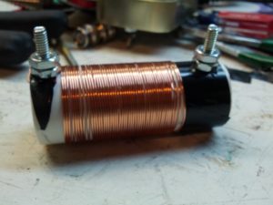
Soon to be trap. And for the love of all that is holy, DO NOT COUNT THE TURNS. It isn’t done, and I was adding turns when I should have been removing – this coil resonates on 10m, not 20m like I need.
-73-
UPDATE: W0EA connected with me via twitter to tell me I’m doing it wrong. Specifically, I should be using a ferrite core, not an iron core. Looks like I’ll be winding a new coil this weekend.
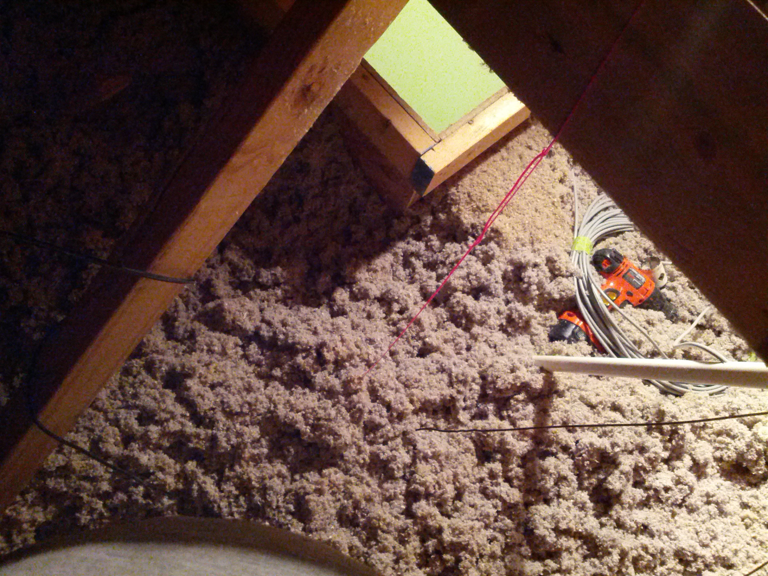
On March 30, I went into my attic to install a few antennas. I learned a few things that bear passing on. Some of these are in pictures, some are text. These are in no particular order. These assume you have cellulose insulation (the type that’s blown in).
- Be ready for a dusty environment. If you don’t wear a dust mask, be prepared to blow black snot out of your nose
- If you wear glasses, make sure they are in no danger of falling off (I almost lost mine, that would have been bad news to drop them into the insulation)
- Make sure you have extra batteries for cordless tools
- Make sure coax is supported at the top. A 20 foot run of coax can be heavy, and you don’t want the line stressed
- Make sure you have a flashlight (as well as an area lamp, like a clip-lamp)
- Take a plastic rake up there with you. Use it to move the insulation around.
A piece of mason’s line (in stylish hot pink) is great to mark where the hole is for coax.
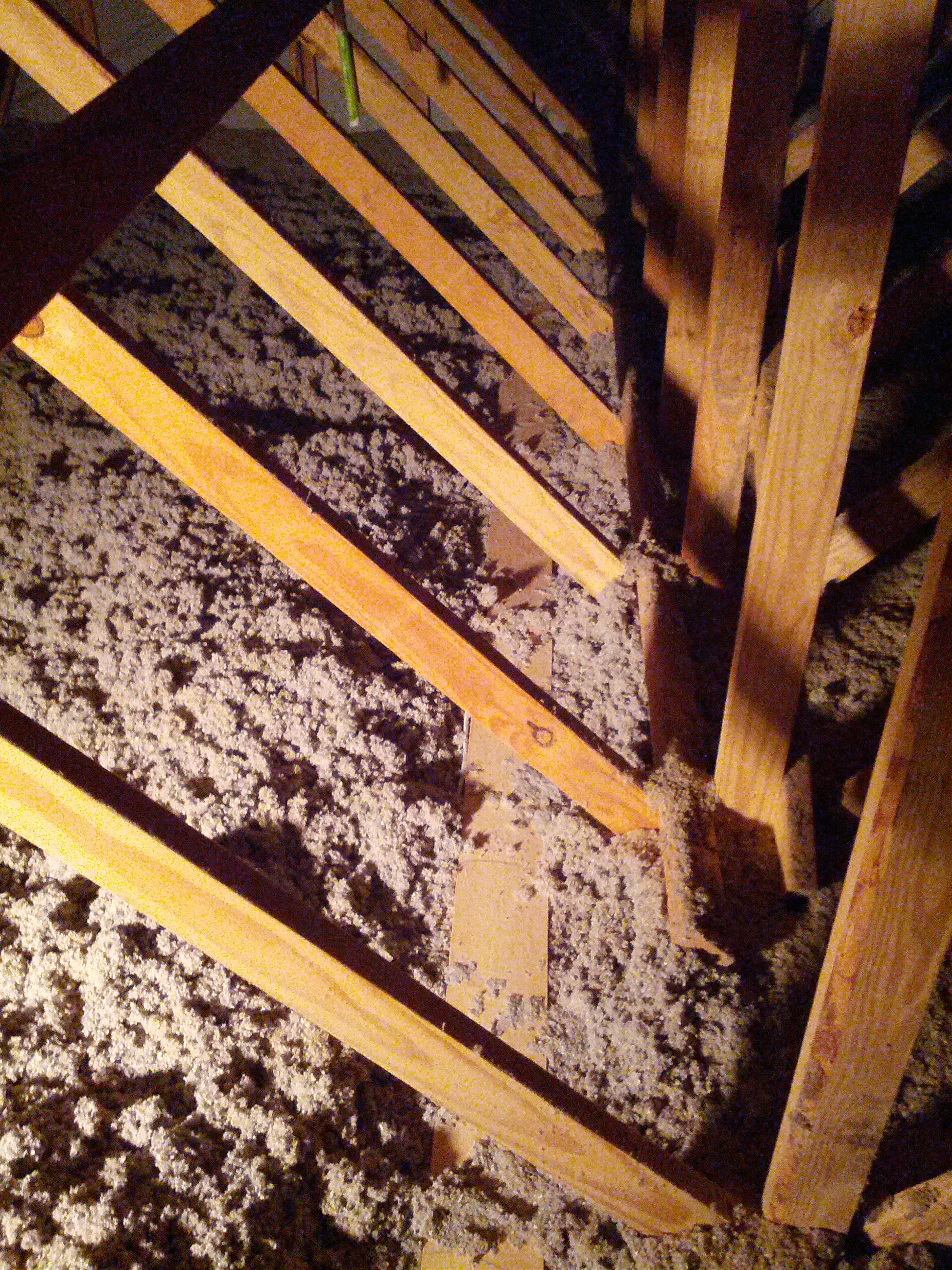
Look for things like a catwalk (like my attic has), just make sure you’re walking on wood and not PVC! Also, don’t expect the catwalk to be on both sides (in mine, it is not).
-73-
After installing my first HF attic dipole and noticing that I can hit Alaska and the Carribean really well and can’t hear New England at all, I decided I want another that is perpendicular to it (then maybe I’ll hit New England and Arizona… and Hawaii!).
I decided to do this antenna a little differently. Consider it an experiment. While I went to a lot of great lengths to put traps in my prior antenna (which shortened it’s length considerably), I decided on this one I want to try window line and see if the interference problem caused by my plasma TV is different. If not, I may be off of 40 and lower until I replace the TV with an LED TV.
Since the window line will be going down along a ventilation shaft that’s pretty large, the one concern I have is that I can’t put metal conduit in the shaft (one thing I wanted to try was to put a grounded metal conduit in the ventilation shaft and see if that fixes the interference problem).
So anyway, the pictures are below.

This is the stress reliever in the center insulator. I drilled three holes in a 3/4″ PVC coupler and used two wire ties to ensure that there isn’t too much stress on the wire joints.

This is the insulator in the center of the dipole. The long wires were soldered to the twin-lead. The PVC coupler allows for me to hang it via mason’s line.

The two sides of the dipole – wires at ~33′ each – are coiled around CLOSED coffee cans, and the window line is coiled. Everything is taped with masking tape so it can be removed easily. The cans have to be closed due the insulation in the attic – open cans would get insulation in them, closed cans do not.
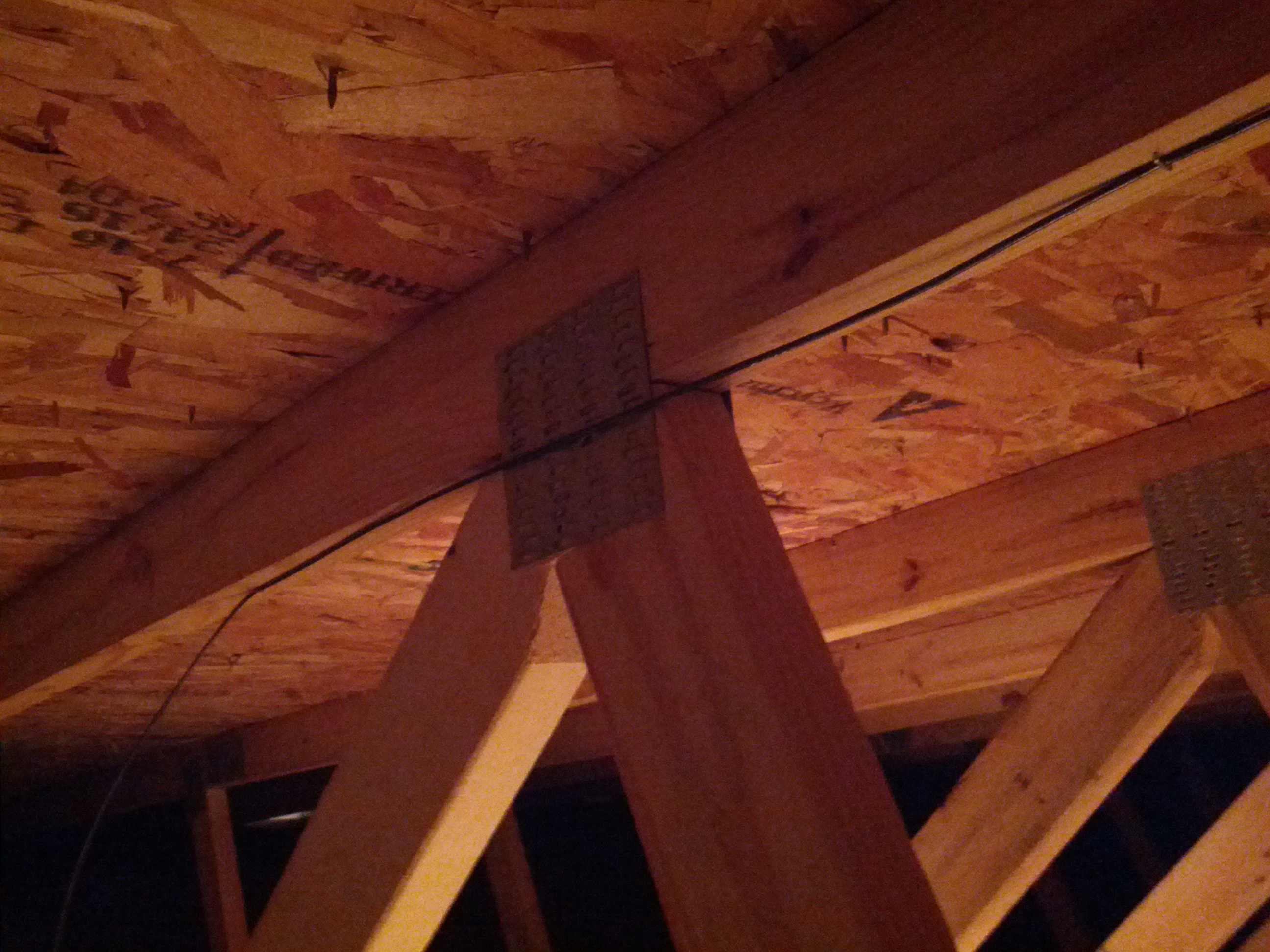
This was the only picture of the installation I could get. Let’s face it, it’s a wire in an attic, it isn’t going to be easy to see nor show anything interesting. Hope that metal plate doesn’t create a problem (there’s one on the other side too, so at least the metal plates will balance out).
I recently built a 2m groundplane antenna to be installed in my attic. Building an antenna is one thing, but getting it into the attic is another.
This is the lower mounting. Since this is in an attic, there is no need to be overly-worried about strength. There is no wind in the attic!
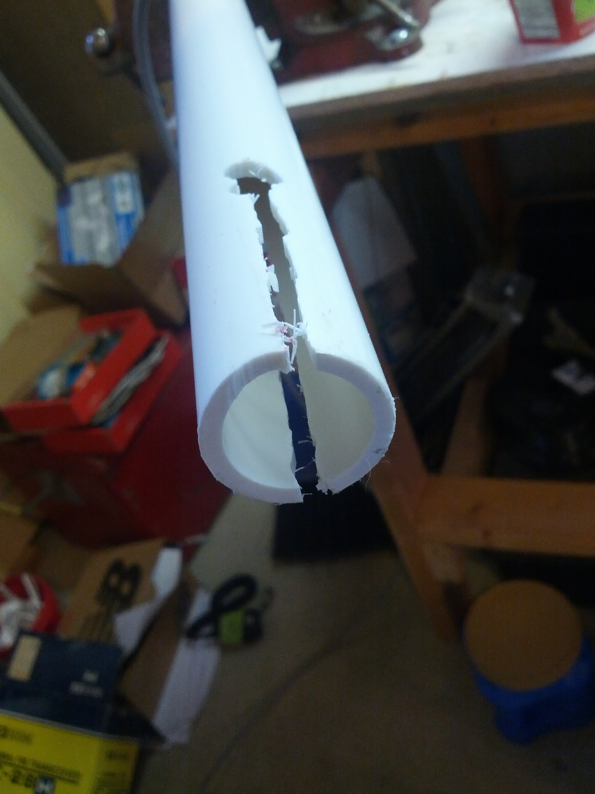
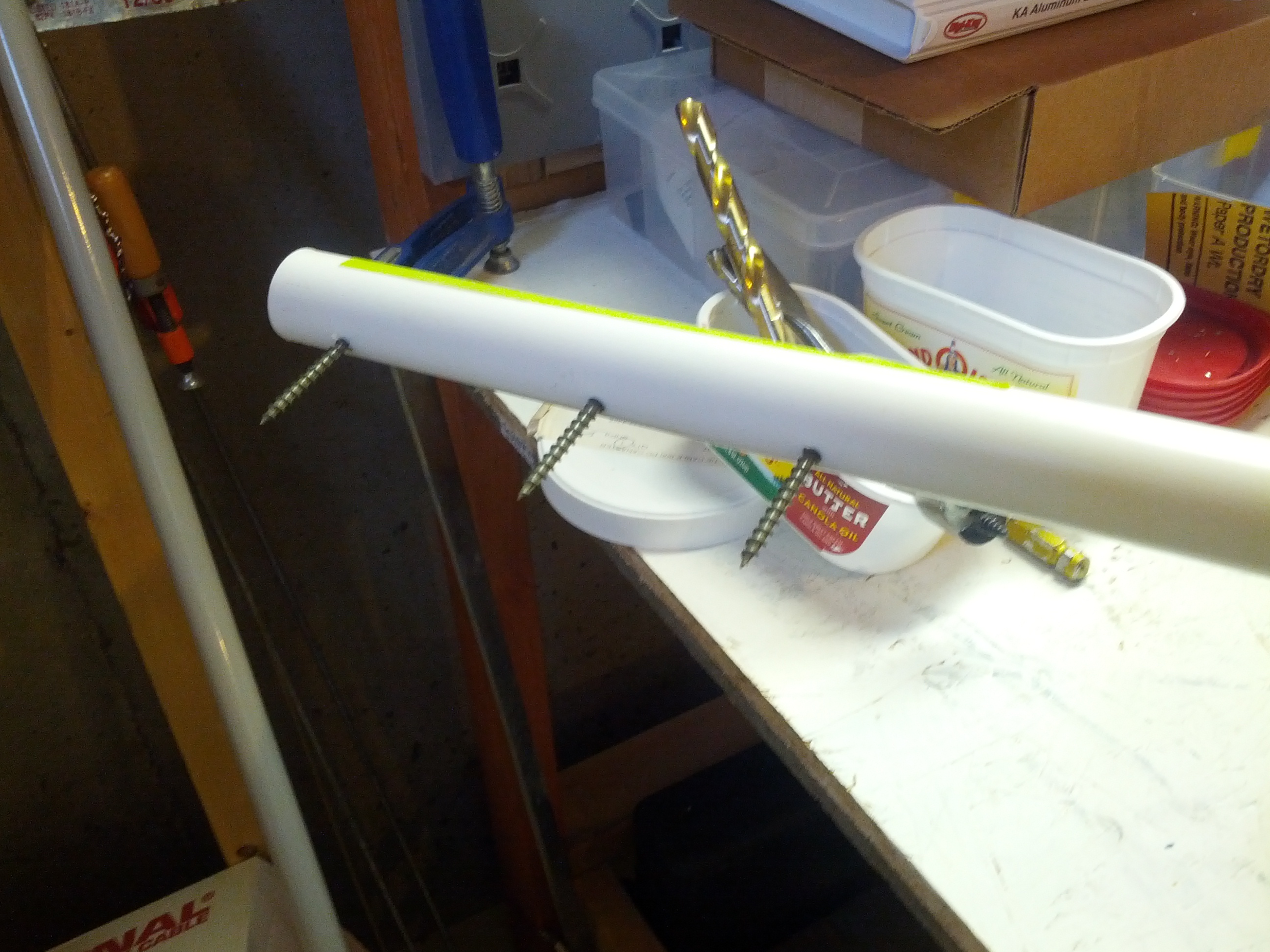
This is the slot that I used to be able to tighten the mast (which is just 3/4″ PVC) to the antenna connector.
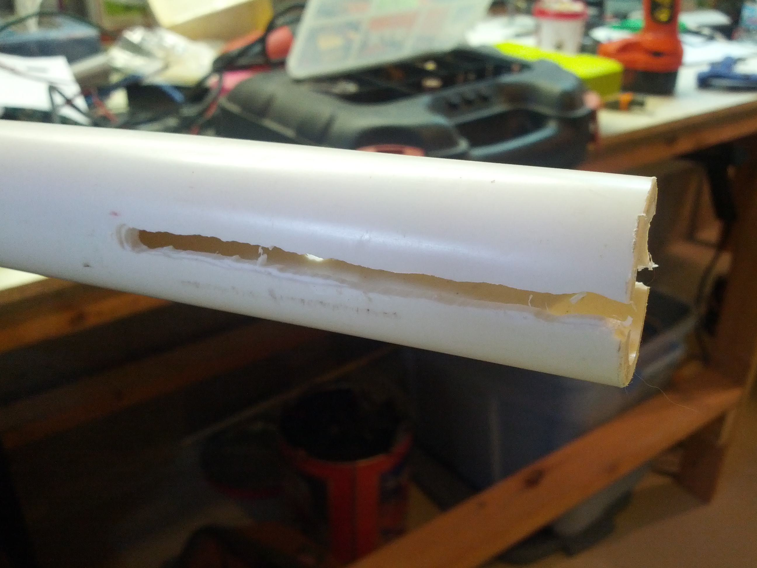
Another view of the slot in the mast. Needless to say, this was the one I did SECOND, after I got a little more comfortable with the wannabee-Dremel router attachment.
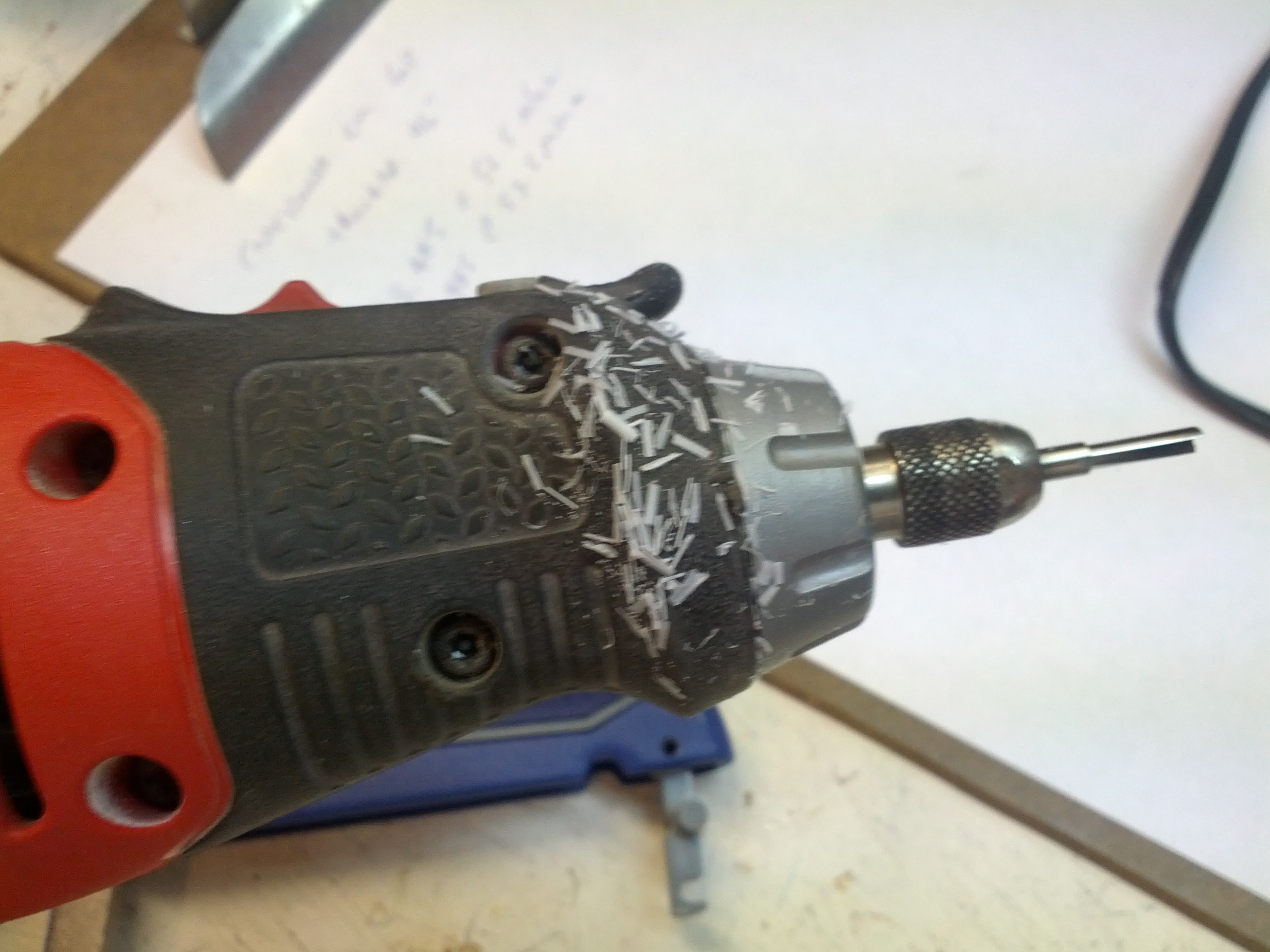
Side note, after you take a rotary tool with a router blade to a piece of PVC pipe, you will have at least a million of these little shards everywhere.
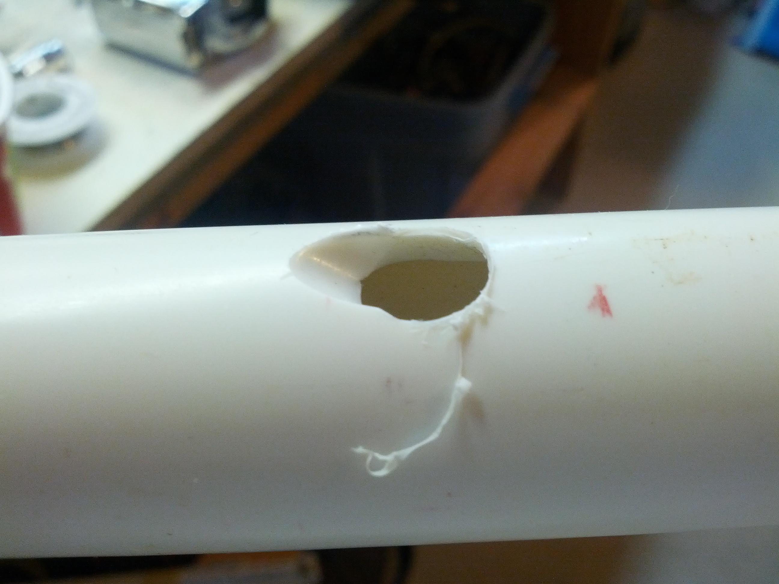
This is a detail of the coax hole. I drilled an initial 3/8″ hole, and then used a 5/16″ bit to finish the angle.
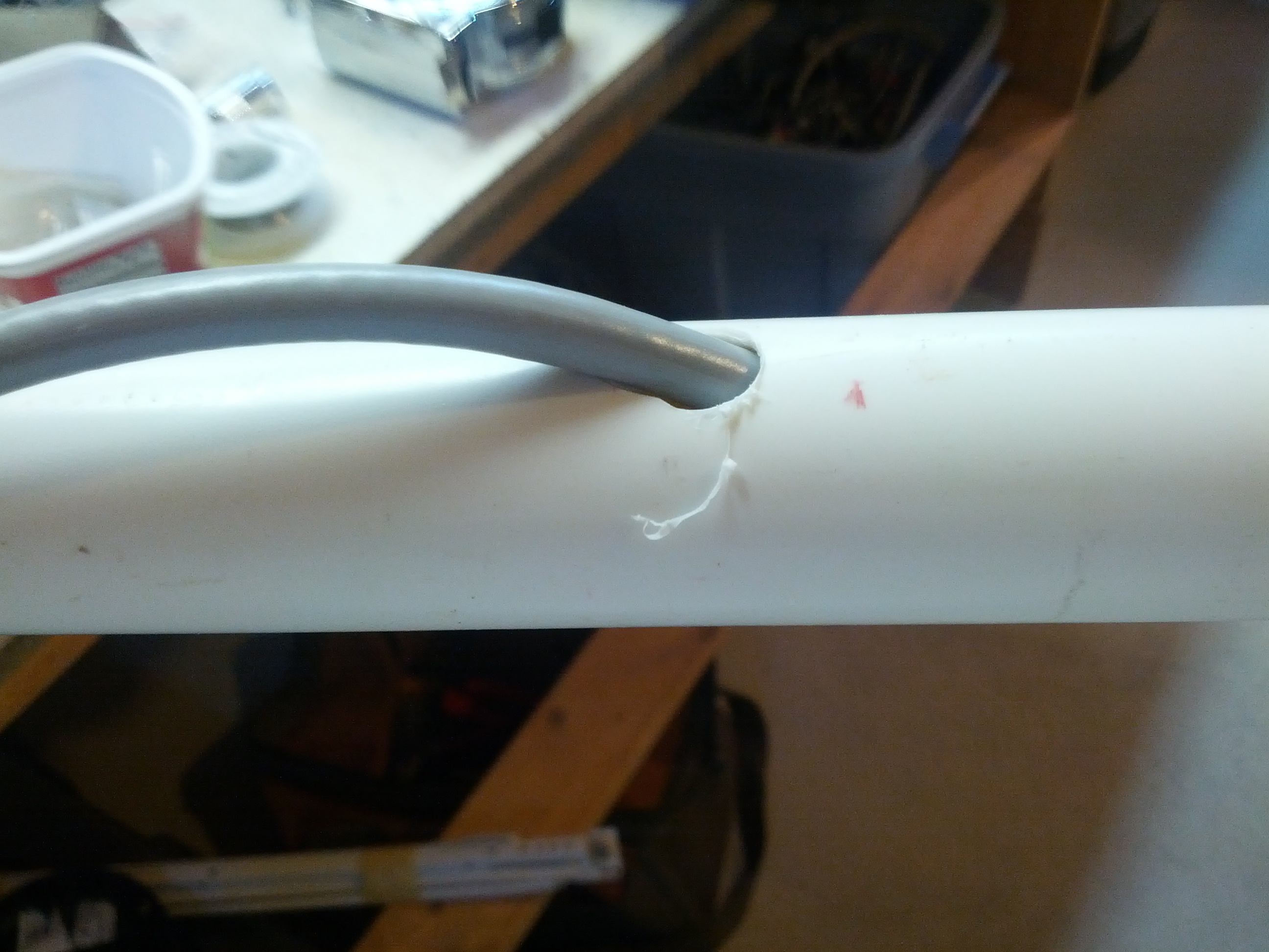
And this is the coax hole with coax going through it.
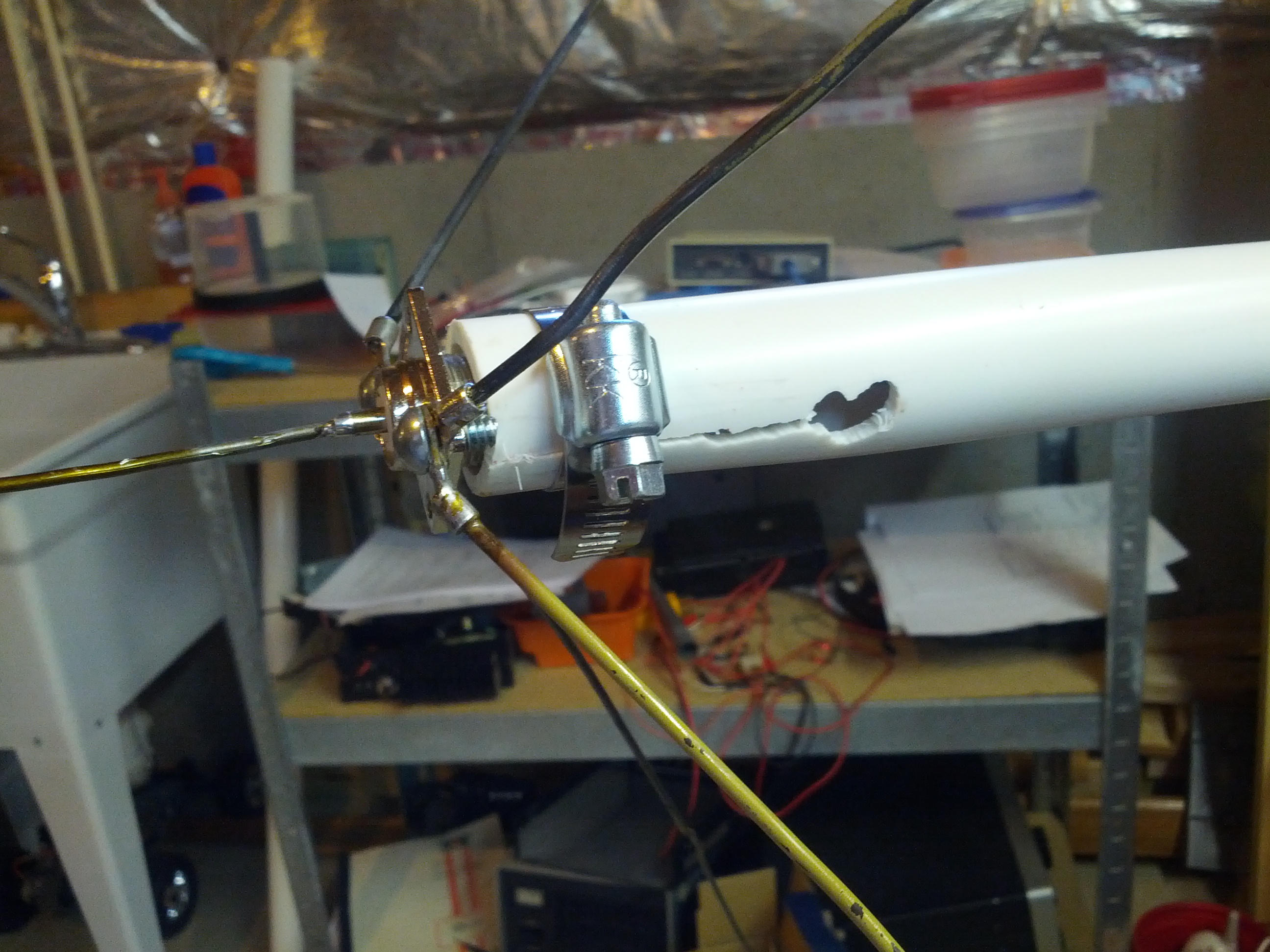
This is the finished mount. I used a hose clamp around the collar to hold the antenna mount to the PL-259 attached to the antenna’s SO-239.
As part of my attic antenna plans, I built a 2m groundplane antenna. This will ultimately be for an iGate/packet station/digipeater (maybe). I did this with some fairly simple construction out of coat hangers.
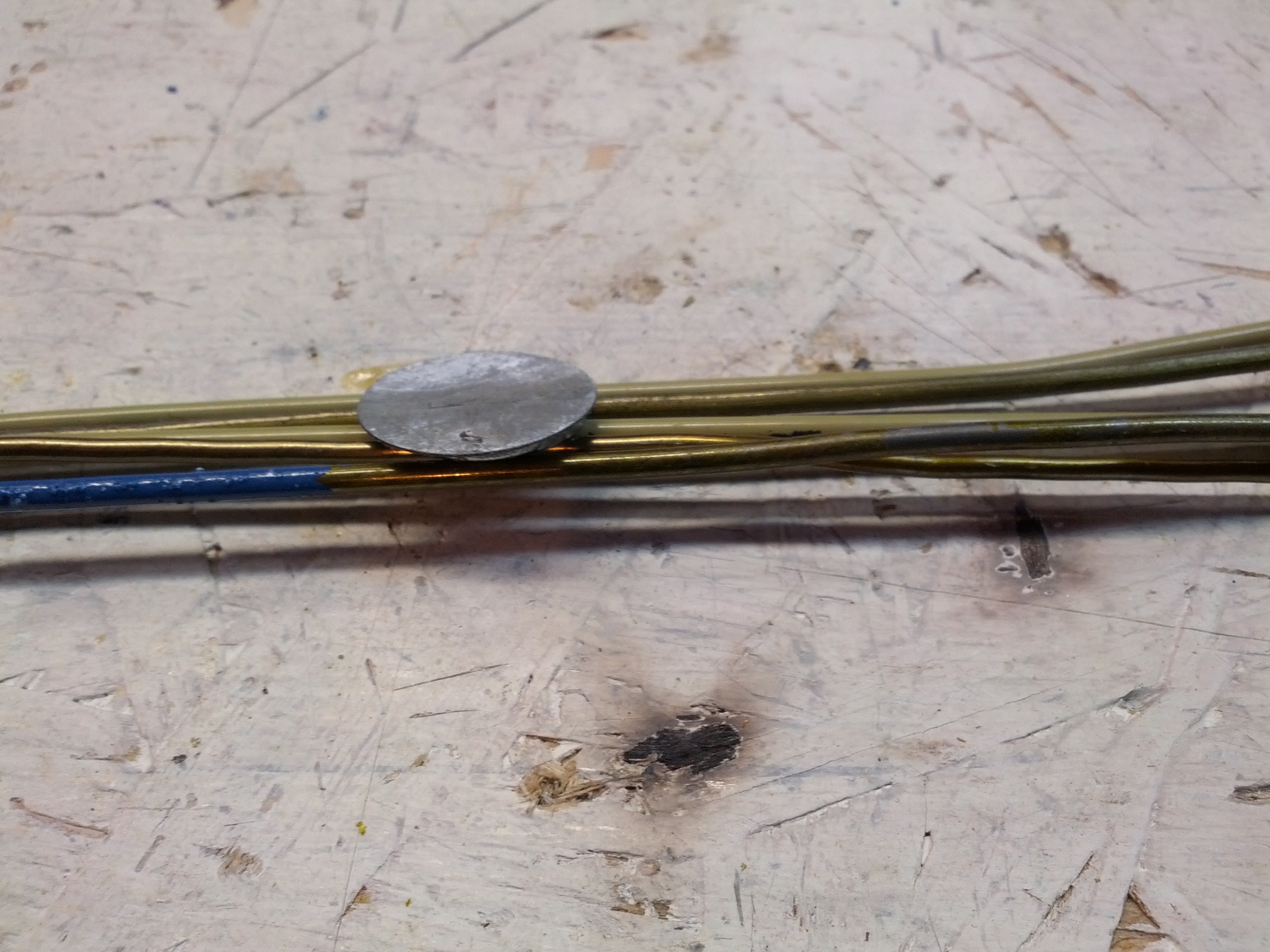
The first thing I did was make sure the hanger pieces weren’t aluminum. I don’t have any aluminum solder, and I don’t plan to get any.
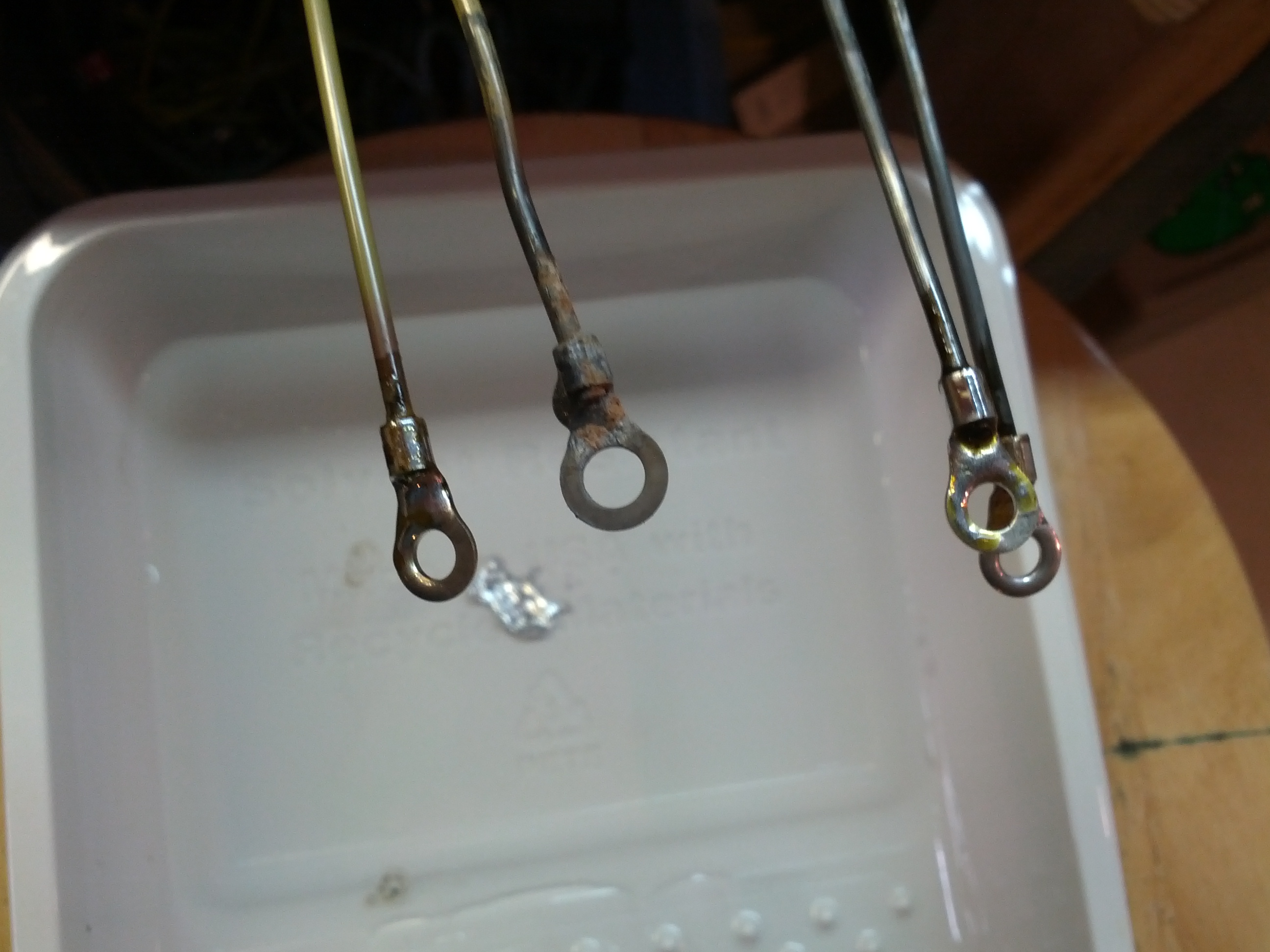
The second thing I did was solder lugs on the ends of the radials. This was, of course, after sanding the ends and brushing flux on them. This was also after taking a small blowtorch to the coating on some of the hangers.
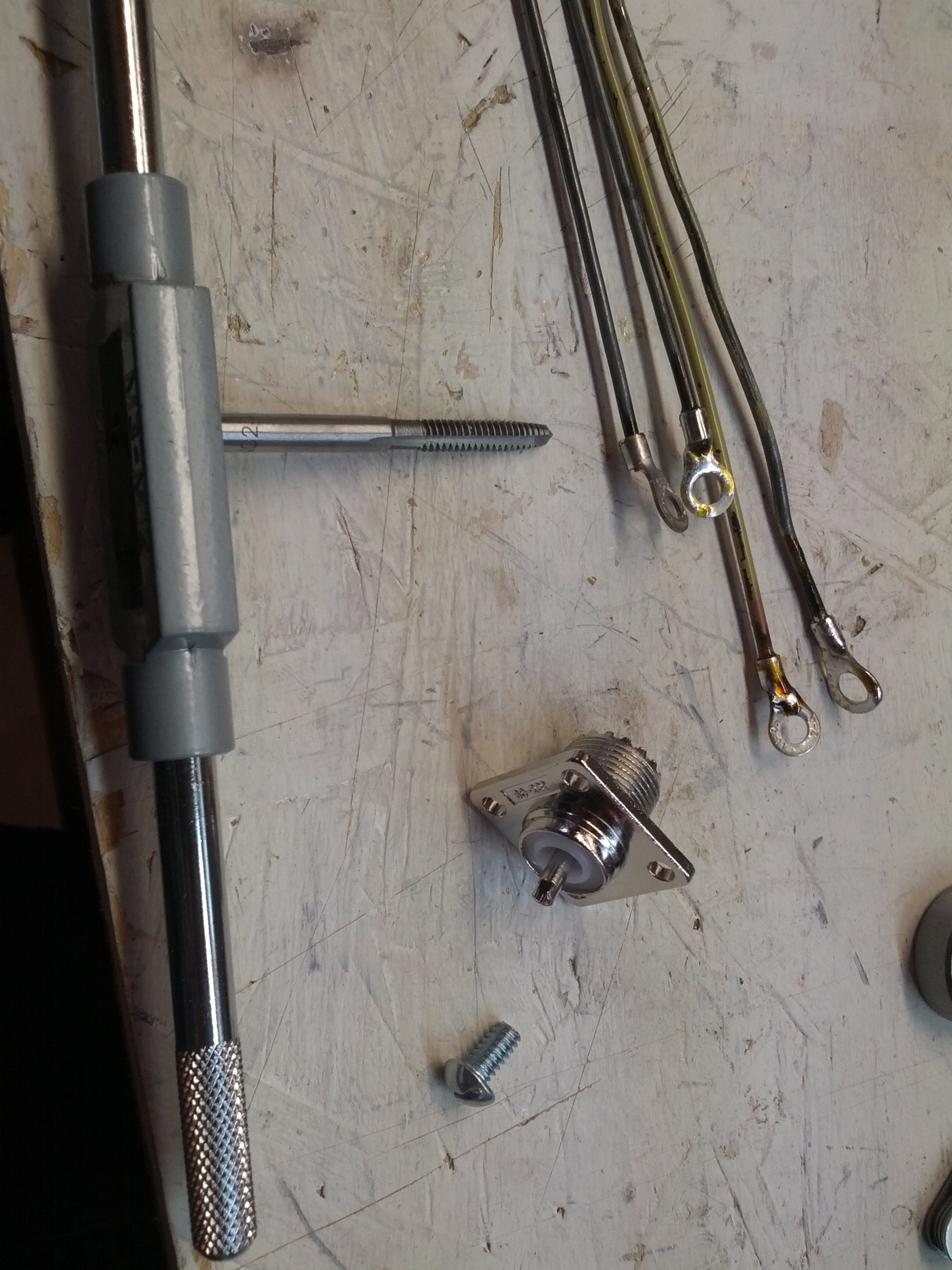
Next, I tapped the screw holes in the PL-259 chassis connector. Once I did that, I attached the radials and soldered the middle.
Taking pictures of antennas is not easy!
The SWR at the high end of the 2m band is less than 1.2:1, the low end (around 144.39) is closer to 1.5:1. Both within the acceptable limit (for my radio) of 2:1.
-73-
Winter and it’s crummy weather has been in the air here in southwest Ohio (unless there was a heatwave when this went to post, I scheduled this one in advance).
I’m doing everything wrong, but I know I’m doing everything wrong so I know what to fix.
The first thing I’m doing wrong is a magnet mount. Mine’s damaging the paint below the magnet. While my truck is 10 years old, it is damn nice for being 10 years old, and I want it to last at least another 10. So the first thing I want to do is permanently mount an antenna to the truck.
The second thing I’m doing wrong isn’t really wrong. I have an FT-1900. I like it, but it is 2m only. I really could use 2m+70cm because some of the public service events I do use a 70cm “suitcase” repeater. Being able to hit that while driving can really help make my life easier. In addition, my main repeater has a cross-link on 70cm, so being able to monitor the cross-link frequency can be pretty useful to help fix problems. Having true dual receive would be great if the Skywarn net activates and I want to listen in on it while talking on my ‘normal’ repeater. Finally, having crossband repeat may sometimes be useful.
A third thing I want to do is start running APRS in my truck. I don’t know what solution I’m going to do, but I’m not going to do something with a lot of power – I’ll probably re-purpose an old HT to do this. But when I do that, I will still want an external antenna. That will also be something I turn on and off (yeah, sometimes I want to make sure I disappear!)
A fourth thing I want to do is run a permanent line for the antenna receptacle in the back of my truck. That receptacle is for hamsticks. I may also install my HTX-100 in my truck,
-73-
I haven’t updated this in a while, not that there hasn’t been anything to update, it’s that I’ve been pretty busy.
In the past several months, I decided my trap vertical antenna in the backyard is a piece of shit. While operating in the 13 Colonies special event, I felt like I would have fared better yelling to people than using the radio. And playing some JT-65 after that made me think that the vertical is either sending everything straight up with no possible shot of reflection, or straight down in the ground. Not to mention, the guy behind me hates the thing. I think it pisses him off that he (not in my “community” can’t get the HOA to do anything about it. I haven’t been exactly secret about it’s existence, it is just that I don’t have a tower and a vertical hidden behind some trees isn’t in full view of my neighbors or the street. Well, except that guy, and he doesn’t count because he doesn’t pay into our neighborhood HOA. The HOA president has made it clear to me that the HOA will not get involved unless someone in the HOA has complained and nobody has.
My master plan was to finish a trap dipole antenna the weekend before the ARRL Sweepstakes and try to get on and at least make it half-way to a sweep. By finish, I mean that I’m going to build traps for 10, 15, 20, and 40 meters, tune the antenna, put it in the attic, and run cable down the ventilation shaft in the middle of the house.
So I learned a few things. One is that there is no way in Hell to do this without a good antenna analyzer. Another is that you should use the site that says “I constructed my traps using good quality RG-58/U coax scavenged from a discarded 10BASE-2 Ethernet cable.” should be used as guidelines. I don’t care how good quality of 10BASE-2 cable, no network administrator has used that shit since 1990!
Anyway, I found 100 feet of RG-58 to try this with (and at a damn good price). I realized almost immediately that this wasn’t going to work because damn good price is code for shit quality – the braid is aluminum. When I saw that, I immediately thought “WTF???” and tried to solder it just to make sure it wasn’t silver-colored copper or something else. Nope. Aluminum.
So I tried to make traps out of it using crimp connectors, which could have worked, but the crimp connectors don’t work too well on braid.
The following weekend was spent partially in Columbus for a meeting (on Saturday). Not being one to wake up at 4:30 AM for a long meeting, I went up on Friday and had even arranged another meeting at 2:30 in the afternoon. After that meeting, I dropped by Universal Radio and thought about buying some RG-58. Since they didn’t know if it was copper or aluminum braid, I bought RG-8X. With copper braid 🙂
Then came a weekend of winding traps. Ironically, this was on the weekend of the ARRL Sweepstakes. After having much difficulty, I found this awesome little piece of software by Tony Field, VE6YP. It is a coax trap calculator. Coax traps are a pain to make because the higher (than normal, or relative to most things a ham would build) Q. So after finding references to the capacitance per foot of “normal” RG-8X and inputting the other parameters, I found some combinations of PVC plumbing fittings and numbers of turns that would work. Of course the final traps I built, for 40 meters, were off, so I had to make a fix to those (and thank God I didn’t have to re-wind them, as I had run out of the coax I bought at Universal).
The following long weekend (Thanksgiving in the US) was spent with fixing turkey, pumpkin pie, and those 40 meter traps. I also tuned the antenna and hung it in the attic. That’s where I’m at. I tried to run the feed-line (that shitty RG-58 with the Aluminum braid, thanks to some crimp PL-259s). It’s stuck in the wall. I’m not sure how it is stuck, but I’m guessing there is a wire nest right between two sheets of OSB separated by the 2×8 flooring. Don’t ask me why there are two sheets of OSB. Normally there would be one on the top and nothing on the bottom (there’s drywall on the bottom of those same 2x8s where it’s above the living spaces, but there’s no need to have it below the floor in that area, especially with it being only a 2′ x 3′ space.
So I’m sitting here thinking “how do I get this damn wire down?” I really don’t want to pull it back and re-run it, but I may have to. I’ve been wondering if I can grab it with something, but it is 8 feet up the wall (guessing).
On the vertical, I think I’m going to leave it up for a while. It’s fuglier than sin, but since my neighbor supposedly (key word!) called the township who called the FCC a year ago but the only person to talk to me was our HOA president (the township zoning admin talked to the president and the HOA president told me all this), I’m not foolin’ with it. If they want me to do something, try talking to me. I’m not really a bad guy.
-73-
Rather than drone on about crap (literally), or new products, I figured I’d talk about what I did at the Hamvention.
My impression was just being shocked by the number of people in such a large space. The last hamfest I was at was in 2002, and there were fewer people there than at the Icom booth at Hamvention. That may be a bit of an exaggeration, but the point is made.

I originally wanted to hit four forums. I actually hit two: propagation and techniques of the best operators. They were interesting. I got there too late for 10 reasons to QRP (I already had the most important reason, and that was because I can’t afford something better!). I decided not to stay in the room for kitbuilding.
Most of my day was spent looking around the flea market. I really wanted to bring home an HF rig. After an hour or two of looking, I saw a lot of prices outside my price range, and then saw a table with a stack of two Radio Shack 10m rigs. $45 for both, one works one for parts. I couldn’t resist.

Not the ones I bought, but the same model
With the two rigs stuffed in my backpack, I called my wife and asked her to do some research for me. I need a power supply, since I have no intention of operating HF mobile (and I don’t think my truck can power an additional rig). She looked up the power specs and I set out in search of lunch and a power supply.

…well, power supply now, lunch later. Those are some long lunch lines.
So, I made my way around the rest of the flea market, finding a power supply for $30. Into the backpack. Those things are HEAVY.
By this time, I did stop for lunch and got into a conversation with a ham from Syracuse (I think) and originally from Minnesota. He told me about his antenna – a dipole attached to his deck eaves, something I will likely imitate once I build a deck.
Upon more looking around (and some of this, I don’t know when I saw it), I did see a cool quad antenna made with PVC (another design I will likely imitate, since I need a decent antenna for 10m now).

I also walked off with a hamstick for 10m and a handful of connectors and antenna insulators.
When I got home, I began testing things, and even though I was in less than perfect testing conditions (if you saw the wire I was using for power, you’d understand that less than perfect part). One of the rigs worked fine. The other turns on but has no display. I haven’t diagnosed it, but when I get around to it, I plan on checking it against the known mods for the HTX-100, since the speaker lines were desoldered (not cut or ripped).
So now I have the Milford Hamfest to look forward to next month.