
Tag Archives: Arduino
I’ve been reading a lot about receivers, and it sounds like one important thing is filtering. It makes sense too – simple receivers can suffer from front end overload due to a strong signal. And when on the ham bands, you never know where that strong signal may be – it could be someone driving down the road (which is a bit obvious once you see it), but in my neighborhood, if you don’t know me, you’re probably not going to know about the antennas in my attic.
I don’t have a spectrum analyzer, and since I’m a traffic engineer, I really don’t have access to one. I don’t need a full-blown spectrum analyzer, either, I just need to sweep through the HF band and get the difference between signal input and output. Math will take care of the rest.
$$dB=20*\log{\frac{V_{out}}{V_{in}}$$
The way I figure it is this:
An Arduino (and this could become a Raspberry Pi or any number of other devices, but I’m going to use an Arduino because it’s cheap and relatively durable) controls a direct digital synthesizer (DDS) module that just scans through it’s limits… well, probably something like 0.5 MHz – 40 MHz – that gets me into the AM broadcast band (which can be a source of strong signals) to above the 10m band (I don’t know what’s up there, but whatever’s there is probably not running 50,000 watts).
The output of the DDS would have an RF voltmeter and a probe to go to a filter. There would be another RF voltmeter to sense a filter output. The Arduino would handle not only control, of the DDS, but also sensing the voltage.
It’ll look something like this:
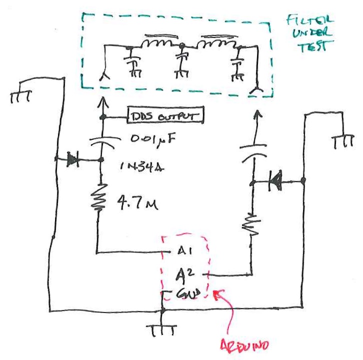
This is a block diagram/schematic of how this will work. I didn’t include the DDS module, which would be tied in there somewhere.
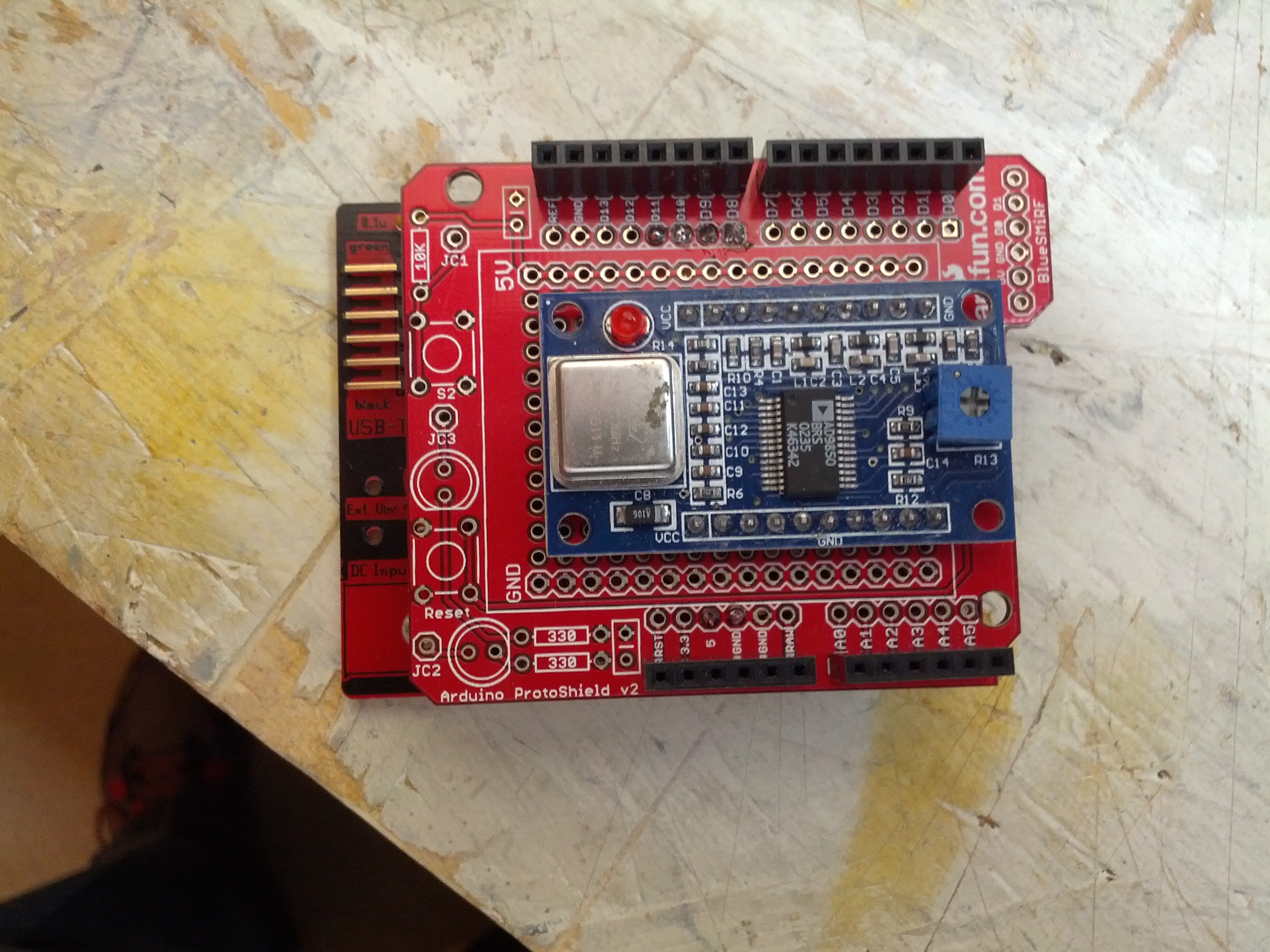
The Arduino and DDS will look like this:
There will have to be a companion app to this. In Java (not just because I’m drinking coffee, but also because it’s cross-platform). It’ll look like this:
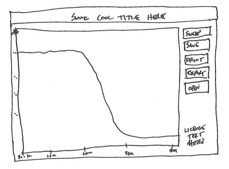
This is likely how things would look. Simple. A button that tells the Arduino to sweep, and some other important buttons.
I have the perfect item to test with also. One thing I built and don’t use (and never truly finished) was my Softrock RXTX. I need to build a filter for the output to keep the harmonic of the 7 Mhz fundamental from being too strong on the 20 meter band. I wound the coils while watching the Super Bowl-over-the-Broncos and printed a circuit board just before the game started.
Easy and small, but for 0.95 Watts, you don’t really need much.
I’m not really sure if this will work, but it certainly seems like it would, and I think it would be interesting to see how some filters respond on this compared to a real spectrum analyzer.
-73-
The bus pirate Arduino shield is a discontinued item from Dangerous Prototypes. I picked up the PCB via a free PCB coupon a while back, built it a few months later, and then finally decided to use it because I think I have something to use it with. Note the key word – think. This is what happens when a traffic engineer plays with electronics.
The shield was not easy to get started with, mostly because I had to look (and look, and look) for source. I finally found it on Toby Jaffey’s Github Page. Once I loaded it, I found that connecting with Tera Term (and likely any terminal emulator) on that COM port using 19200 baud 8N1 no flow control worked and I was able to play around doing things like:
>led 1 (turns the mode LED on)
>led 3 (turns the mode LED to a fast blink)
led appears to be 0-6, with 0=off, 6=on, and 1-5 are blink rates, slow to fast.
help and version are pretty self-explanatory.
Stay tuned for more, but in the meantime, here’s a picture of the setup.

The Bus Pirate Arduino Shield is the shield sitting on top of the Arduino in the background. The item in front is the Bus Pirate Demo Board that I’m using to test the shield. There are a few joints that I missed soldering and there are a few missing capacitors.
There’s going to be a lot more to post as I start into this. Incidentally, this is to assist with the Android App.
-73-
This is Part 2 of God-Only-Knows How Many. Part 1 is here.
A little progress. My weekend was busy with website design for another site I run, the CQWW contest (I spent only around 45 minutes, only 20 QSOs between interruptions of keeping an eye on my kids and some minor radio difficulties), yard work, and taking a cat to a emergency care center (she’ll be fine, but my finances will not be).
Arduino Code: Minor Fixable Frustrations
The Arduino code is in the repository. I’m not going to copy it here, since it is still not working correctly. Over the past week, I’ve tried three different libraries and I think I’ve settled on using adk.h from http://www.circuitsathome.com/ (you can get it from here). What I DO have is an Arduino that once plugged into my Nexus 7, it will tell the Nexus to open the correct app. That’s pretty darn cool. What I do not have (yet) is the intelligence built into the program to initialize the USB and send data. Possibly related to this, it seems like the Arduino only wants to send data when it has a serial connection open (from the Serial Monitor in the Arduino Dev Kit). I have more work to do.
Android Code: Logging, Logging, and More Logging
I have been writing and rewriting the code trying to get something pop into aLogcat or on the app screen with little luck. I have many lines with Log.d and Log.v to see what is going on. The best I’ve had is a “Data recieved” message*. I have more to do here. And as I indicated above, I ONLY see that message if I open the Serial Monitor.
* = The misspelling was intentional. I can’t seem to spell ‘receive’ correctly to save my life, and there is no spell check in Eclipse.
Stay tuned for next week’s episode.
-73-
This is Part 1 of God-Only-Knows How Many.
I finally got around to working on the easy button – I found a decent (not great, just decent) tutorial on the web that discusses sending the status of a button attached to an Arduino to an Android device. I’ve been making changes and learning about bitmasks and bit shifting (something they never teach traffic engineers!).
The initial (key word!) Arduino and Android code is written and up on Github. Right now, I am writing a test routine that will eventually morph into a functional program. I’ve really only spent time on the Arduino
I took the code from the tutorial link above and made quite a few changes.
Before being able to compile the code, you need the microbridge Arduino headers. Then, you have to fix some of the source files – in usb.cpp, max3421.h, and Adb.h, there is an #include “wiring.h” which needs to be changed to “wiring_private.h”. Once you’ve installed the library (copy the files to the Arduino libraries folder in it’s own folder), the following should (key word!) compile and send a binary output string to the serial monitor based on the buttons that are pressed.
The binary strings on the screen represent the buttons that are pressed in the arrangement of 1abc1 where a is 1 if button 1 (pin 4) is pressed, and 0 if it is not, b is button 2 (pin 5), and c is button 3 (pin 6). So…
10001 = no buttons pressed
11001 = button 1 pressed (pin 4 high)
10101 = button 2 pressed (pin 5 high)
10011 = button 3 pressed (pin 6 high)
11101 = buttons 1 & 2 pressed
11011 = buttons 1 & 3 pressed
10111 = buttons 2 & 3 pressed
11111 = buttons 1, 2, & 3 pressed
IN THEORY, this will all be sent to the Android device and the Android will display what buttons are pressed on the screen. I have that designed, but I haven’t tested it and my Android code won’t compile yet. With luck, that’ll be next week’s blog post.
REVISION: Note the fact that the preceding paragraph says “IN THEORY” in all caps. That means that it really doesn’t work at all so don’t use my code… yet. 🙂
On the todo list for this is using interrupts to listen for the button as opposed to listening for a change every 100 milliseconds.
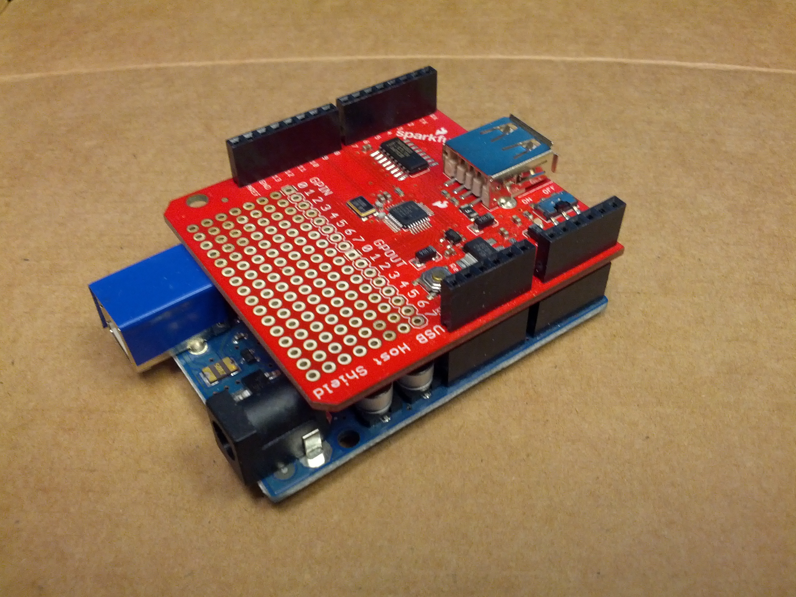
This is – so far – the development device. An Arduino Uno and a USB Host Shield from Sparkfun.
-73-
For anyone that’s been following me on Twitter, you’ve undoubtedly seen my tweets about getting some DX on 10m while mobile. For whatever reason, 10m seems to be the sweet spot with my 706 and the hamstick.
The Setup
The current setup is here (old pic)

This is the radio in the lower center console of my truck.
The Issues
One issue with this is that it is difficult to control the radio. Part of it is that I need to use it more. Part of it is that it is just over an arm’s length away. Solution: I have the head separation kit, I need to mount the radio somewhere easier to see and control.
The only other issue is logging. I’ve tried using Google Keep and Evernote, but they haven’t worked very well. Keep tries to transcribe the speech, which it usually does poorly with callsigns and frequencies. It will normally get the ubiquitous “five nine”, though. I’ve decided I need an “easy button”.
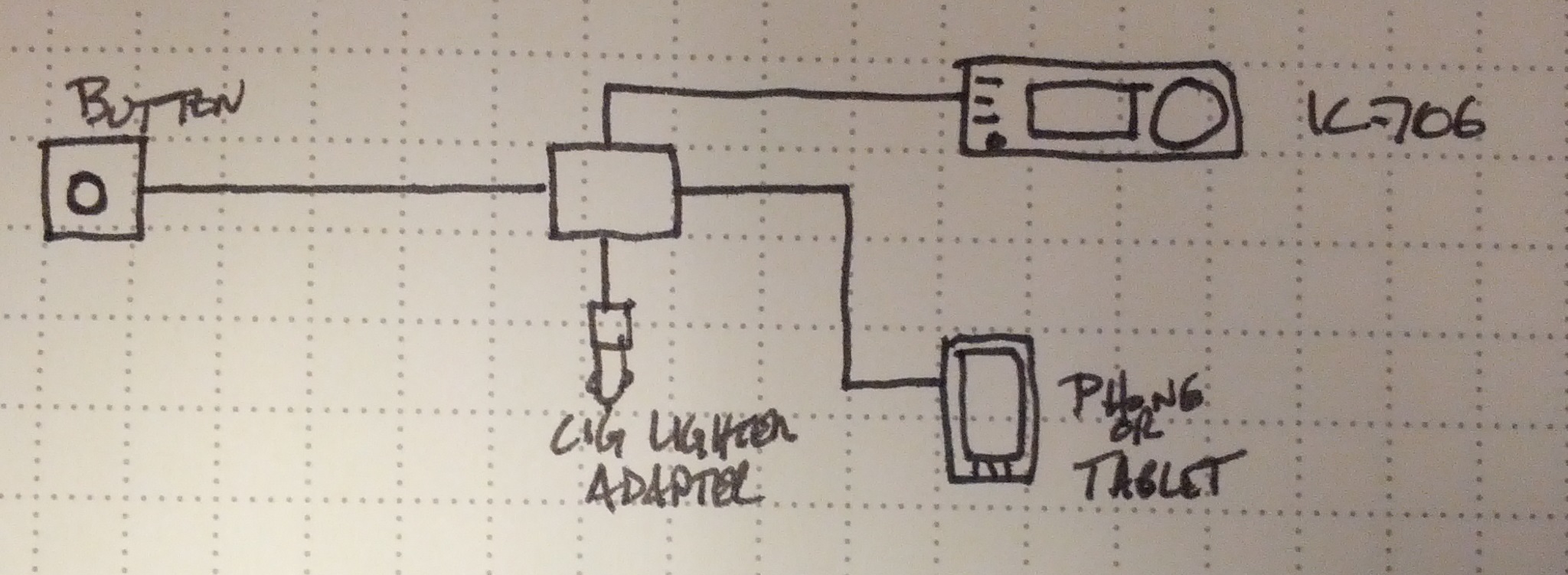
Easy button block diagram
So, an Easy Button. Ultimately, this will become an Android App. It’ll probably be Arduino powered. It’ll likely be open source, too.
I figure when it is plugged in, it should start an app (maybe I’ll have to do this manually). It’ll charge the Android device (hence the cigarette lighter adapter). It may run the GPS to get location when the button is pressed (I can think of a few uses for that); it would definitely get the time and date (UTC, of course!) from the phone, and it would prompt the phone to record the callsign, signal reports, and any other notes. It would also connect to my IC-706 to get the frequency and mode.
Stay tuned!
-73-
One of the things I am doing for Halloween involves a pumpkin, a proximity sensor, and a music shield. Unsuspecting suspect comes near pumpkin, and the pumpkin talks to them. This is a very simple item, but one that can be pretty fun and very useful.
The Arduino is below. This is based on an Uno and uses a music shield and a proximity sensor. The music shield is from Seeed Studio and is the most expensive part (save the Arduino itself). The proximity sensor is a Sharp sensor, which can be bought from several sources. One potential addition may be a small op amp as an audio amplifier.
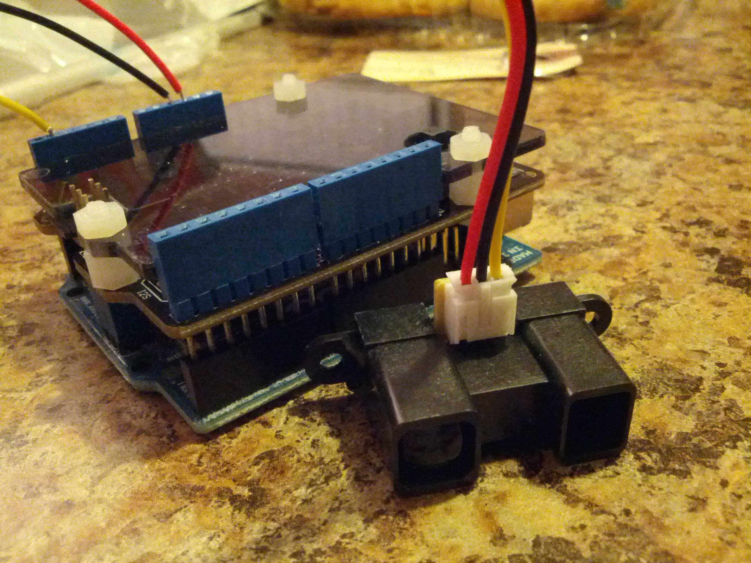
This is an Arduino Uno with a music shield and a proximity sensor.
The code is on Github.
-73-
I gave a presentation to the Oh-Ky-In Amateur Radio Society on August 6, 2013. This was an update of the presentation I gave to the Cincinnati FM Club in February, which was an update of the presentation I gave to the Milford Amateur Radio Club a while back. This page is a set of links for those that attended or missed the presentation.
Presentation: Introduction_to_Arduino_Microcontrollers (PDF warning)
Links Mentioned:
QRPTracker (satellite tracker)
Starter Sets:
Sparkfun: New Starter Set (with Arduino Clone, $50), New Inventor’s Kit ($100), Starter kit ($60)
Adafruit: Starter Pack ($65), Starter Kit ($125)
(added 2013-08-22) Seeed Studio: Starter Set ($70), Starter Kit (bigger) ($120)
Add-On Packs:
Have an Arduino board but not enough accessories or don’t know where to get started? Seeed Studio has a “Sidekick Basic Kit” that can get you up and running – it doesn’t have an Arduino, but it has a lot of components (etc) to get you started. And it’s $20. Seeed Sidekick Basic Kit ($20)
NOTE: Look hard at what these packs include! There ARE differences.
Raspberry Pis and Beagleboard Blacks can be bought at Mouser, Digikey, and Newark Electronics/Element 14. Raspberry Pi accessories (like the Pi Plate an Pi Cobbler) can be bought at Adafruit or Newark Electronics/Element 14.
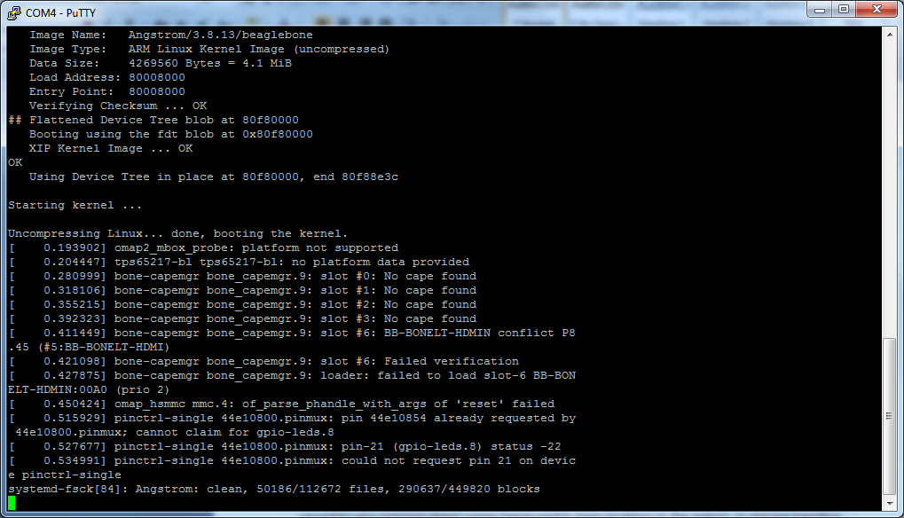
I’ve been playing around with my BeagleBone Black quite a bit recently. It all started with one of my coworkers bringing in a rain gauge that we had collecting dust somewhere in an office storage room. I had been installing software to the BBB and ran out of space on the eMMC (internal memory) chip. So I tried to boot from an SD Card – the one I updated the BBB to the latest software with and still loaded with the image. It appeared to me that it maybe had been reloading the eMMC, but I couldn’t tell for sure. After around a half hour, I power-cycled the BBB. Bad news, it wouldn’t boot. I don’t have the correct HDMI cable, and I’m at work, so my resources are pretty limited.
Enter the FTDI port on the BBB. Enter the fact that I don’t have an FTDI cable at the office. D’oh!
But I have a few Arduino Unos.
I wondered, and then quickly looked on the Internet to find a page on Instructables that describes how to use an Arduino as an FTDI programmer. I then looked at a reference for the pinouts. A page at Circuitco has the pinouts that seemed like they’d work – ground, RX, and TX. I hooked them up and…
It gets a little bit more MacGyver-ish. I have only a small box of jumper wires at the office, a few shield headers, and a breadboard…
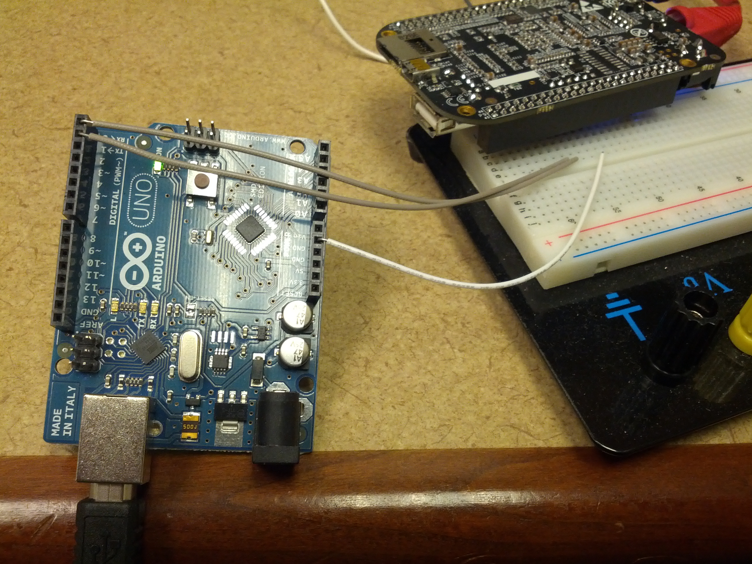
This is an overview of the setup. The Arduino RX, TX, and Ground are connected to a breadboard that has a shield header that connects to the BBB’s FTDI port.
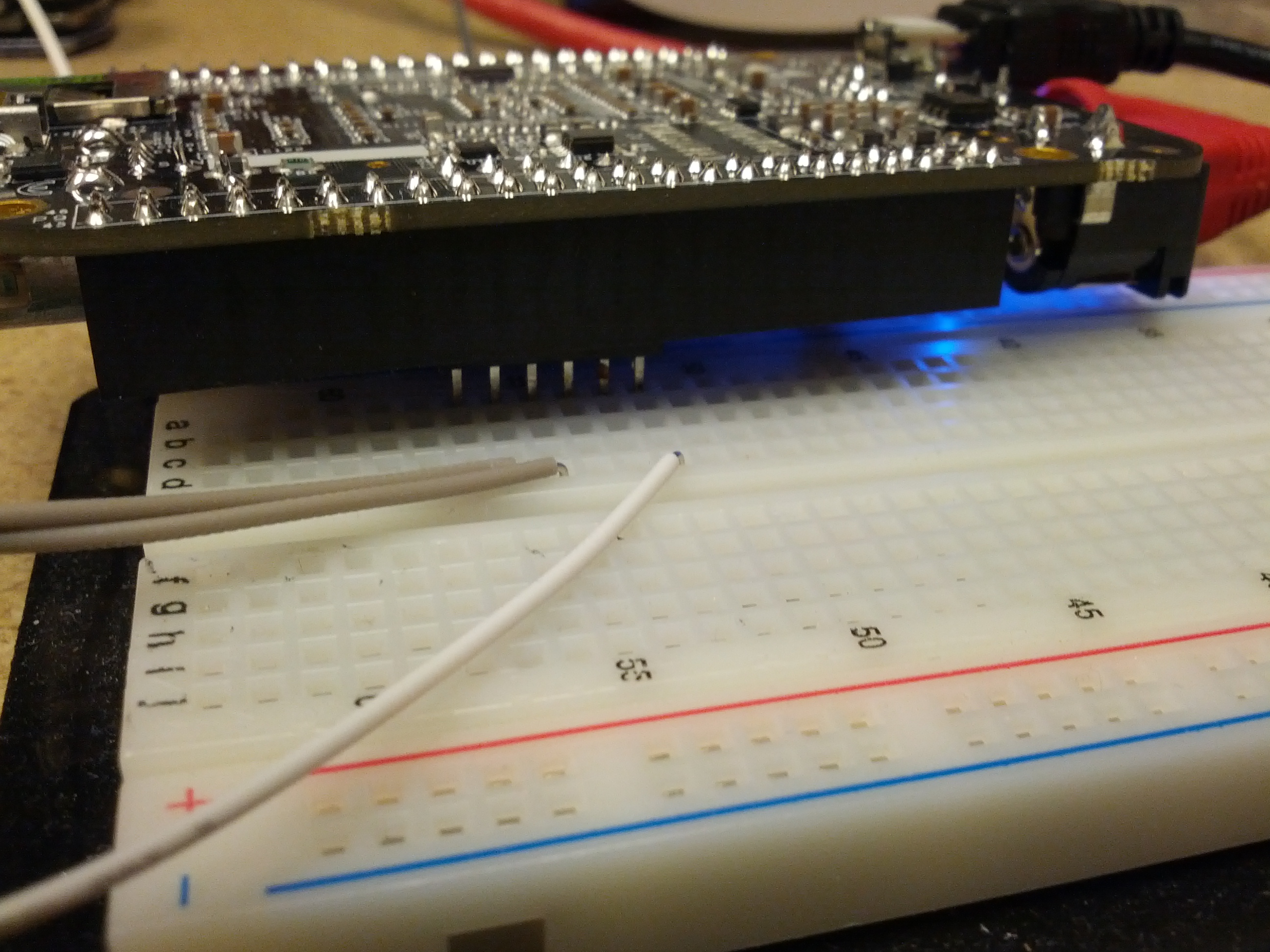
This is the connection between the breadboard and the BBB.
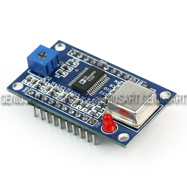
After reading a few blog posts out there from others, I decided that it would be interesting for me to get hold of an AD9851 module. My initial plan is to build an antenna analyzer and something else (I bought two).
The major engine of these modules is an AD9850 Direct Digital Synthesizer. This chip can be purchased in quantity for $15.25 EACH from Newark. From Digi-key, $15.37.
The two modules I purchased on eBay were $8.90. Total. With shipping.
And these modules aren’t just the chip…
So I don’t totally understand how this eBay seller makes money, but it appears he does (it appears he’s/she’s sold quite a few of them, based on their eBay feedback rating). What I do (now) understand is why we no longer do electronics manufacturing in the USA.
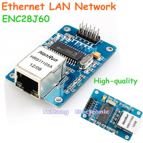
After ordering this (at the time of writing, I’m still waiting on shipping), I started looking in to adding Ethernet capabilities to one of my Arduinos. So I looked in to the ENC28J60-based chipsets. After finding one for £22.90 and one for $35 on Sparkfun, I looked on eBay. $4.09 each from Hong Kong. $2 for shipping. At least this isn’t as egregious as the AD9850 modules, as the ENC28J60 chip is $2.36 in quantity from Digi-Key.
I can’t imagine this is news to anyone in the electronics industry, but I’m just an amateur radio operator and traffic engineer. I found this interesting. And I’m not complaining, as long as this stuff I get from China works! 🙂
Of course, there is a drawback to this – the wait. I got a confirmation of shipment for the DDS modules on March 26, 2013, and they arrived on April 6, 2013. I ordered the Ethernet modules on April 5, 2013, and they have yet to arrive. So there is a delay, but with some planning, a hobbyist like me can deal with it.
-73-
—UPDATE—
The Soldersmoke Daily News blog has another possible reason: a design flaw. See his post for details.
I gave a presentation to the Cincinnati FM Club on February 6, 2013. This was an update of the presentation I gave to the Milford Amateur Radio Club a while back. This page is a set of links for those that attended or missed the presentation.
Presentation: Introduction to Arduino Microcontrollers
Links Mentioned:
QRPTracker (satellite tracker)
Starter Sets:
Sparkfun: Starter kit ($60), Inventor’s Kit ($95, $100)
Adafruit: Starter Pack ($65), Starter Kit ($125)
NOTE: Look hard at what these packs include! There ARE differences.