
Tag Archives: DDS
A while back, I bought a few DDS modules through eBay. I used code from NR8O to program one of them and started pulling parts from the bin and pushing the output signal through the parts and into a load resistor.
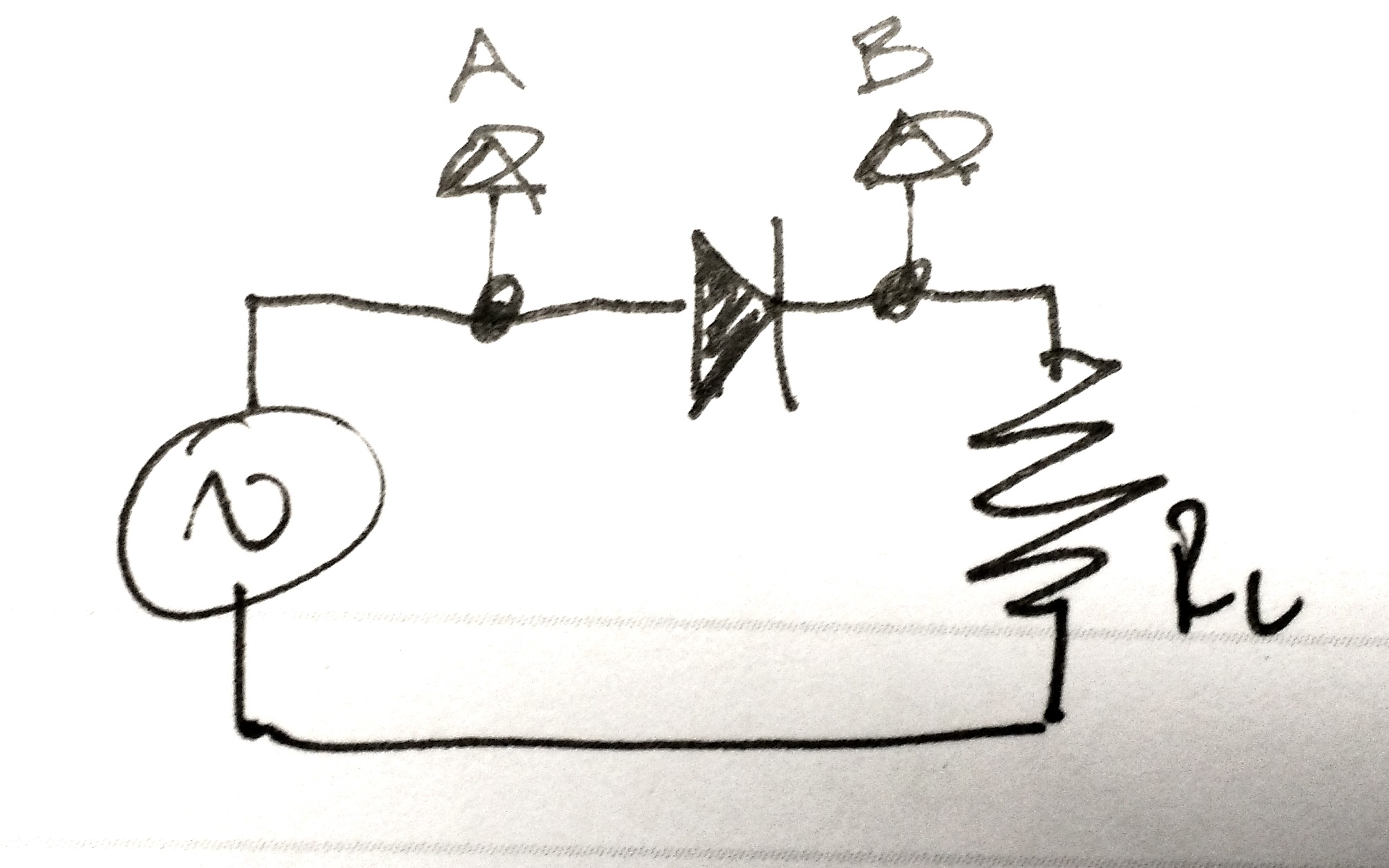
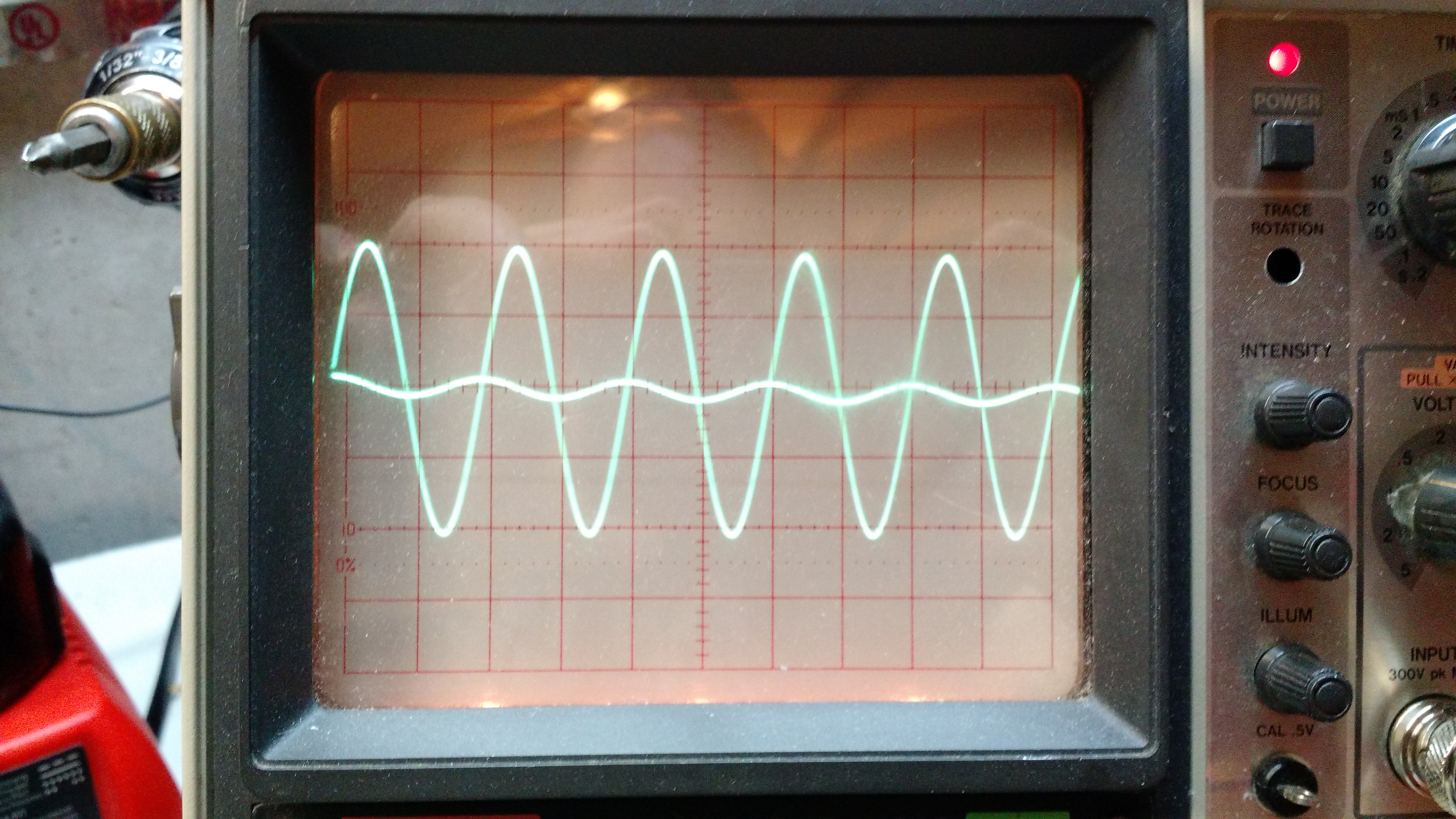
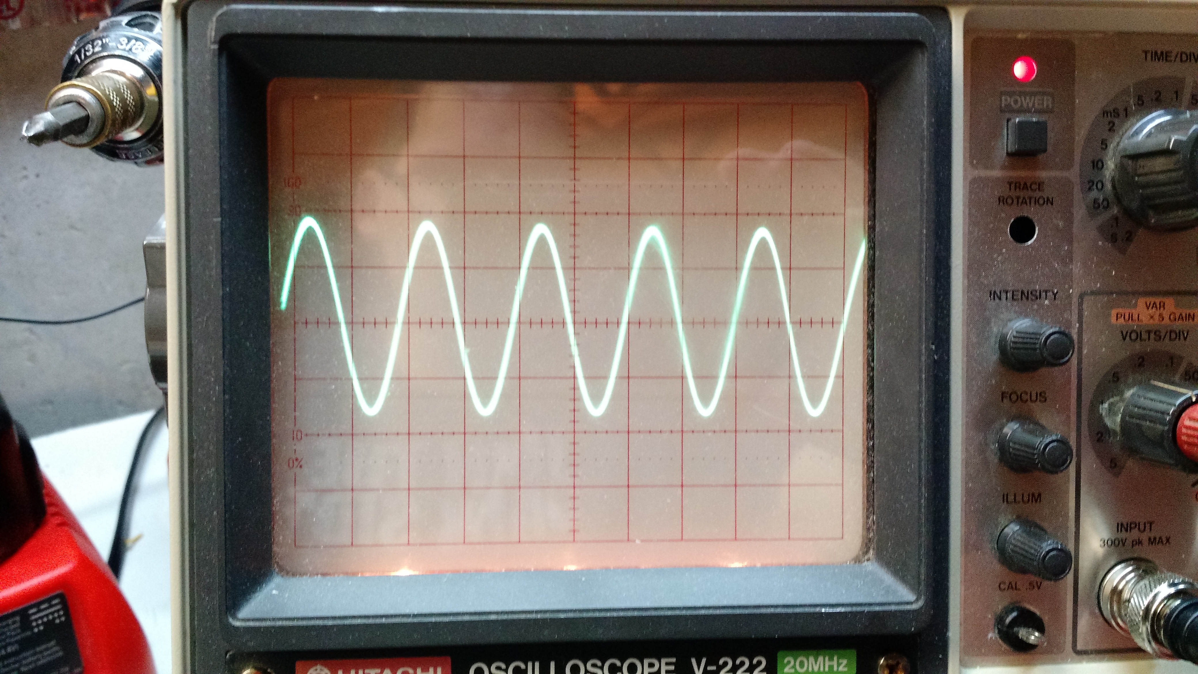
Experiment 1: Just a diode
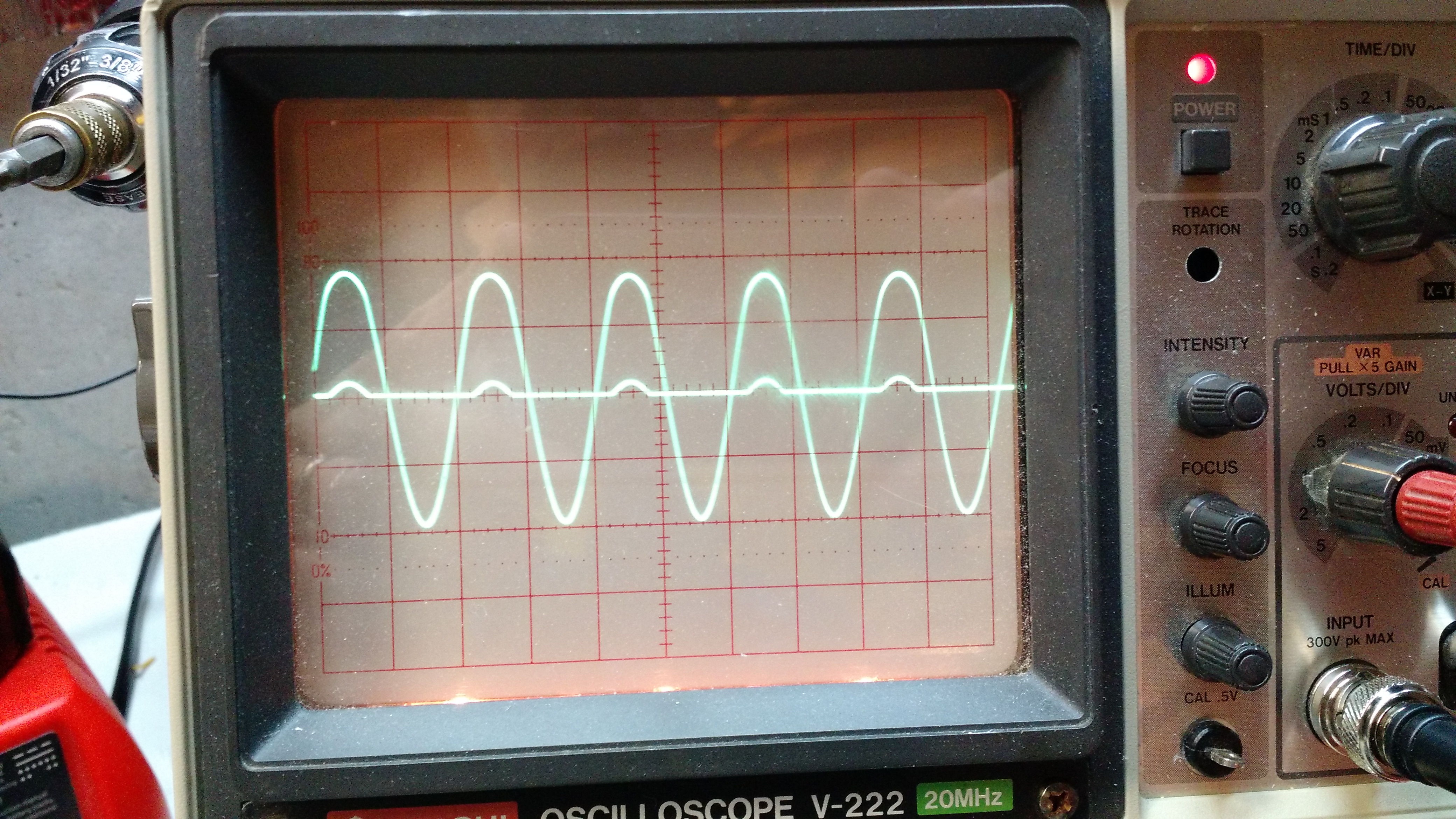
Result 1: the large waveform is the input signal (A), and the small bumps are the scope channel 2 (B). The diode rectifies the signal, which is why the bumps are only going up (and not down). The forward voltage drop on the diode is why the bumps are so small.

Experiment 2: a diode bridge
Result 2: This is similar to the circuit above, just more voltage drop because more diodes are involved.
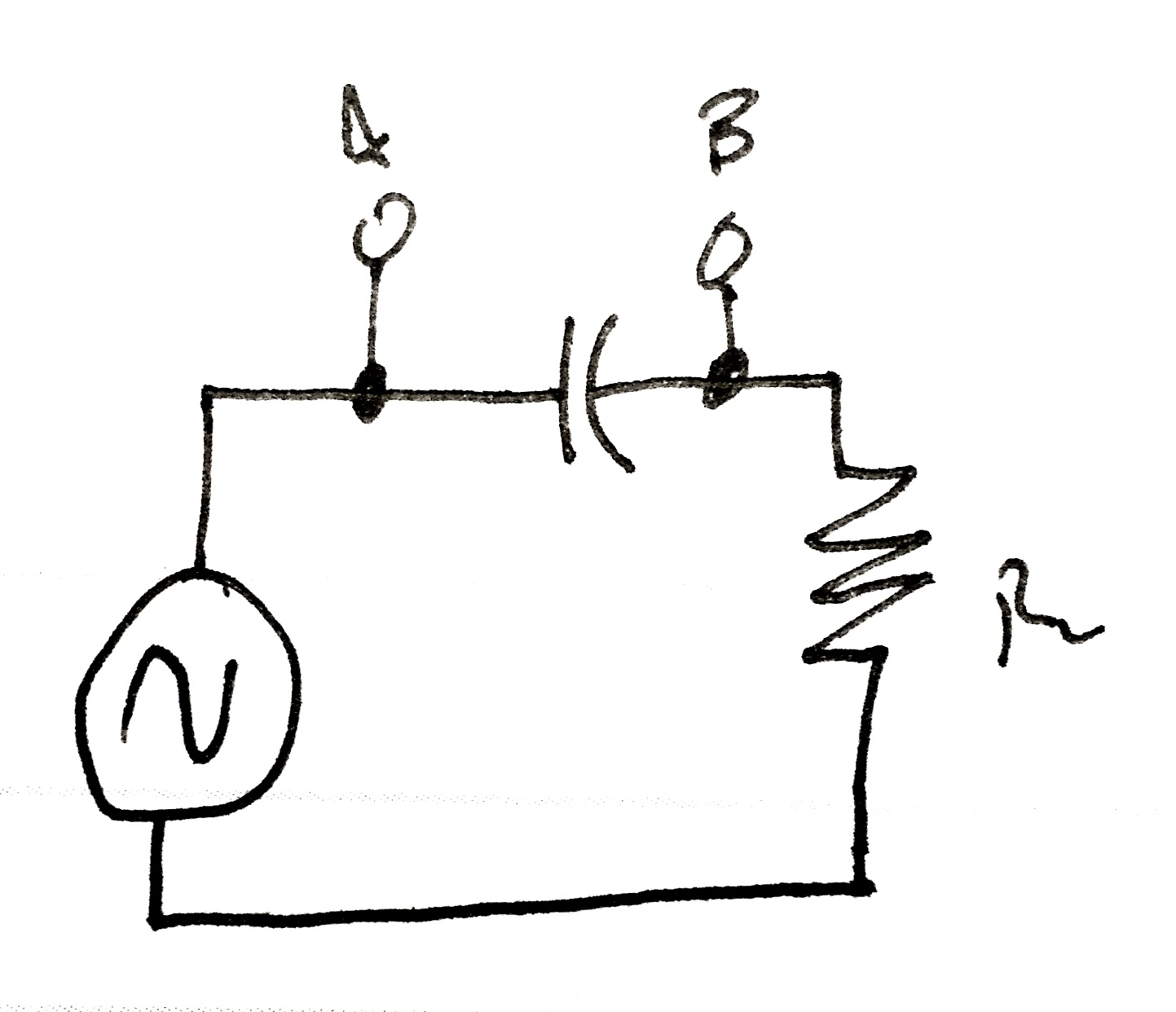
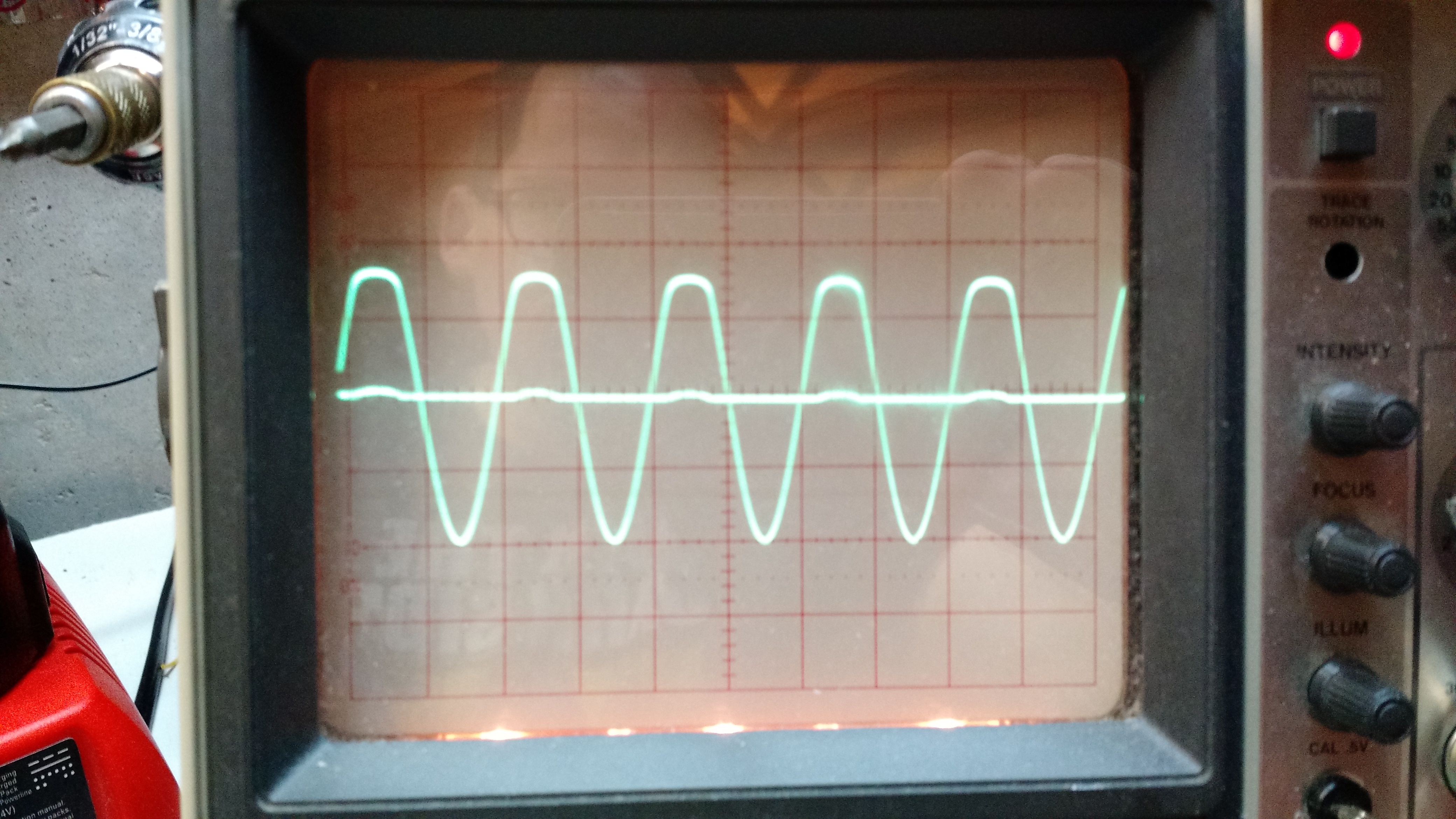
Experiment 3: Through a capacitor
Result 3: the capacitor blocks DC, but allows AC through, with some voltage drop.
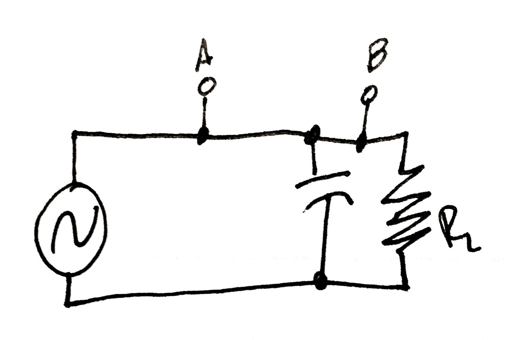
Experiment 4: Capacitor parallel with load.
Result 4. No change because there is nothing between the test points.
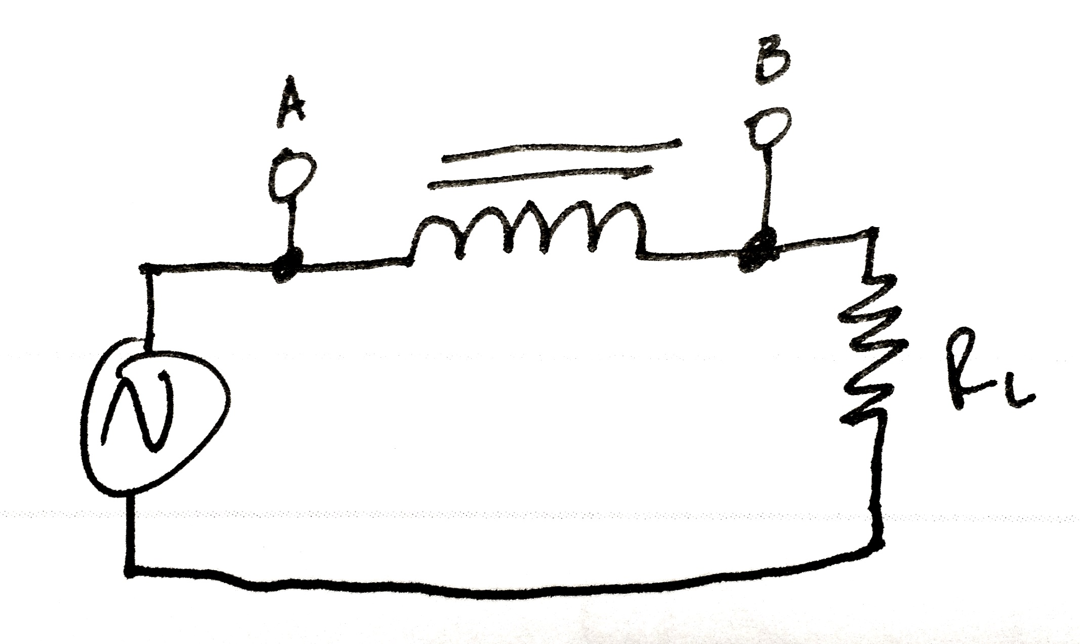
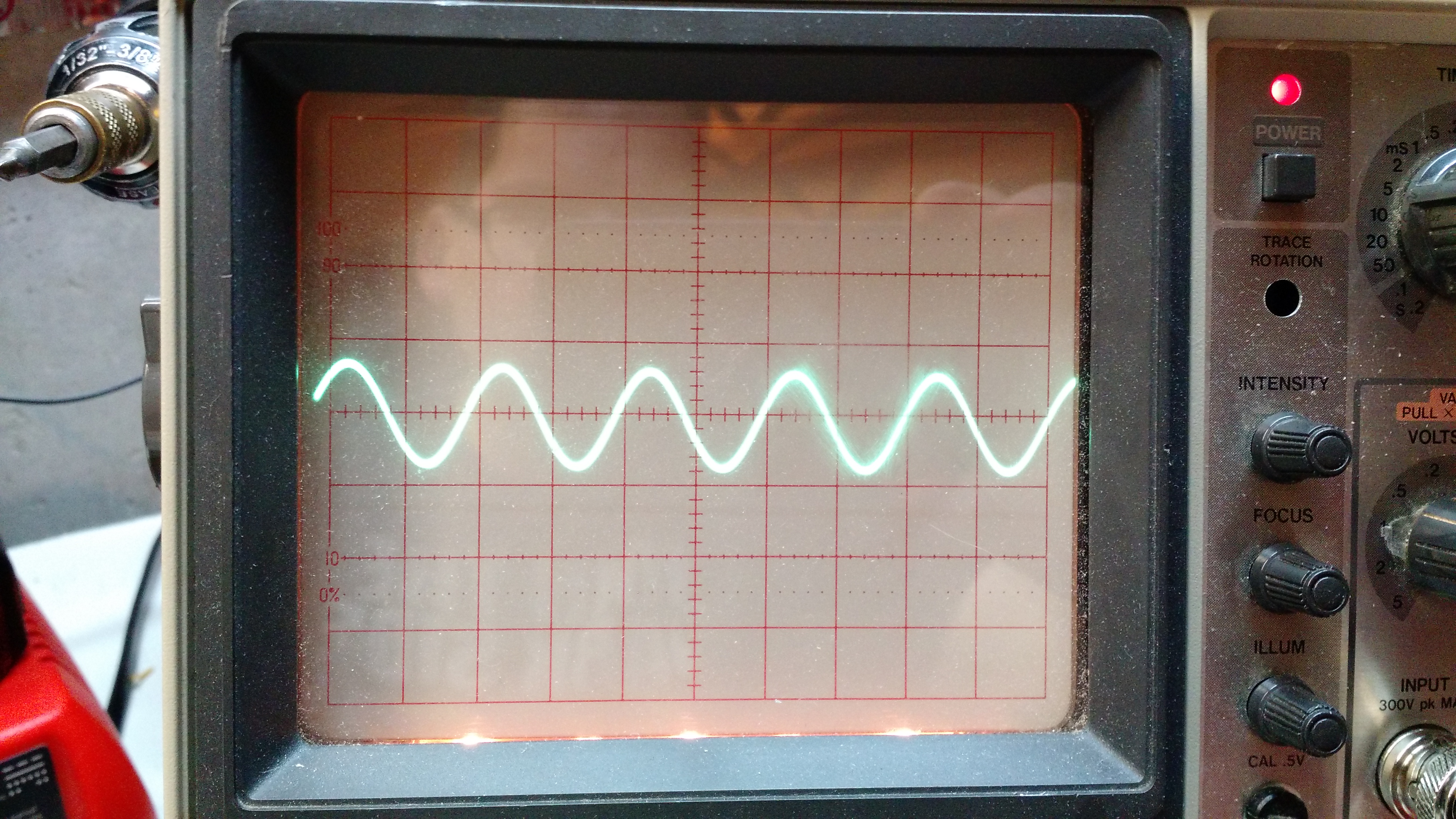
Experiment 5: through an inductor
Result 5: there was no change.
Experiment 6: inductive load
The video below shows what happened. I’m sure there’s an explanation of the instability, but I don’t know the explanation.
Stay tuned for experiments 2!
73 de KE8P
I’m not going to call it a spectrum analyzer anymore – the way I’ve designed this, it isn’t going to do the same things as a spectrum analyzer.
The main difference is that a spectrum analyzer can operate without a signal generator, this won’t because the signal generator is what is going to tell the Arduino what the frequency is.
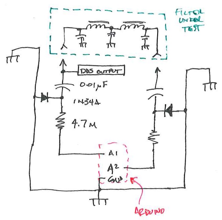
I built another shield to stack onto the shield in last week’s post.

There is currently no connection from the DDS to this yet, but that’s one of the only few things left to do on the hardware side.
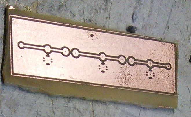
I also built a filter that will ultimately be the first filter to test. This is for my Softrock 20/30/40 and should pass 7 MHz while filtering 14 MHz.

This will fit in a Radio Shack small plastic enclosure – the plate was leftover from a small dummy load that I glued into the enclosure.
-73-
I’ve been reading a lot about receivers, and it sounds like one important thing is filtering. It makes sense too – simple receivers can suffer from front end overload due to a strong signal. And when on the ham bands, you never know where that strong signal may be – it could be someone driving down the road (which is a bit obvious once you see it), but in my neighborhood, if you don’t know me, you’re probably not going to know about the antennas in my attic.
I don’t have a spectrum analyzer, and since I’m a traffic engineer, I really don’t have access to one. I don’t need a full-blown spectrum analyzer, either, I just need to sweep through the HF band and get the difference between signal input and output. Math will take care of the rest.
$$dB=20*\log{\frac{V_{out}}{V_{in}}$$
The way I figure it is this:
An Arduino (and this could become a Raspberry Pi or any number of other devices, but I’m going to use an Arduino because it’s cheap and relatively durable) controls a direct digital synthesizer (DDS) module that just scans through it’s limits… well, probably something like 0.5 MHz – 40 MHz – that gets me into the AM broadcast band (which can be a source of strong signals) to above the 10m band (I don’t know what’s up there, but whatever’s there is probably not running 50,000 watts).
The output of the DDS would have an RF voltmeter and a probe to go to a filter. There would be another RF voltmeter to sense a filter output. The Arduino would handle not only control, of the DDS, but also sensing the voltage.
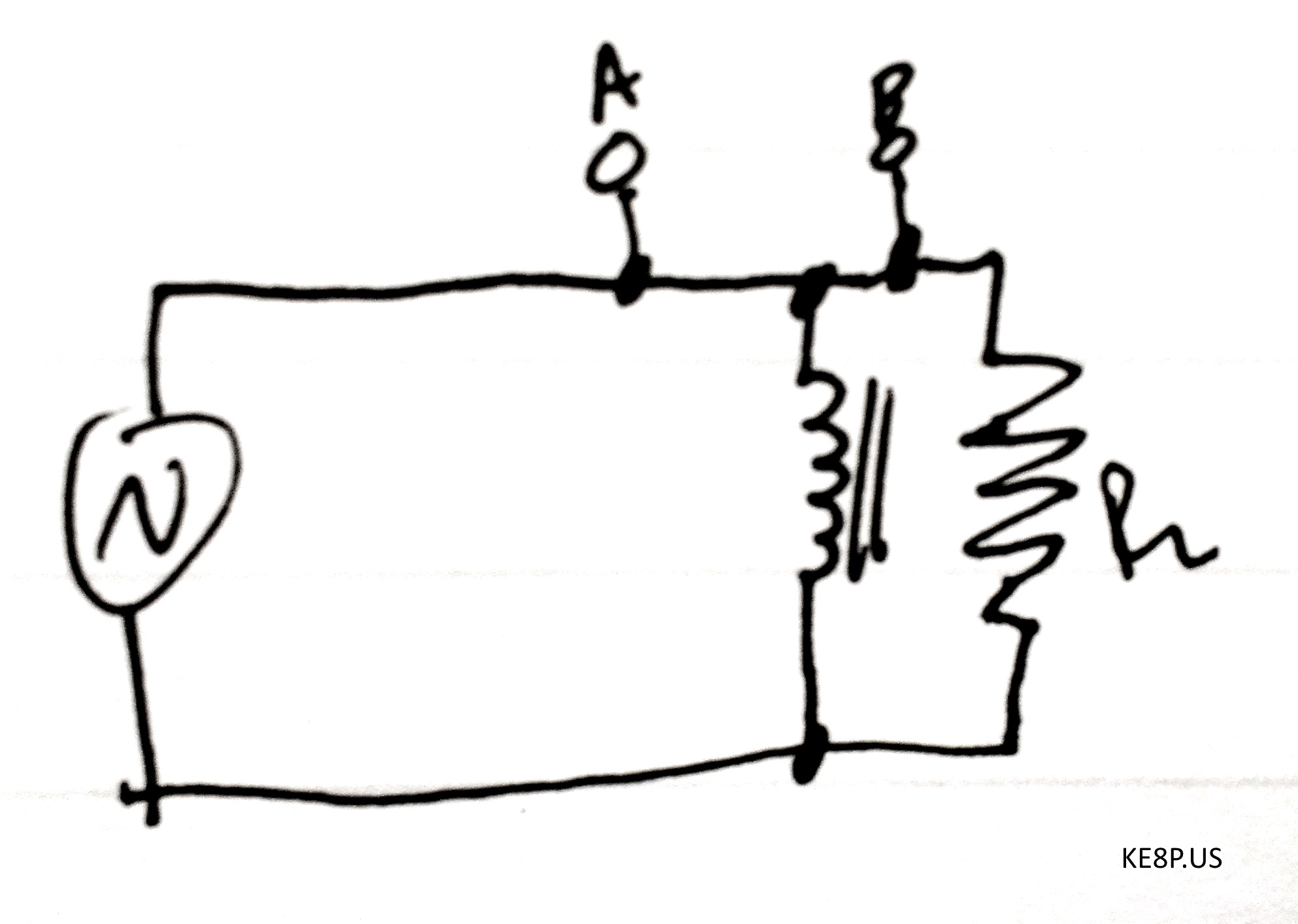
It’ll look something like this:
This is a block diagram/schematic of how this will work. I didn’t include the DDS module, which would be tied in there somewhere.
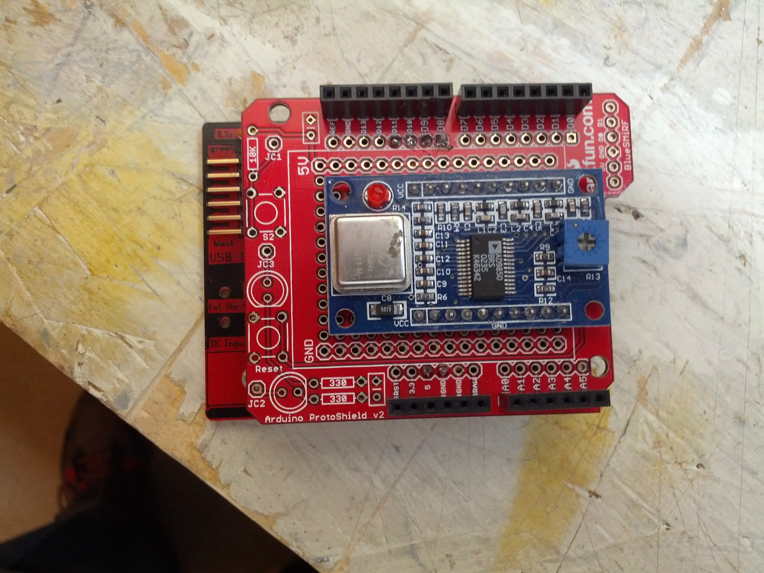
The Arduino and DDS will look like this:
There will have to be a companion app to this. In Java (not just because I’m drinking coffee, but also because it’s cross-platform). It’ll look like this:
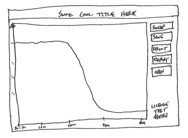
This is likely how things would look. Simple. A button that tells the Arduino to sweep, and some other important buttons.
I have the perfect item to test with also. One thing I built and don’t use (and never truly finished) was my Softrock RXTX. I need to build a filter for the output to keep the harmonic of the 7 Mhz fundamental from being too strong on the 20 meter band. I wound the coils while watching the Super Bowl-over-the-Broncos and printed a circuit board just before the game started.
Easy and small, but for 0.95 Watts, you don’t really need much.
I’m not really sure if this will work, but it certainly seems like it would, and I think it would be interesting to see how some filters respond on this compared to a real spectrum analyzer.
-73-