
Tag Archives: electronics
Somehow I ended up finding a Tessel GPS on Seeed Studio for $20 (it’s not $20 currently, but maybe someday soon). The Tessel GPS is really a Maestro A2235-H GPS chip on a semi-convenient breakout board.
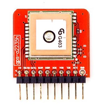
Tessel GPS Module
I want to use it with a Raspberry Pi Zero-W.
The problem is that the GPS output appears to be a newer type of data called OSP. It’s not easy to read, and I didn’t find any pre-built libraries that decode it. If one slows the baud rate down, the output is in NMEA, which is standard and free libraries exist.
Raspberry Pi-0W OS Setup
I’m assuming the use of Raspbian here.
Recommended first-time setup courtesy of Adafruit.
A few things need to happen on the Pi-0W: turning off the serial console.
- $sudo raspi-config
- Option 5: Interfacing Options
- P6: Serial
- No, you don’t want the shell accessible over serial
- Yes, you want serial port hardware to be enabled
- Finish
- $sudo shutdown -h now
The last command is shutdown because at this point, I’m assuming the hardware is not plugged in.
Raspberry Pi-0W Hardware Setup
The Tessel GPS breakout has the TX and RX inverted (depending on how you look at it). Pi-0W pin 1 to the Tessel GPS 3V3 power, pin 6 to the Tessel GPS ground, pin 8 to the Tessel GPS TX, and pin 10 to the Tessel GPS RX.
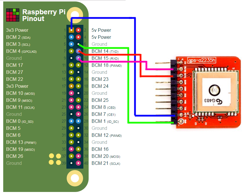
Tessel GPS Hookup Diagram
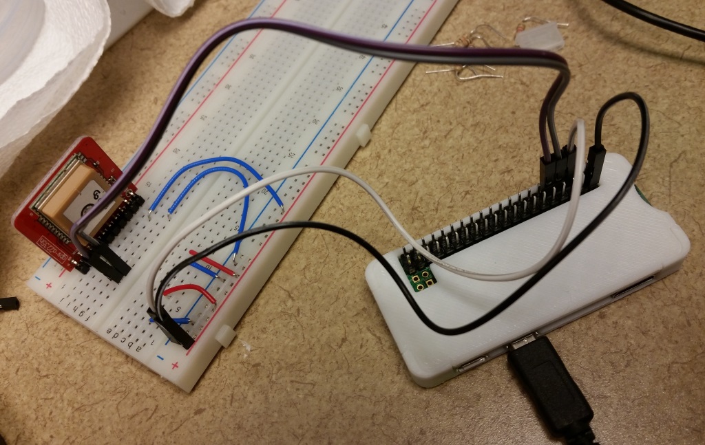
Live-ish Hookup Diagram
Reading From The Device
When the device is first powered on, any serial connection prints gibberish because the GPS strings are in hex. To change that, one must send a string of bytes to the GPS device. I’ve prepared a quick python script to do just that:
Once this script is run, any serial connection can be made to the GPS device, such as:
$sudo minicom -b 9600 -o -D /dev/serial0
Or with python or another language.
I’ve had a sudden want and need to print a few PCBs. I’m not going to re-hash the toner transfer method that everyone else has documented, but I will note three things that I’ve learned:
- Sanding the PCB with 600 grit sandpaper and cleaning with denatured alcohol is a must (you could probably use acetone or isopropyl alcohol too, the idea is to get any oil or dirt off the copper
- HP Banner and Flyer paper works fine for this. That may be documented somewhere, but everything I see says to use a photocopier and manually feeding magazines through it. I’m using my own laser printer, so the idea of feeding magazine pages through it is a bad idea to me… now, if I was using a copier at the library or drugstore or gas station, I would have no reservations.
- This method is never perfect. Never.
- Drilling sucks. Design for SMT, if you can.
I’m working on several things, including a small guitar amplifier and an upconverter for my RTL-SDR. The upconverter is one where the PCB layout was supplied and I printed it. I put it on larger PCB than it called for, hence the crappy looking surround.
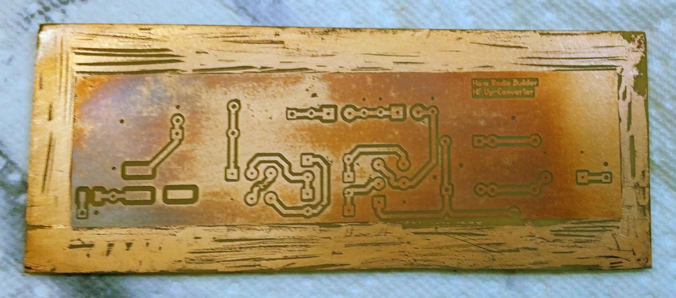
There’s some discoloration too, but that doesn’t seem to be an issue.
Prior to this, I did print two other PCBs. These were designs I did in Eagle. Both look like the PIC16 below (okay, the other, a real-time clock, was larger!). In both cases, these are just breakouts so I can use them with a breadboard. I forgot that I have a set of small drill bits somewhere.
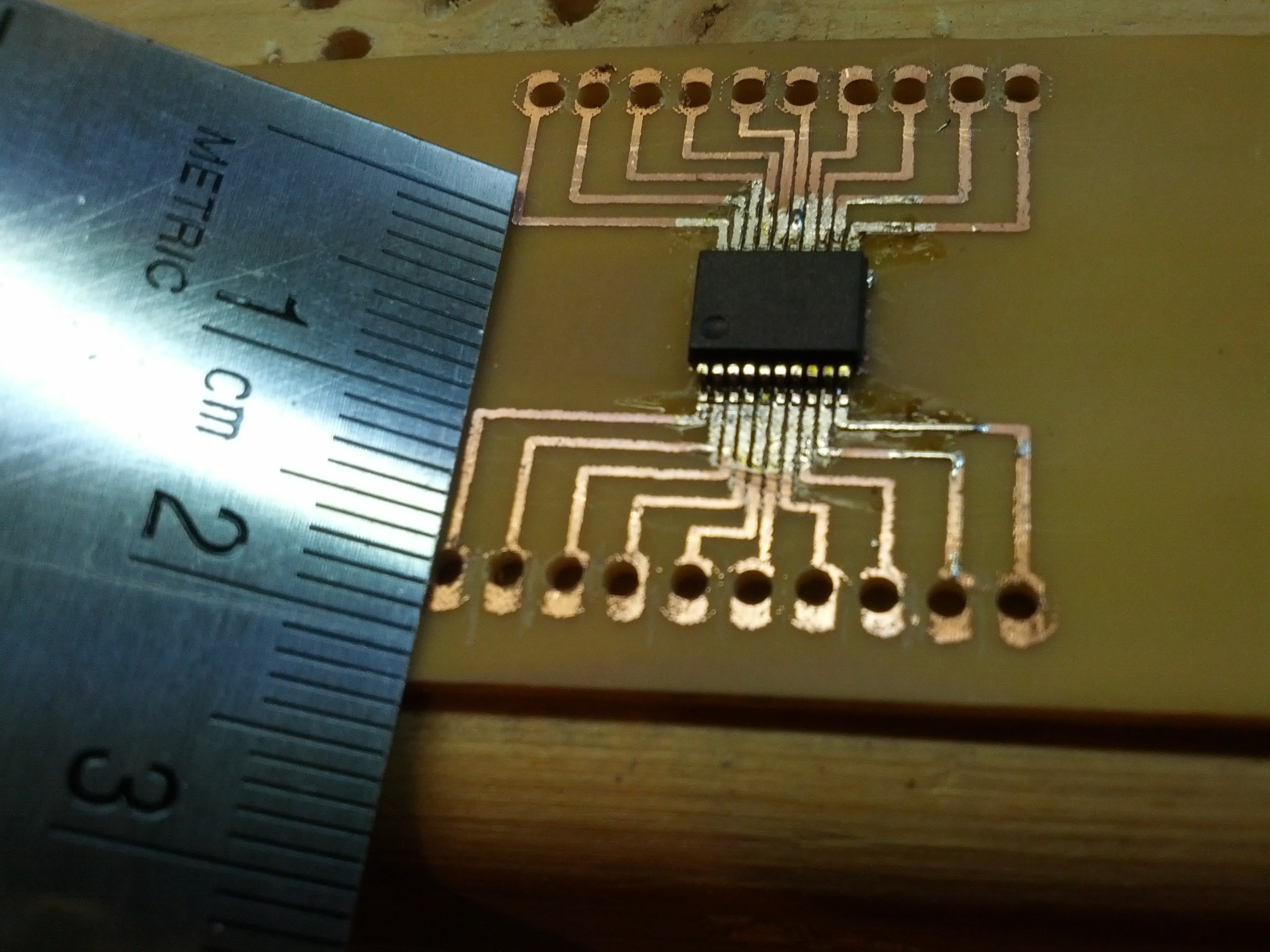
Yeah, this PIC16 is dinky!
Moving forward, I will be using both the software and techniques used by Contextual Electronics as noted on this page on kohanbash.com. The videos are EXTREMELY HELPFUL! I may still print prototypes at home, but with all reality, I may just print the layout on normal paper and set the parts on the paper to fit them and then send the PCB off to a service.
A side note on printing these things at home. Rocking trays full of dangerous chemicals for long periods of time is only fun when you’re developing photos, and that ship has sailed (with my film camera, developing tanks, dark bag, and bulk film loader on the boat). If I do this a lot, I may end up building something that rocks the tray, as it would be pretty simple to build.
-73-
I spent the weekend building stuff.
RF Probe
First, I built an RF probe using a schematic from the ARRL Handbook. It’s a pretty simple build, as all I needed was a pair of old test probes, a germanium diode, a capacitor, and a resistor. I packaged the electronics in a small piece of CPVC pipe, which is nice and unobtrusive.
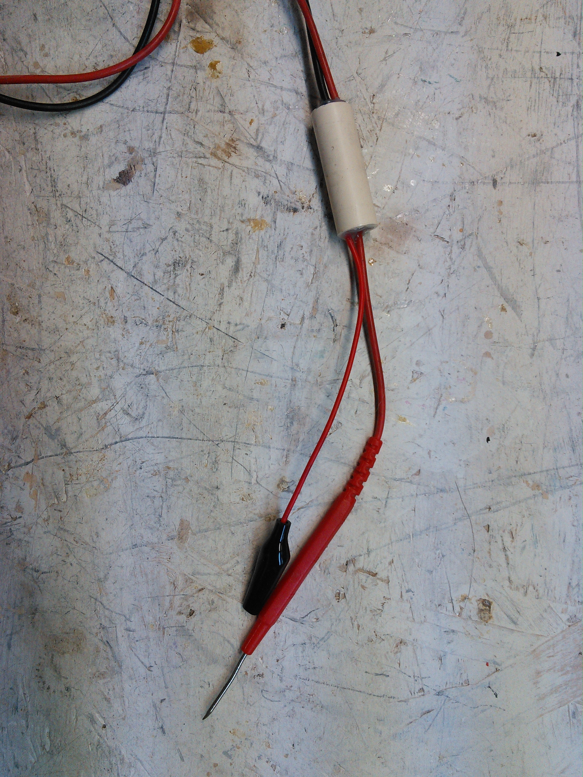
This is the RF Probe. It fits nicely in some 1/2″ CPVC pipe.
End Fed #2
After W0EA told me I used the wrong coil core material, I built one with the correct material (ferrite, not iron). I still have the old, so I’ll do some comparisons, but barring any major issues, I’ll stick with the ferrite one.
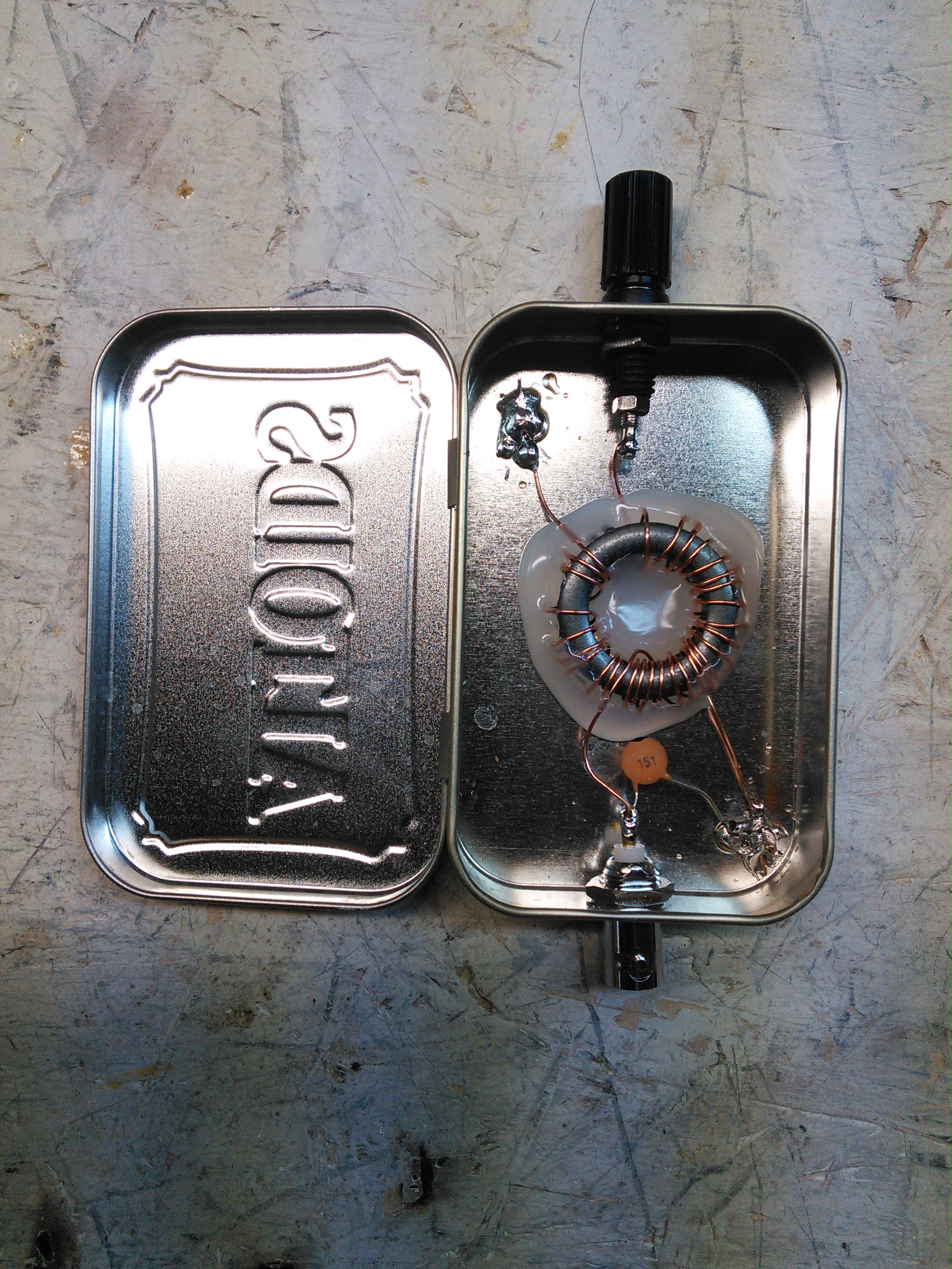
End Fed #2.
-73-
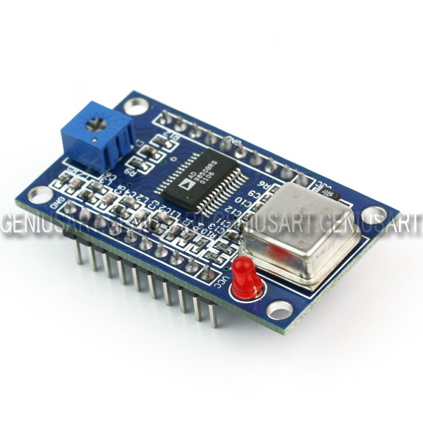
After reading a few blog posts out there from others, I decided that it would be interesting for me to get hold of an AD9851 module. My initial plan is to build an antenna analyzer and something else (I bought two).
The major engine of these modules is an AD9850 Direct Digital Synthesizer. This chip can be purchased in quantity for $15.25 EACH from Newark. From Digi-key, $15.37.
The two modules I purchased on eBay were $8.90. Total. With shipping.
And these modules aren’t just the chip…
So I don’t totally understand how this eBay seller makes money, but it appears he does (it appears he’s/she’s sold quite a few of them, based on their eBay feedback rating). What I do (now) understand is why we no longer do electronics manufacturing in the USA.
After ordering this (at the time of writing, I’m still waiting on shipping), I started looking in to adding Ethernet capabilities to one of my Arduinos. So I looked in to the ENC28J60-based chipsets. After finding one for £22.90 and one for $35 on Sparkfun, I looked on eBay. $4.09 each from Hong Kong. $2 for shipping. At least this isn’t as egregious as the AD9850 modules, as the ENC28J60 chip is $2.36 in quantity from Digi-Key.
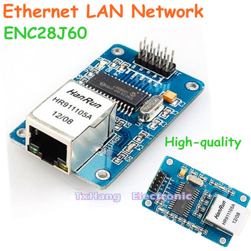
I can’t imagine this is news to anyone in the electronics industry, but I’m just an amateur radio operator and traffic engineer. I found this interesting. And I’m not complaining, as long as this stuff I get from China works! 🙂
Of course, there is a drawback to this – the wait. I got a confirmation of shipment for the DDS modules on March 26, 2013, and they arrived on April 6, 2013. I ordered the Ethernet modules on April 5, 2013, and they have yet to arrive. So there is a delay, but with some planning, a hobbyist like me can deal with it.
-73-
—UPDATE—
The Soldersmoke Daily News blog has another possible reason: a design flaw. See his post for details.
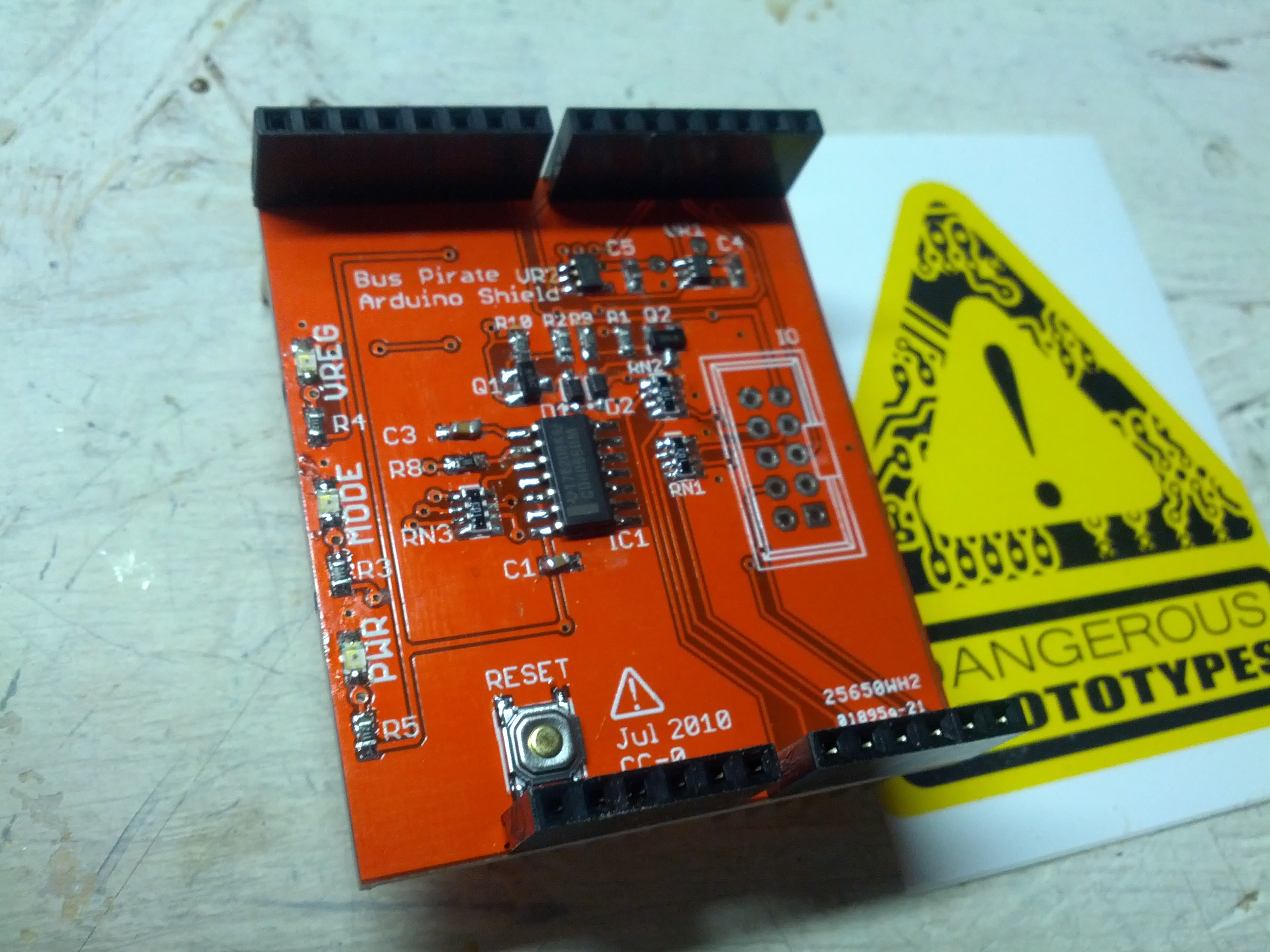
A few months ago I had the luck of winning a free PCB from Dangerous Prototypes via twitter. I finally got around to building it. Below are some pictures of the build. Please no comments on my soldering skills – I’m still a novice at SMD components. This is the second kit I’ve done with SMD components, and the other was only a handful of SMDs and mostly through-hole.
There is one part missing – I didn’t install the connector for the test leads. I forgot to buy it when I bought the rest of the components (and it wasn’t actually the only thing I forgot).
-
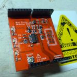
- The top of the board
-
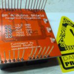
- The bottom of the board
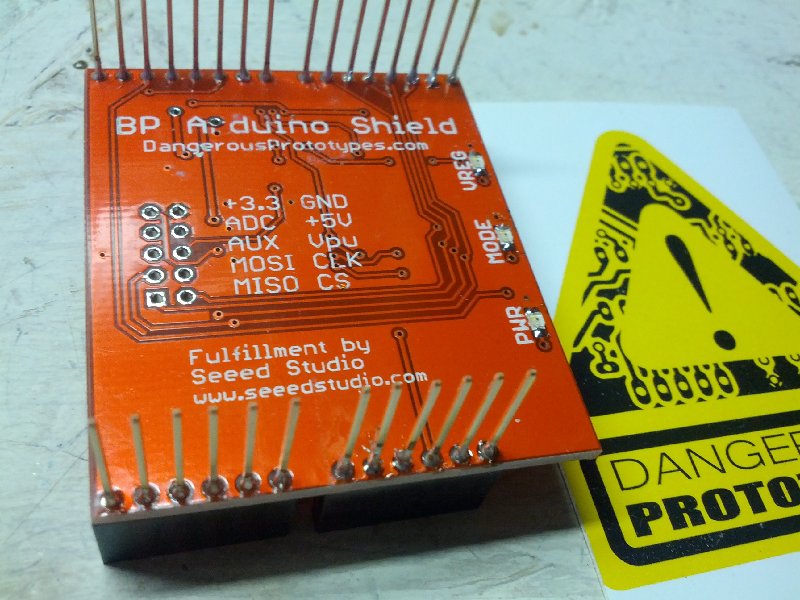
-
- The top while attached to an Uno. I did use different LED colors (green for power, and yellow for mode and voltage regulation).
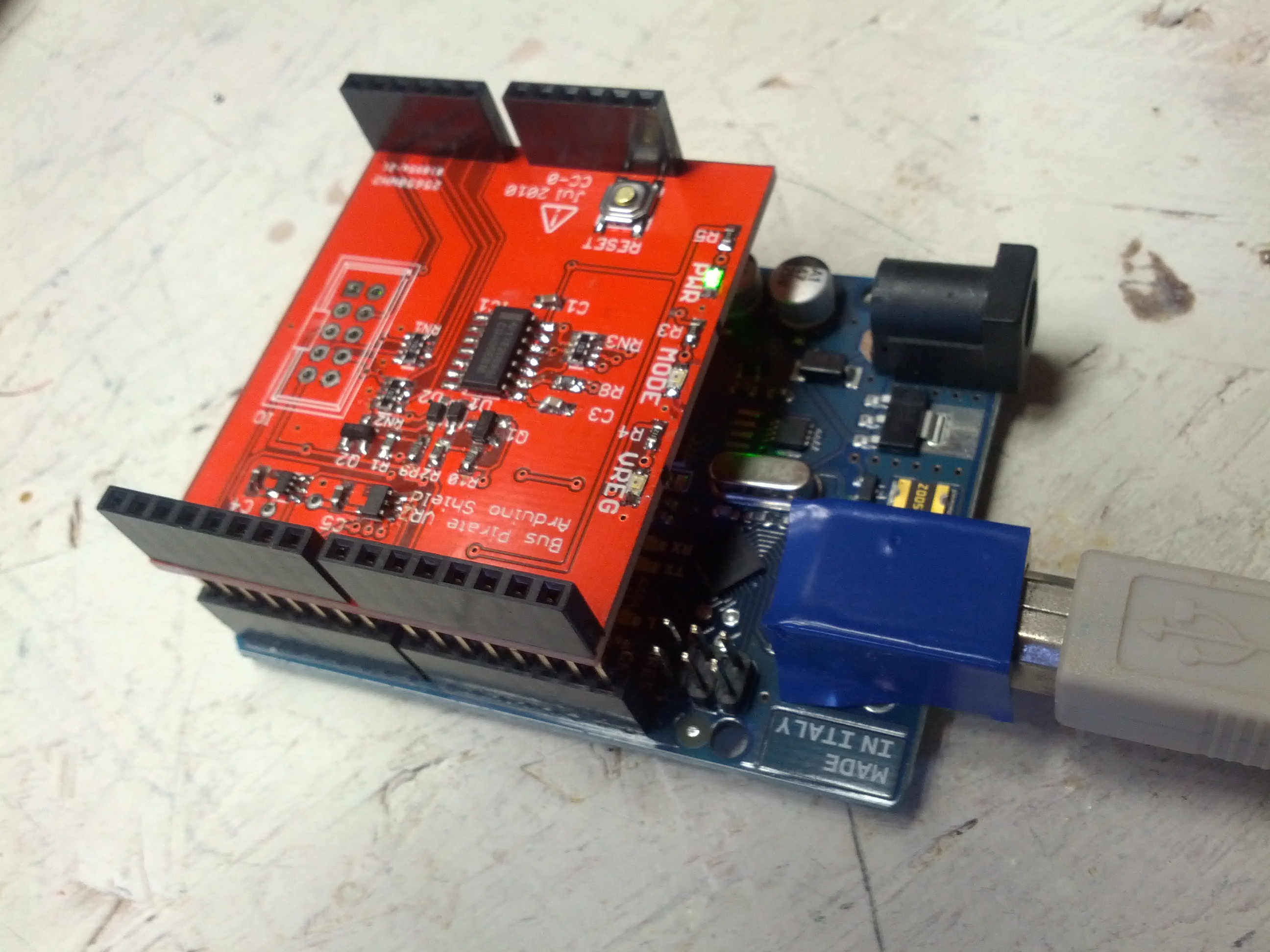
This was a fun build, but it did underscore my need for a new soldering iron for SMD items and a new tip for my general purpose soldering iron (which is really too hot for SMD, but so far I haven’t burned anything up).
Now all I need to do is figure out how to use this thing! 🙂
-73-
I am considering building a frequency counter. In part of that, I’ve been learning and playing around with logic chips. I started by playing with a few decade counters and setting those to count based on pulses from an Arduino. As I continued, I felt the Arduino was too slow and replaced it with a 555 timer used as an astable multivibrator and only used the Arduino as a power supply. Then, just to mess around, I put a photoresistor on it and used it to adjust the frequency. Below are the Fritzing image and a video showing how it works.
")
I am working on a Realistic (Radio Shack) HTX-100. I purchased two of these for $45 last May, and was told “one works, one does not”. I joined the HTX-HF_Tech Yahoo group and started looking into things.
The initial problem (but not the ONLY problem) was that there was a lot of static noise from the speaker. This noise was internal to the radio (thanks to a troubleshooting tip I got on Google+ that told me to short the antenna center to shield at the back of the radio).
I started poking around at things, and found that a trimmer resistor was dirty and was causing the static. Combined with the fact that the speaker was desoldered from the board (an oh-so-difficult fix!), I thought maybe I fixed it.
Then I hooked it up to an antenna and checked its ability to receive. Nothing. I could tune stations in on one HTX (and on my Ten-Tec), but not on this one. In fact, I couldn’t tune anything.
One of the things available (not only on the group but also from a few additional websites) is a repair manual, which is really very helpful. I started into the alignment procedure and noticed that in step 3, I was nowhere near the target value of 10.695 Mhz, and was not able to adjust to get anywhere close. So I started looking at the troubleshooting section for the PLL board (where the coil in step 3 was located). A few steps in the process, I checked voltages on one of the ICs and found a handful of them off. I started checking further, and questioned a crystal. I replaced the crystal and found no change. So, I started looking at other things. I checked the voltages on other ICs and found a handful of others that are off. I looked at capacitors, and noticed a few that have tears that seem to indicate that they’ve failed. I replaced one that I happen to have, and it fixed one of the voltages on one of the ICs. Progress! I have a few more to do, but I need to order the parts.

Blown Capacitors on the HTX-100 PLL Board

Main Board of HTX-100

PLL Board of HTX-100
-73-
Last summer, a friend brought me an Astron RS-35 Power Supply to repair. It had been involved in a near-lightning-strike experience that fried the loading coil on an antenna, among other things. The problem was that as soon as the supply was switched on, it would blow the fuse. The only thing that was obvious was that something was causing the SCR crowbar circuit to fire and blow the fuse to save the power supply.
I started out by checking the bridge diodes and filter capacitors. All seemed fine. I checked the pass transistors and those were fine. During a last resort, I removed an electrolytic capacitor and replaced it with another of the same value, but less voltage. My hope was that the voltage on the original capacitor was unnecessary, or that I would have enough time to test a few things before it blew.
Of course, it never happens that way. I had about 15 seconds (not enough time) before letting the magic smoke out of the capacitor. So, since I’m not an electrical engineer, I decided to run a few tests on the blown cap. I noticed that there was no physical damage to the capacitor EXCEPT a small hole in the jacket.
So after staring a little at the schematic (there is an awesome resource on the Repeater Builder website), I decided to remove a capacitor (C6 on the schematic image below). It seemed like a likely possibility, since this was part of the SCR firing circuit (the part I circled in orange highlighter).

Low and behold, it was it! I replaced the part with a new one, and the power supply is done!
-73-