
Tag Archives: ftdi
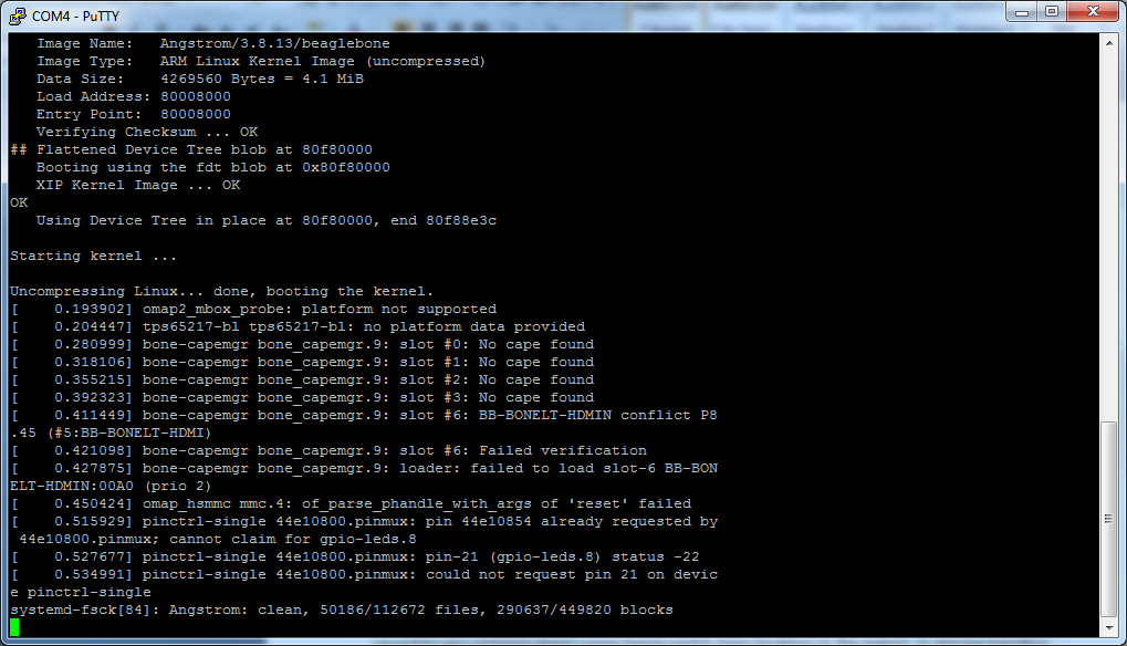
I’ve been playing around with my BeagleBone Black quite a bit recently. It all started with one of my coworkers bringing in a rain gauge that we had collecting dust somewhere in an office storage room. I had been installing software to the BBB and ran out of space on the eMMC (internal memory) chip. So I tried to boot from an SD Card – the one I updated the BBB to the latest software with and still loaded with the image. It appeared to me that it maybe had been reloading the eMMC, but I couldn’t tell for sure. After around a half hour, I power-cycled the BBB. Bad news, it wouldn’t boot. I don’t have the correct HDMI cable, and I’m at work, so my resources are pretty limited.
Enter the FTDI port on the BBB. Enter the fact that I don’t have an FTDI cable at the office. D’oh!
But I have a few Arduino Unos.
I wondered, and then quickly looked on the Internet to find a page on Instructables that describes how to use an Arduino as an FTDI programmer. I then looked at a reference for the pinouts. A page at Circuitco has the pinouts that seemed like they’d work – ground, RX, and TX. I hooked them up and…
It gets a little bit more MacGyver-ish. I have only a small box of jumper wires at the office, a few shield headers, and a breadboard…
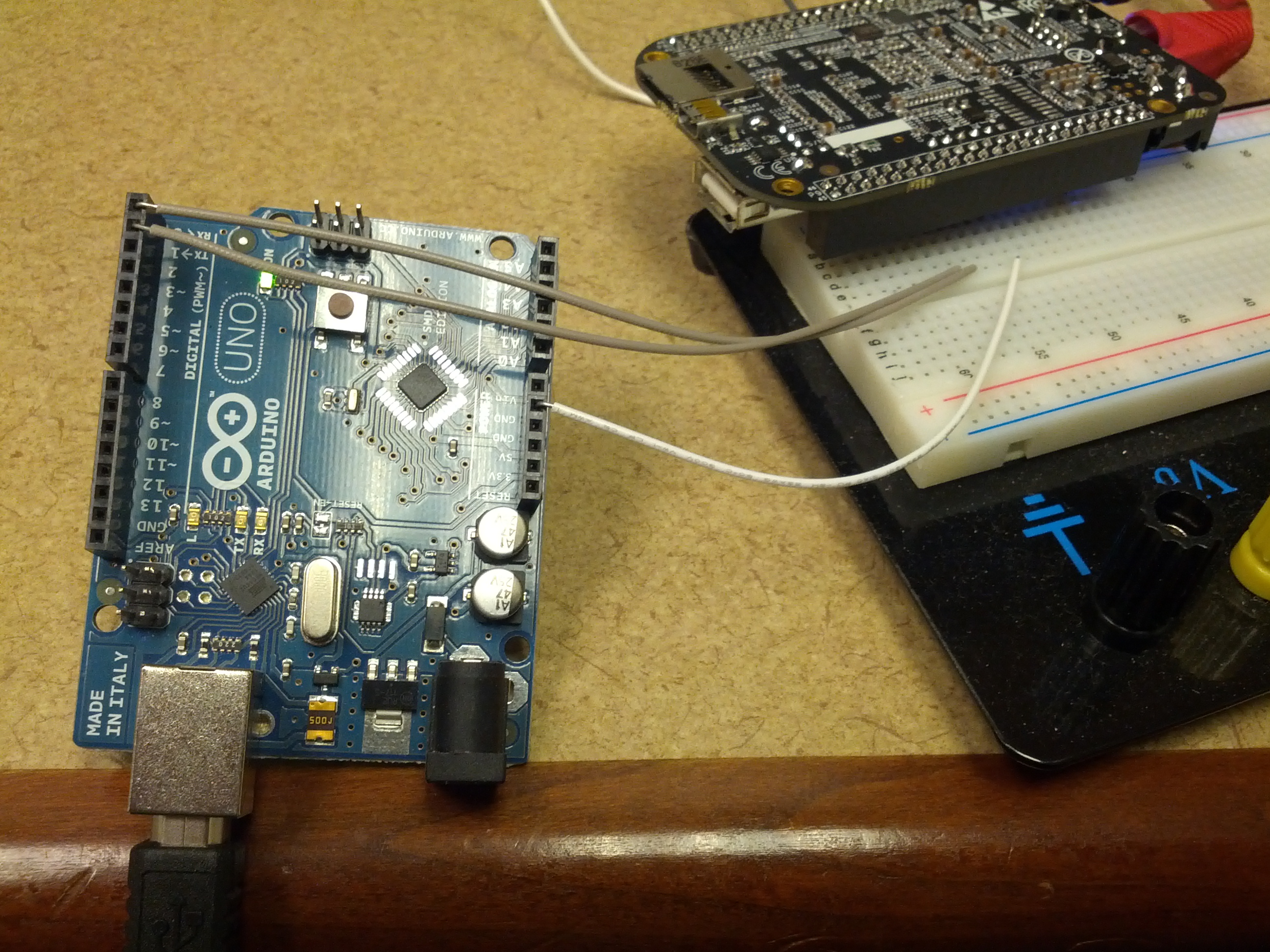
This is an overview of the setup. The Arduino RX, TX, and Ground are connected to a breadboard that has a shield header that connects to the BBB’s FTDI port.
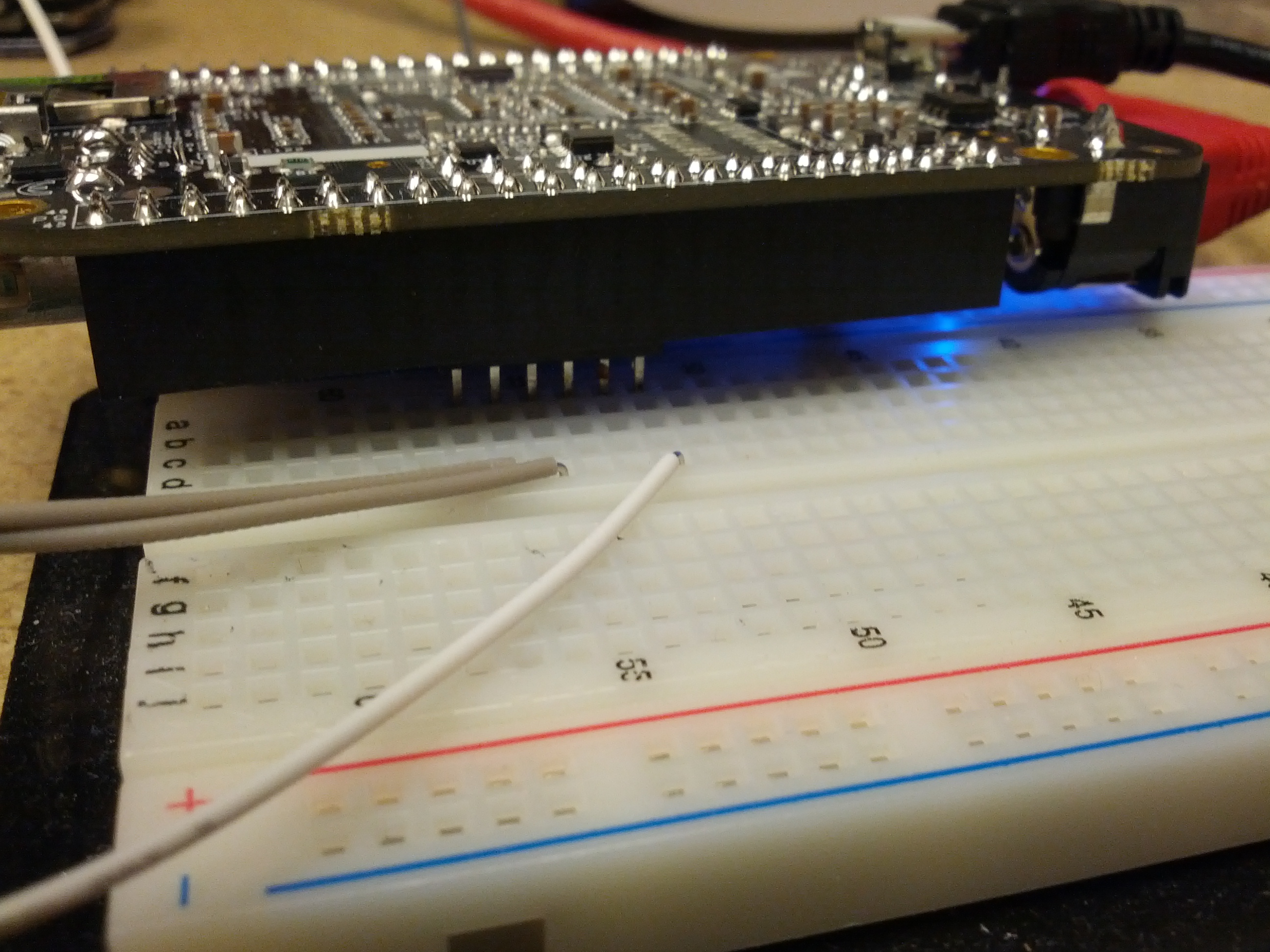
This is the connection between the breadboard and the BBB.
I decided to move all my radio stuff from my desktop to my laptop for now. My desktop has never been a reliable computer – there’s something wrong with it that causes it to stall (and whatever it is, it’s hardware and not OS, as it has done the same with XP or Mint). It also goes SLOOOOOOOOOOOW. In fact, it goes so slow, I tend to boot it at least 10 minutes before I need it, and it was degrading to the point where it wasn’t even ready then.
So, one thing I ~need~ want to be able to do is digital modes like RTTY (I know many hate it, but I do enjoy RTTY contests). The problem I ran into is not a new one: there’s no serial port on my laptop, meaning my old way of triggering my radio’s PTT is now a useless group of components.
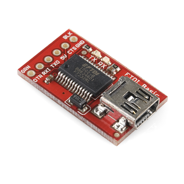
I happen to have a Sparkfun FTDI Breakout board sitting nearby. It has a damaged trace to the 5V output caused by the fact that my soldering iron is an old Radio Shack 45W pencil (which puts out far too much heat for many boards). I had set it aside with the intent to use a wire jumper to fix the problem, but after getting it back off the electronic triage shelf I realized that everything worked except the 5V output. The module looks like this (picture credit from Sparkfun):
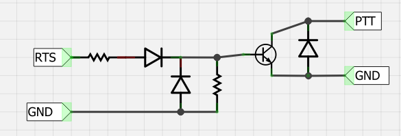
I first wired it in with my transistor switch to look something like this:
It didn’t work.
I started to investigate. I noticed that DTR, RX1, TXO, and CTS were all 5V, but DTR would drop to 0V when the DTR was activated via software.
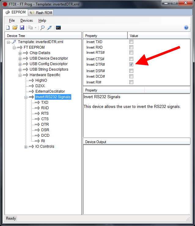
So I did a little research. FTDI makes their boards customizable, so I looked into the software from FTDI’s website and found a configuration utility called FT_PROG. From this utility, I was able to read the chip and then re-write the chip to invert the DTR signal. Note the screenshot below:
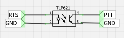
This allows me to use the FTDI board with an optoisolator and trigger the PTT. The schematic is below:
So now I just have to fix the USB soundcard issue…
-73-