
Tag Archives: hf
Before getting back into ham radio, I did something that I later found to be not optimal – I purchased a very nice 50″ plasma TV. It sounds like everyone else’s YouTube video of Plasma TV RFI, but if you want to see mine, the video is below.
I’ve looked into different solutions that remove noise based on a noise antenna, like the MFJ-1025 Noise Canceler. I believe these items work by inverting the phase of the noise and mixing it back with the signal to remove the noise. It is absolutely critical that these items have a great noise antenna in order to remove it.
The real issue I have is shown in the video above – the noise is picked up in the antenna. I believe that it is primarily picked up by the feed line because it is near (enough) to the front of the TV. See the diagram below:
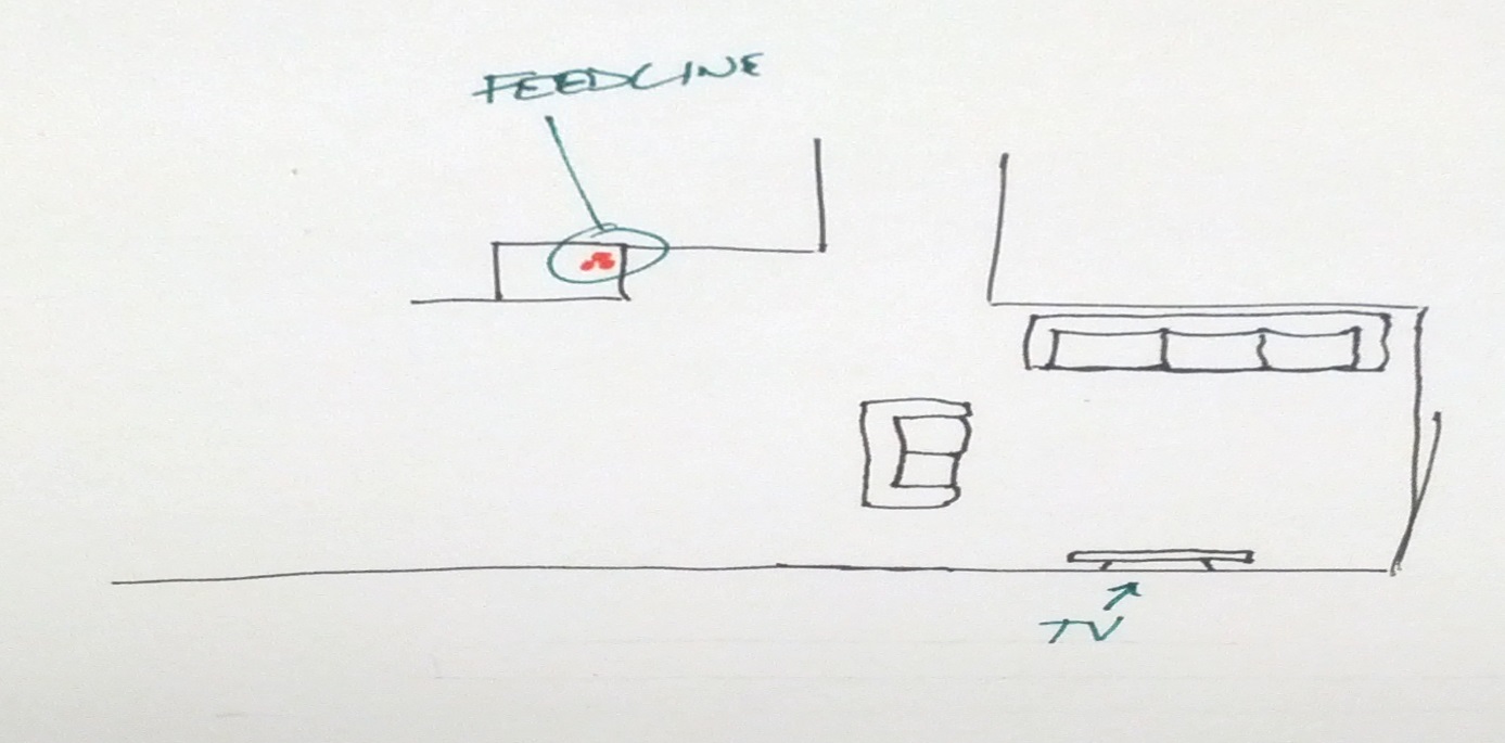
So in order to use a noise canceling device, I’d need an antenna along my feed line.
I decided to try something else first – shielding my coax. I bought a pair of lengths of EMT conduit to run the coax in. This has a second advantage of being able to run coax really quickly. The only disadvantage is that I can’t use ladder line in it. Given the situation, no big loss.
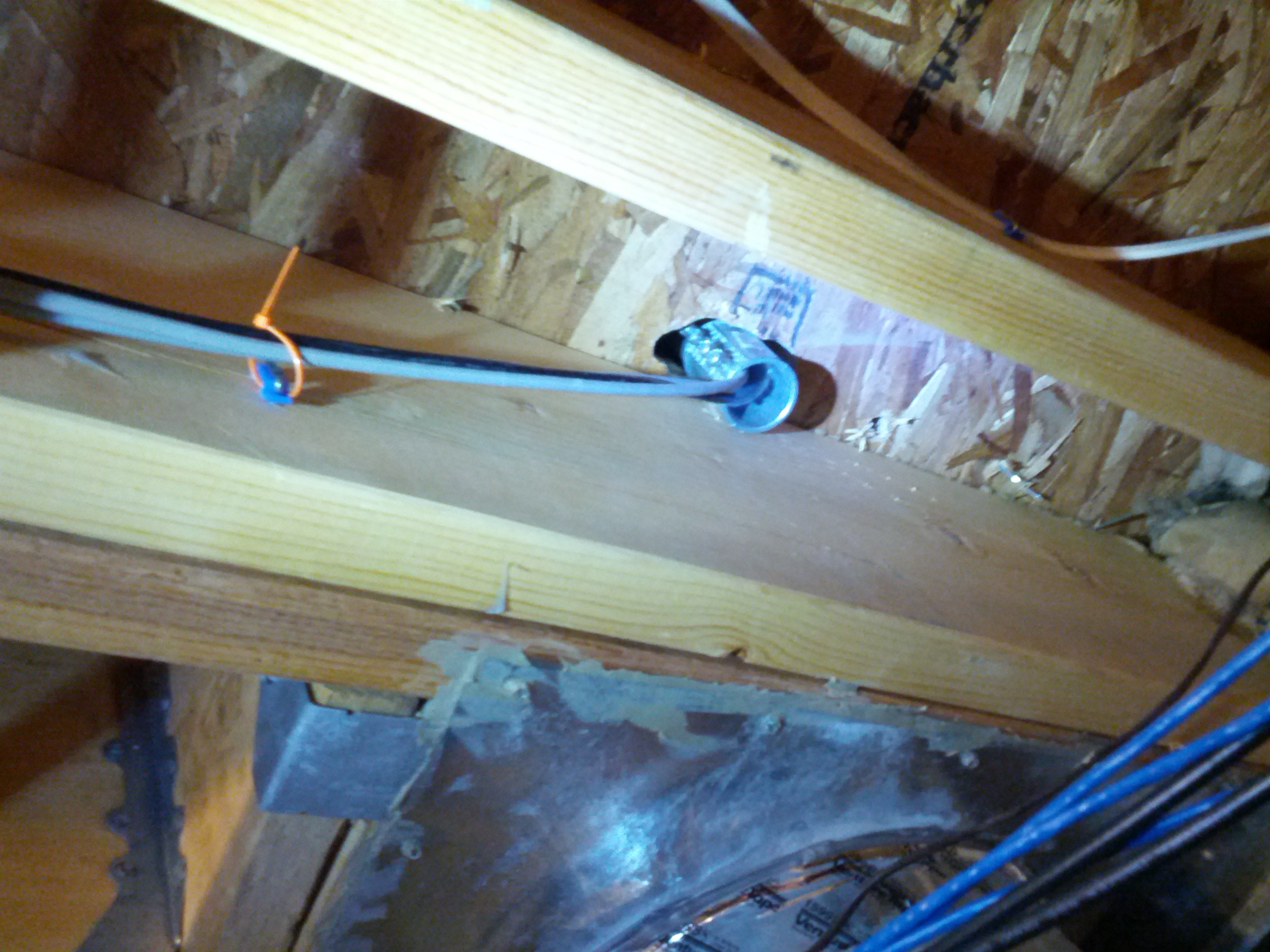
So right now, this is where I’m at. My HF feed line is crummy RG-58 that has an aluminum shield (insert angry face), so I haven’t tested it yet because I don’t have any crimp PL-259 connectors (nor do I have aluminum solder). Additionally, if this doesn’t work like this, I will ground the conduit to see if that fixes it. If neither does, I’m sure that conduit would be an adequate noise antenna for a noise canceling device.
In other news…
I’ve been virtually off the air because of a problem with my IC-706. I posted something to Google+ and received a response that I need to look into, but I’m still looking for more clues as to why I’m getting major static on FM receive.
The filter sweeper is “stalled” because of work on other things. I will be getting back into it because I may want (or need) it for that crystal IF filter problem indicated in the G+ post mentioned above.
-73-
So after spending last weekend looking over things, I put everything back EXCEPT the finals and the speaker. I rigged a little power cord with alligator clips (I don’t have another plug for this radio) and a circuit breaker on the hot line. I connected the hot to the fuse in the radio and the ground to the radio chassis and powered up the supply. I was greeted with the radio lighting up 21.2027 MHz. I couldn’t hear anything, as I had the speaker removed.

So the next thing I did was resolder the speaker and the the finals. After finding a nylon washer for the internal hot wire in the finals, I did the minimum replacement of screws and powered the unit back up. It immediately popped the circuit breaker.
Guessing that the finals were bad, I removed the finals and powered the rig back up. The display came back up, but no sound out of the speaker. I started adjusting the volume and RF gain trying to hear something. I then noticed that the mode switch was set to “LOCK”, so the transmitter was on. One thing I did notice is that no power was coming out – I had the internal antenna connection connected to my little QRP dummy load that has a rectifier output and I had my multimeter connected to it and there was no DC voltage coming through the dummy load and no read on the frequency counter in my antenna analyzer.
While there is a slight flaw in my troubleshooting, I’m fairly confident that the problem is the finals and I will be taking a closer look at the module tomorrow.
Incidentally, I looked up the price for new finals at RF Parts. $60 for a pair, and $25 for one. Of that’s the problem, it’ll be a fairly inexpensive fix.
Last Friday while sitting in the parking lot of my building, I tried contacting NR4CB or AB4UG to wish them a happy wedding day. It didn’t happen. I could barely hear Connie, could tell someone was there (but couldn’t make out the words) when Eugene was on. It didn’t help that other stations were 2 kHz above and 2 kHz below.
I got to thinking about running mobile HF again.
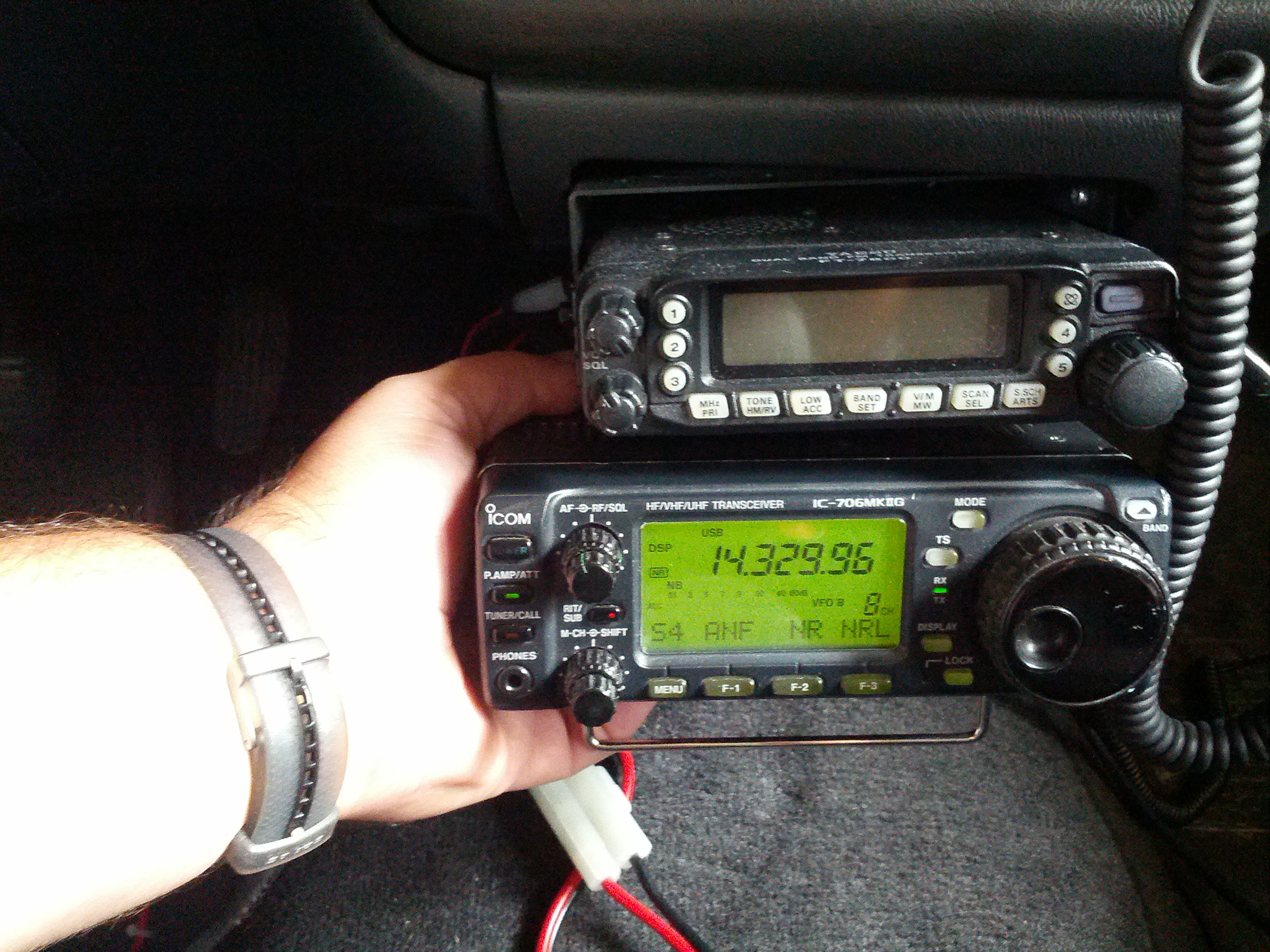
This could work.
It looks like I need to fashion a pair of brackets – one would be simple, and the other complex a little. I do have the mobile bracket for my 706, so I can always use that as a guide for holes.

It seems far simpler when it is a sketch on a post-it note than when it is a piece of sheet metal that has to fit.
Another thought with the brackets is that I don’t *have* to have the radio there. I need the head there, but I do have the head separation kit, so I can always put the radio elsewhere and run power and antenna to it.
The other thing I looked at was the antenna. Like every other self-respecting ham, I feel as if antennas should be big. I was concerned about this 20m antenna and a quick look at K0BG’s website confirmed my suspicions.
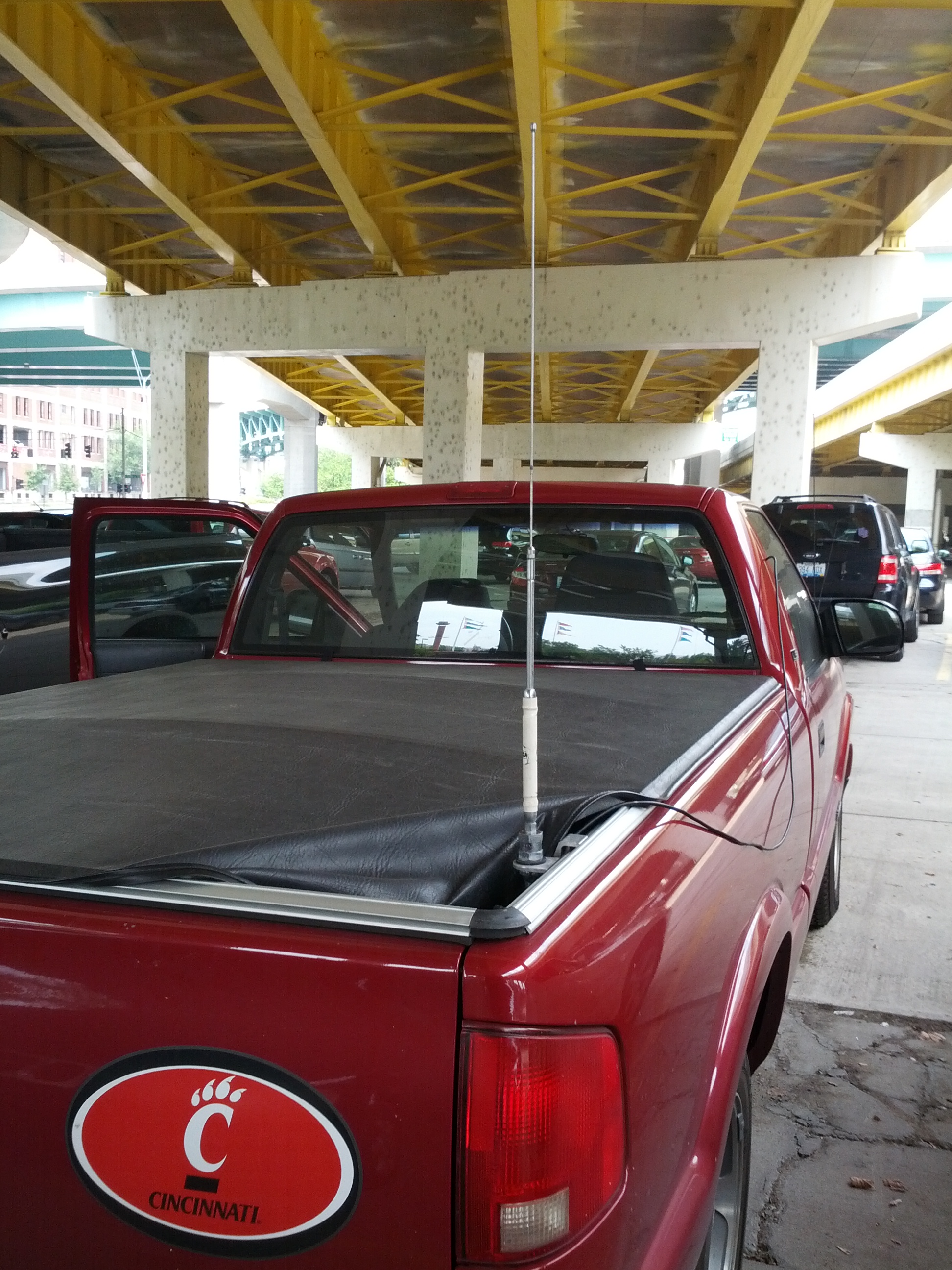
Someone gave this to me. I’m considering giving it back once I have a better alternative.
The antenna is so small compared to 5 meters (roughly a 1/4λ for 20 meters) that it has to be basically a dummy load on a stick. I’m not sure if the bridge above me helped or hurt; I had thought about driving up to Mt. Adams, but for various reasons I couldn’t stray too far. I’ll have to try again. I need to run the antenna wire (I’m not sure other vehicles would like the idea of me having that coax flapping around, and I can’t have the tonneau cover open like it is when I’m stationary.
The last consideration is power, but it isn’t a huge consideration. I have a power line that is safe for 20 amps (as much as my 706 needs), but I don’t want to have to unhook/rehook power connectors (those ARE live, after all). I’m thinking I need a miniature power distribution center with two pair of fused power poles and a master switch, and maybe a battery shutoff.
-73-
After installing my first HF attic dipole and noticing that I can hit Alaska and the Carribean really well and can’t hear New England at all, I decided I want another that is perpendicular to it (then maybe I’ll hit New England and Arizona… and Hawaii!).
I decided to do this antenna a little differently. Consider it an experiment. While I went to a lot of great lengths to put traps in my prior antenna (which shortened it’s length considerably), I decided on this one I want to try window line and see if the interference problem caused by my plasma TV is different. If not, I may be off of 40 and lower until I replace the TV with an LED TV.
Since the window line will be going down along a ventilation shaft that’s pretty large, the one concern I have is that I can’t put metal conduit in the shaft (one thing I wanted to try was to put a grounded metal conduit in the ventilation shaft and see if that fixes the interference problem).
So anyway, the pictures are below.

This is the stress reliever in the center insulator. I drilled three holes in a 3/4″ PVC coupler and used two wire ties to ensure that there isn’t too much stress on the wire joints.

This is the insulator in the center of the dipole. The long wires were soldered to the twin-lead. The PVC coupler allows for me to hang it via mason’s line.

The two sides of the dipole – wires at ~33′ each – are coiled around CLOSED coffee cans, and the window line is coiled. Everything is taped with masking tape so it can be removed easily. The cans have to be closed due the insulation in the attic – open cans would get insulation in them, closed cans do not.
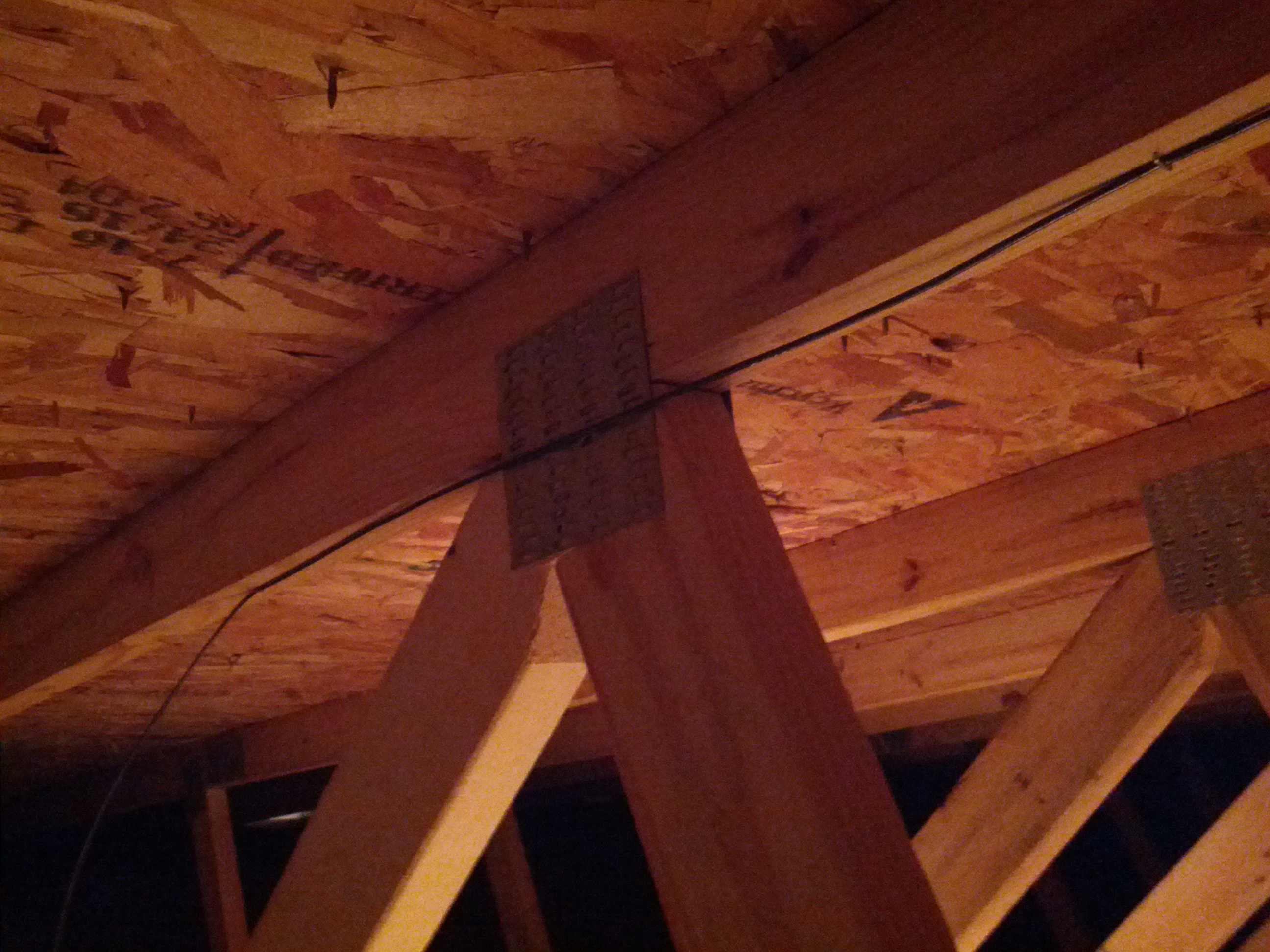
This was the only picture of the installation I could get. Let’s face it, it’s a wire in an attic, it isn’t going to be easy to see nor show anything interesting. Hope that metal plate doesn’t create a problem (there’s one on the other side too, so at least the metal plates will balance out).