
Tag Archives: oscilloscope
This still feels like yesterday’s repair, even though it was tonight when I did all this.
Since I had the final module out from yesterday, I hooked power to it to test. I first tried the driver, and it didn’t trip the circuit breaker. Then I tried the high power amp and it tripped the circuit breaker immediately. Fearing the worst, I embarked on the long process of removing the finals (which was not fun because of how they were stuffed in there.
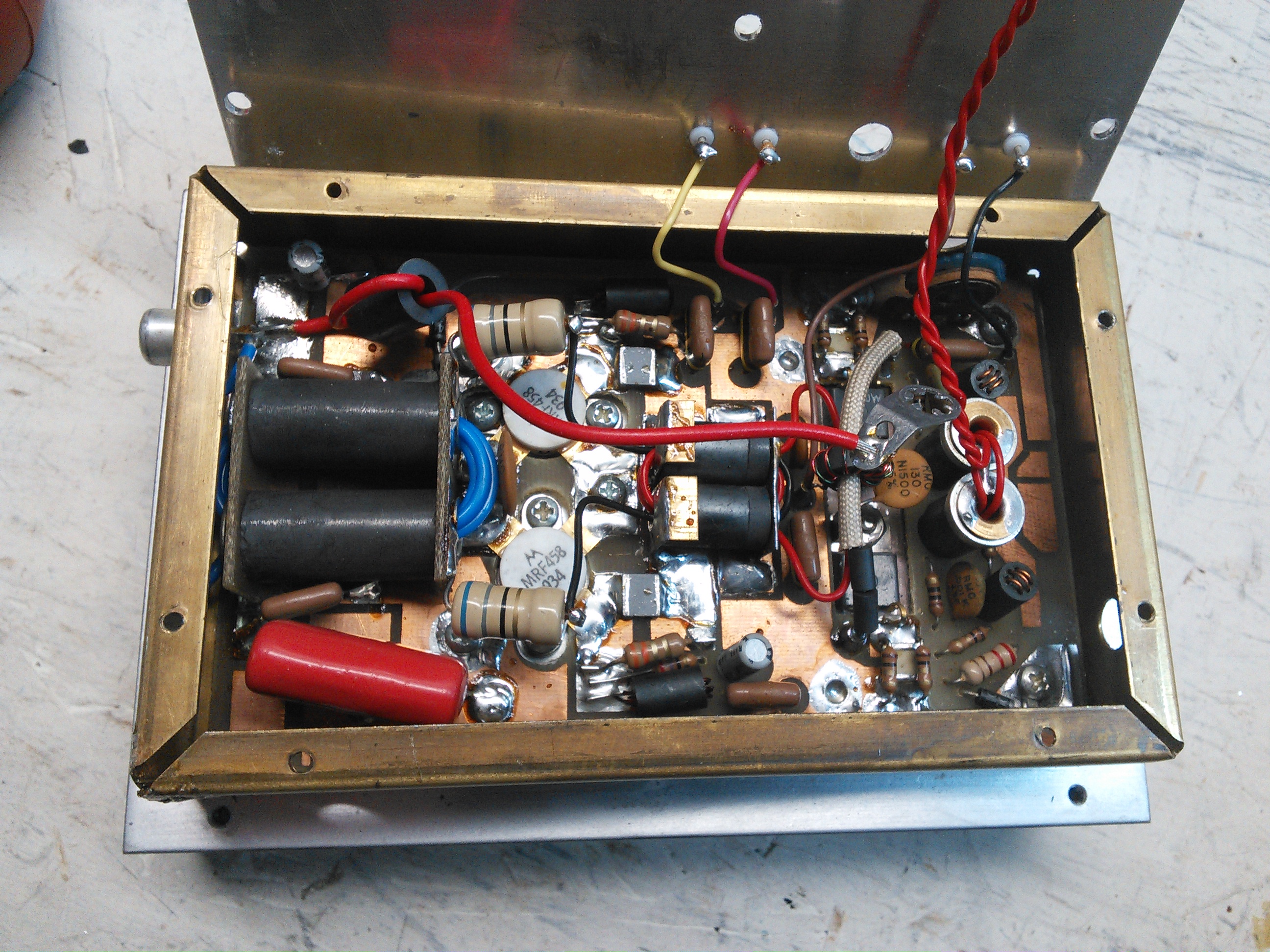
Finals in their copper case. Getting the heatsink off wasn’t too difficult, but getting the circuit board out of the copper was a pain.
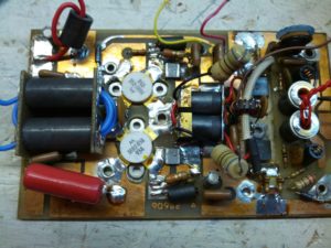
After a lot of work with a heatgun and soldering iron and wick and a bulb, I got this out.
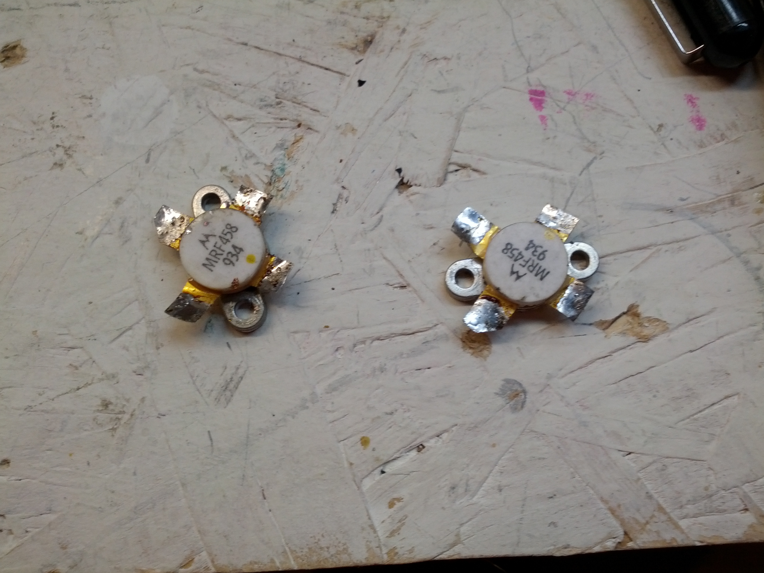
These are the finals after being removed.
So after removing these, I put them on an octopus tester, and tested them. The results are interesting. It also says that one or both of them is likely bad. These things aren’t cheap, but with how much of a pain it is to remove them, the smart thing would be to replace both, since one went, the other is likely not far behind.
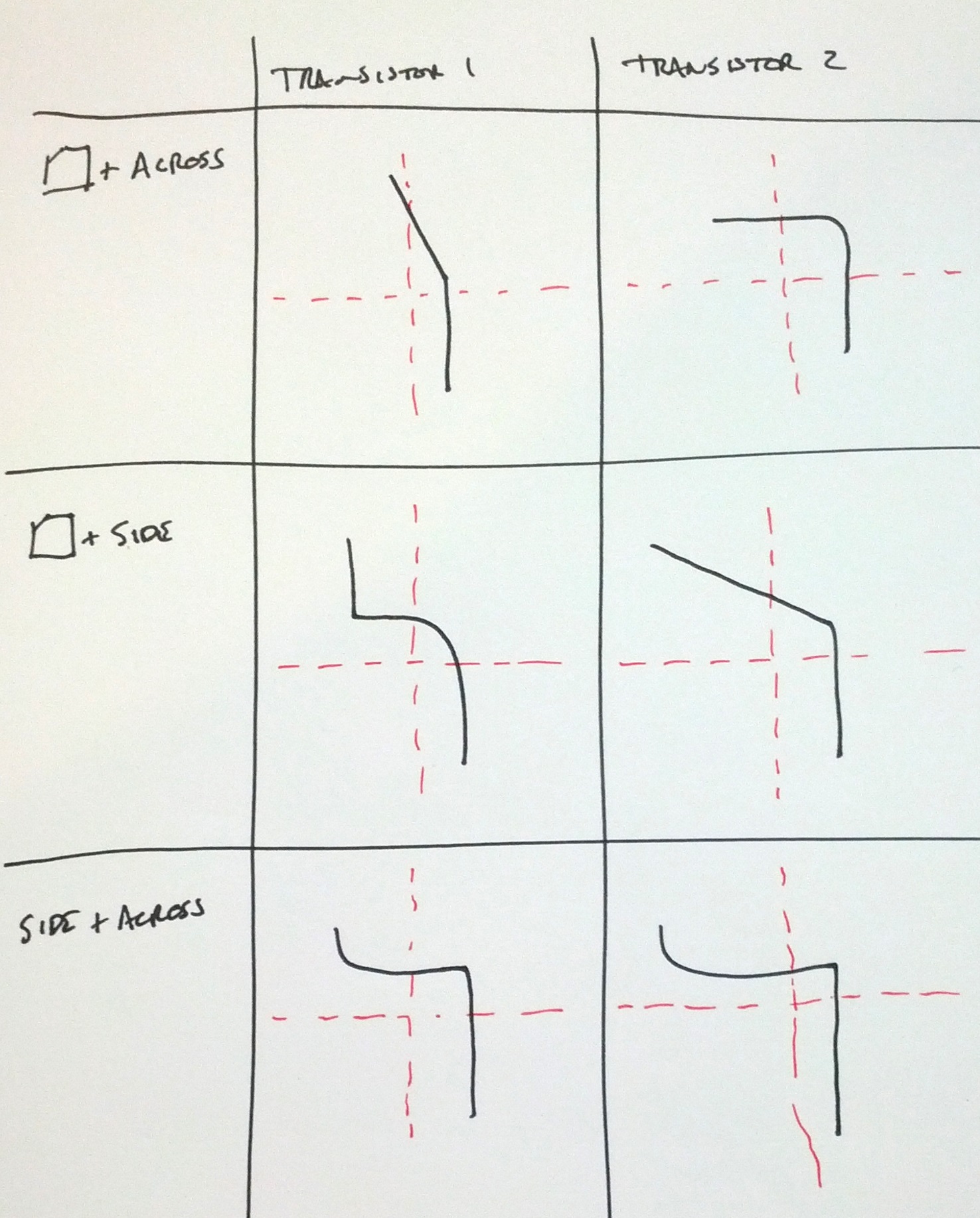
Note: the upper-left and middle-right are nowhere near the same:
Upper Left
Middle right
Next up: replacing the transistors and powering the unit back on!
-73-
Since I’m not an electrical engineer and they teach nothing about oscilloscopes in traffic engineering classes, I’ve been viewing lots of videos about using scopes on YouTube. After seeing W2AEW’s video, I thought I’d get an Arduino and make a “poor man’s TDR” (as he calls it) by having the Arduino output pulses.
This is really quite simple. Too simple.
So simple it didn’t work.
Initially, it looked pretty good. I don’t know about the accuracy of the Arduino, but I imagine that it is good enough. The problem, I’m guessing, is the current. An Arduino is pretty limited (40 mA), so pushing it through a cable and expecting it to be able to act like the video might be pushing it.
Anyway, for the sake of showing, here’s what I did…
The Arduino Sketch
The Circuit

It’s pretty simple. Plug the scope probe into pin #7 and ground the scope probe ground to the Arduino.
The Results
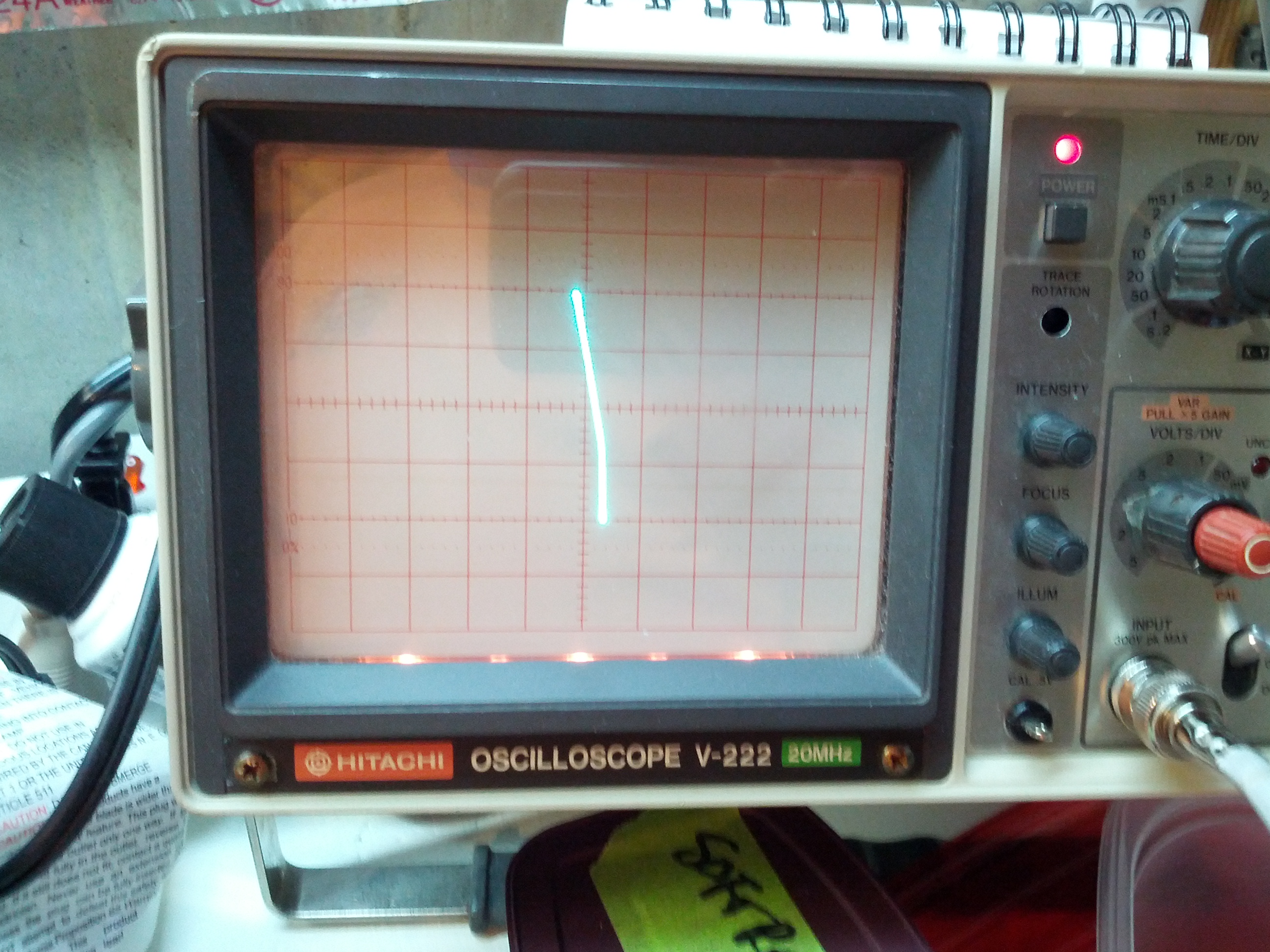
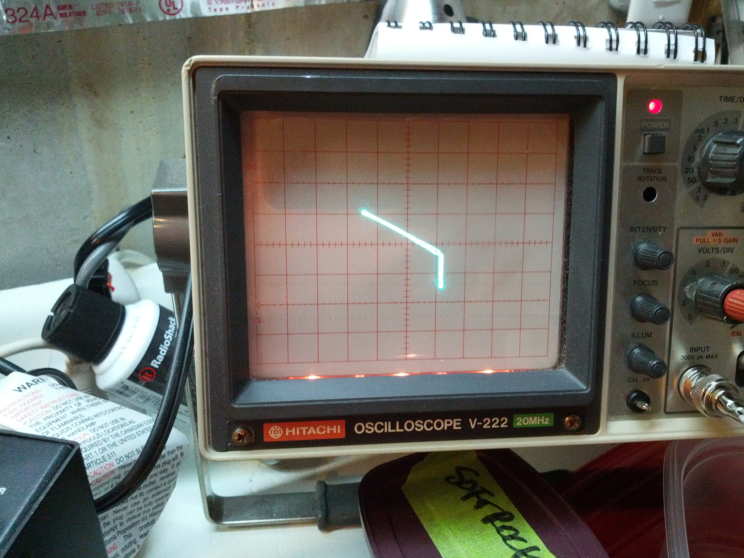
Without any coax or with a ~6 foot piece of RG-58 open at the other end, I can see the step from the pulse. But when I connect a 50-ohm dummy load, the voltage drops.
Without a load:

With a load:

Note the difference in voltage between the two. I had the scope set to DC for these to keep the baseline the same, and the voltage per division was 1V.
Back to the drawing board.
-73-
This post is about the recently-built and the to-be-built projects I’ve been working on.
Recently Built: RF Sampler
First off, the recently-built. I recently built an RF Sampler. This little device allows me to connect a rig under test to my oscilloscope. The schematic is quite simple, as it is basically a voltage divider that divides the voltage between an internal resistor and a dummy load. Below are the pictures.
And what are pictures without a video to show it works?
The schematic for this is at http://www.qsl.net/k6ls/rfsampler.html. Also note this video from W2AEW (which is an expanded design of this).
Recently Built: Octopus Tester
Another item I recently built is an octopus component tester. This is a simple tester that makes some basic tests on electrical components, like capacitors. You can’t get the value of capacitance (etc) from this, but you can see if it works by hooking it up to the tester and checking it on an oscilloscope. I built this into an Altoids tin.

Below is what a capacitor looks like on the scope.

More information on this can be seen on W2AEW’s video.
In The Pipeline
I have one item in the pipeline, maybe two.
One of them is a Time Domain Reflectometer. There are schematics for that in the ARRL Handbook. This would help me test coax. I may jump to an Arduino-based pulse generator first.
-73-
So I spent my disposable part of the day building an RF Sampler and looking at the oscilloscope. At first I kinda got worried. I saw the image below.

So then I realized that at 20mV per division (you can’t see the pointer in the image, but it IS on 20 mV), that’s not so terrible. Especially when I look at the video below:
This was on 1V per division. So that looks okay I guess. Initially I was concerned about the distortion I was hearing on my wideband HT, but since my HT was on AM (no SSB modes available), it is probably okay.
So I’m on to looking at the antenna and feedline. Next up to build: a field strength meter.
-73-