
Tag Archives: pcb
My work has taken me down the road of using Raspberry Pis as data collection devices. This means I need to power a Raspberry Pi in the field. I’ve had trouble finding a reasonably-priced 12V to 5V USB adapter that I could easily and safely fit into a box with a RPi. So I designed one in KiCAD and built it. The design is on my work github account.
I’m ultimately designing something that will connect to a battery, and batteries can explode if mistreated. Testing is critical, as is circuit protection (the fuse). I’m envisioning this to be in a box on the top of a pole with a camera, so the lead going from the battery (which will likely be on the ground) will be fused in case the wire gets cut. This is critical for the same reason it is necessary in a car – to protect the battery from short circuiting should something happen.
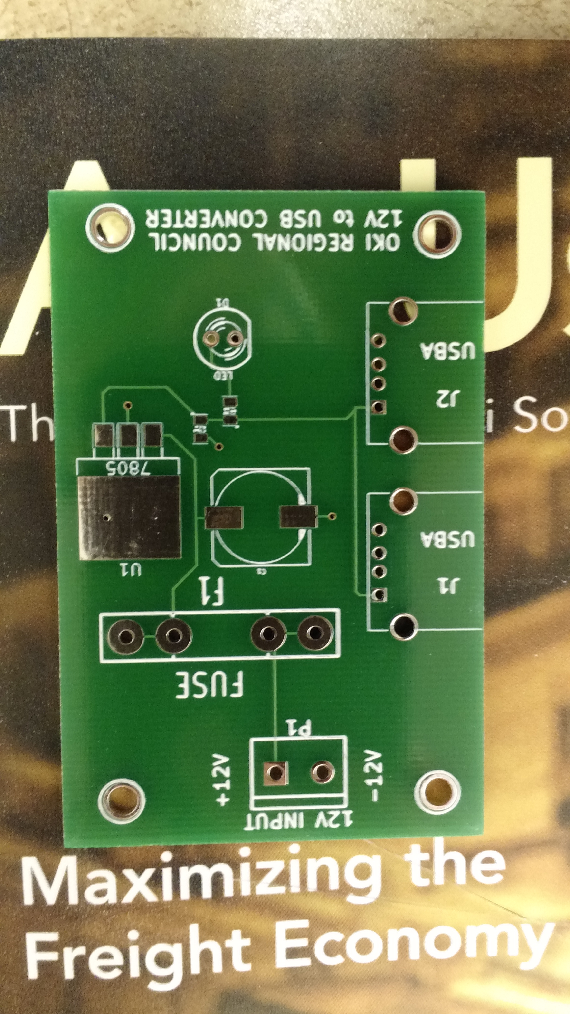
Empty PCB
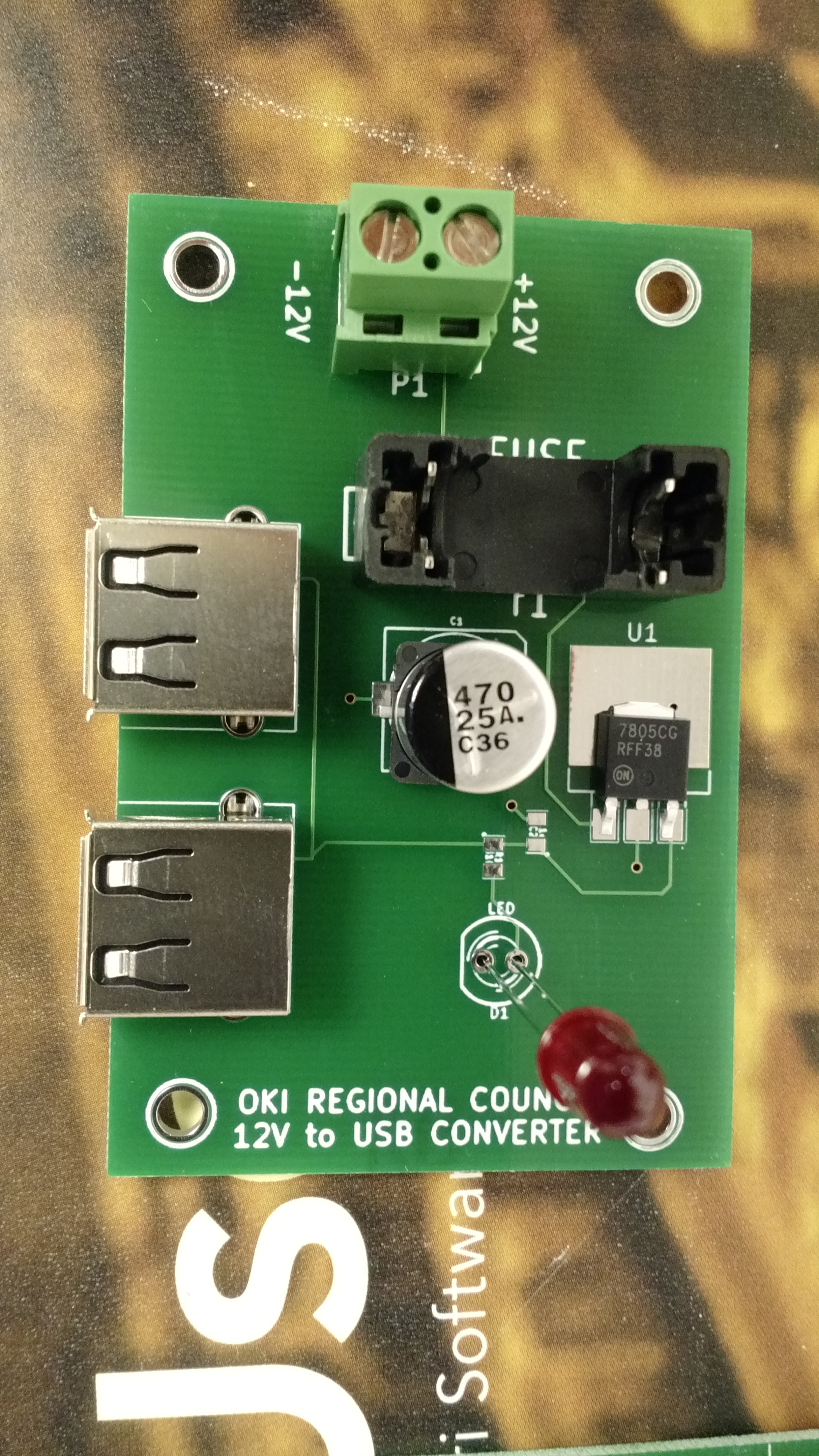
Test fit components at the office.
In putting these together at home, I tested these in every way I could think of, and assembly and testing went something like this:
- Solder SMD C2 and R1
- Test resistance from 7805 output to LED positive solder hole, should be 330 ohm (I used 330 ohm resistors instead of 310, since I don’t happen to have any 310 ohm).
- Test continuity from 7805 output to ground via connected to C2. Should show no continuity.
- Solder USB connectors and C1
- Test capacitance from 7805 input to to ground via near C1. Should show a reading (mine all showed around 1000 uF, which is high, but my understanding is that multimeters are notoriously bad at capacitance)
- Add input headers, fuse holder, and LED
- Test continuity between inputs – should immediately beep, and then drop to no continuity after capacitors charge
- Apply voltage, LED should light, all magic smoke should remain contained in devices
- Test voltage from 12V- to 7805 output – should be 5.0v (mine showed something like 5.007v)
The one thing I was unable to test was the actual USB output voltages, but it seems to me that they should be okay.
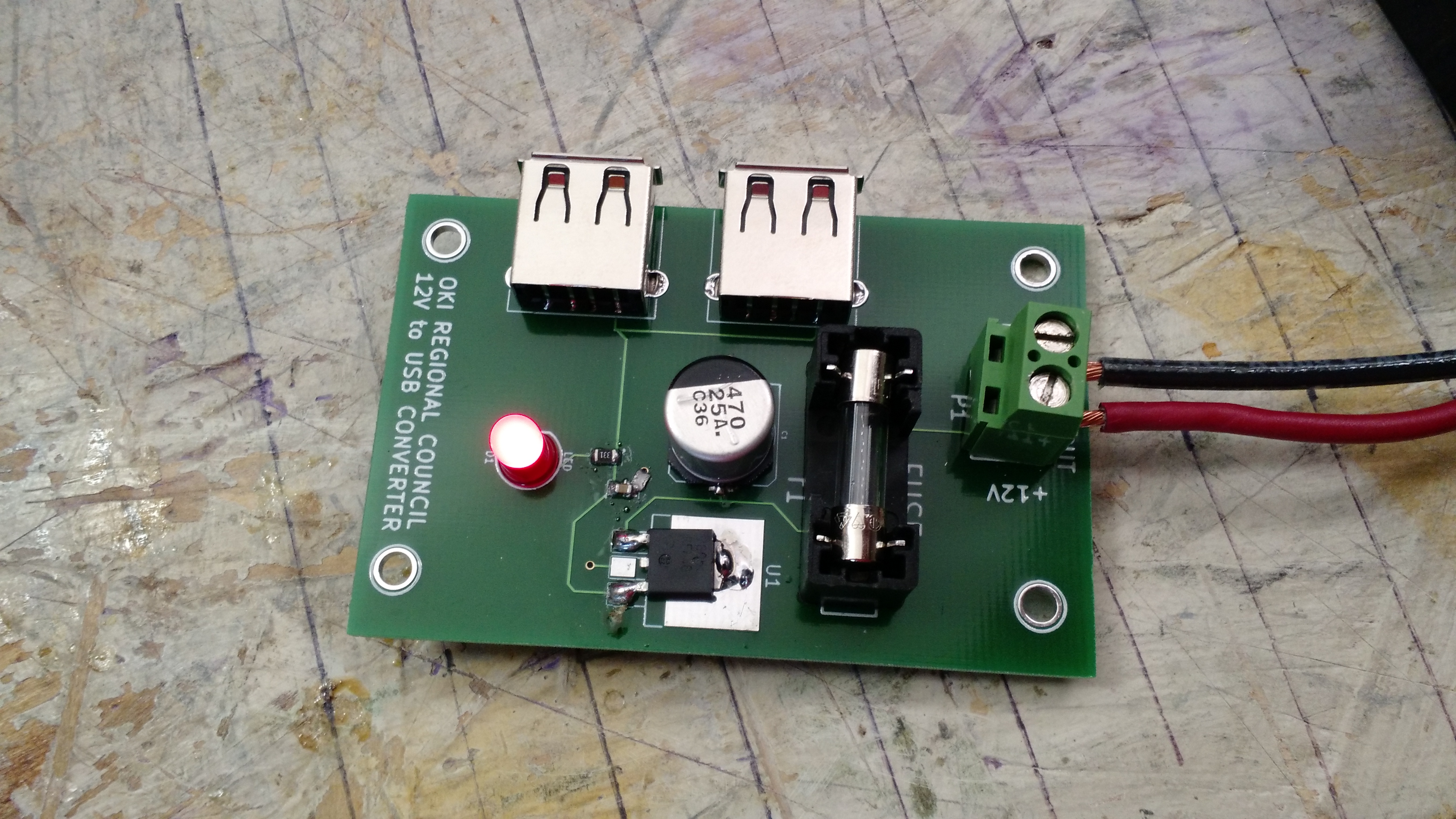
IT LIVES!!! This is one of 5 I built.
I have five blank PCBs left for additional builds should I need it, although I’d have to have work buy more components. Maybe I could get some larger 7805s that would fit the ground pad…
-73-
I’ve had a sudden want and need to print a few PCBs. I’m not going to re-hash the toner transfer method that everyone else has documented, but I will note three things that I’ve learned:
- Sanding the PCB with 600 grit sandpaper and cleaning with denatured alcohol is a must (you could probably use acetone or isopropyl alcohol too, the idea is to get any oil or dirt off the copper
- HP Banner and Flyer paper works fine for this. That may be documented somewhere, but everything I see says to use a photocopier and manually feeding magazines through it. I’m using my own laser printer, so the idea of feeding magazine pages through it is a bad idea to me… now, if I was using a copier at the library or drugstore or gas station, I would have no reservations.
- This method is never perfect. Never.
- Drilling sucks. Design for SMT, if you can.
I’m working on several things, including a small guitar amplifier and an upconverter for my RTL-SDR. The upconverter is one where the PCB layout was supplied and I printed it. I put it on larger PCB than it called for, hence the crappy looking surround.
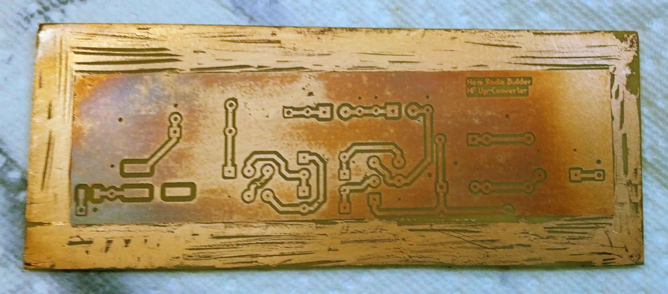
There’s some discoloration too, but that doesn’t seem to be an issue.
Prior to this, I did print two other PCBs. These were designs I did in Eagle. Both look like the PIC16 below (okay, the other, a real-time clock, was larger!). In both cases, these are just breakouts so I can use them with a breadboard. I forgot that I have a set of small drill bits somewhere.
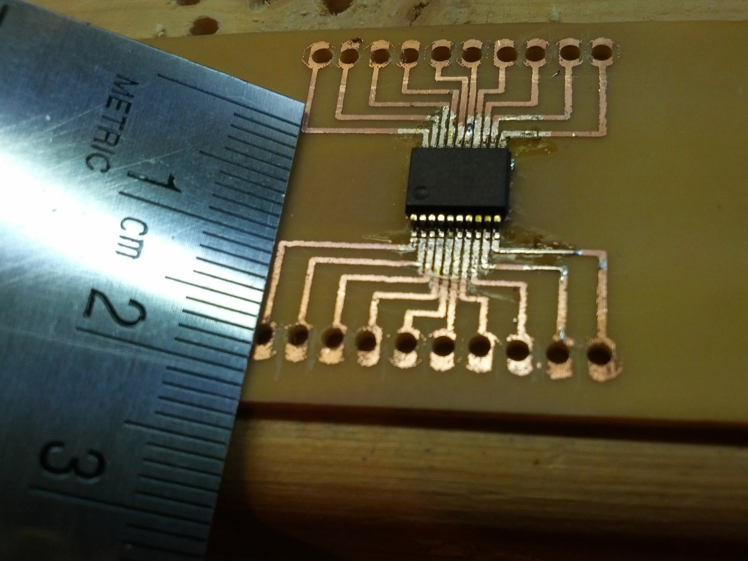
Yeah, this PIC16 is dinky!
Moving forward, I will be using both the software and techniques used by Contextual Electronics as noted on this page on kohanbash.com. The videos are EXTREMELY HELPFUL! I may still print prototypes at home, but with all reality, I may just print the layout on normal paper and set the parts on the paper to fit them and then send the PCB off to a service.
A side note on printing these things at home. Rocking trays full of dangerous chemicals for long periods of time is only fun when you’re developing photos, and that ship has sailed (with my film camera, developing tanks, dark bag, and bulk film loader on the boat). If I do this a lot, I may end up building something that rocks the tray, as it would be pretty simple to build.
-73-