
Tag Archives: power supply
My work has taken me down the road of using Raspberry Pis as data collection devices. This means I need to power a Raspberry Pi in the field. I’ve had trouble finding a reasonably-priced 12V to 5V USB adapter that I could easily and safely fit into a box with a RPi. So I designed one in KiCAD and built it. The design is on my work github account.
I’m ultimately designing something that will connect to a battery, and batteries can explode if mistreated. Testing is critical, as is circuit protection (the fuse). I’m envisioning this to be in a box on the top of a pole with a camera, so the lead going from the battery (which will likely be on the ground) will be fused in case the wire gets cut. This is critical for the same reason it is necessary in a car – to protect the battery from short circuiting should something happen.
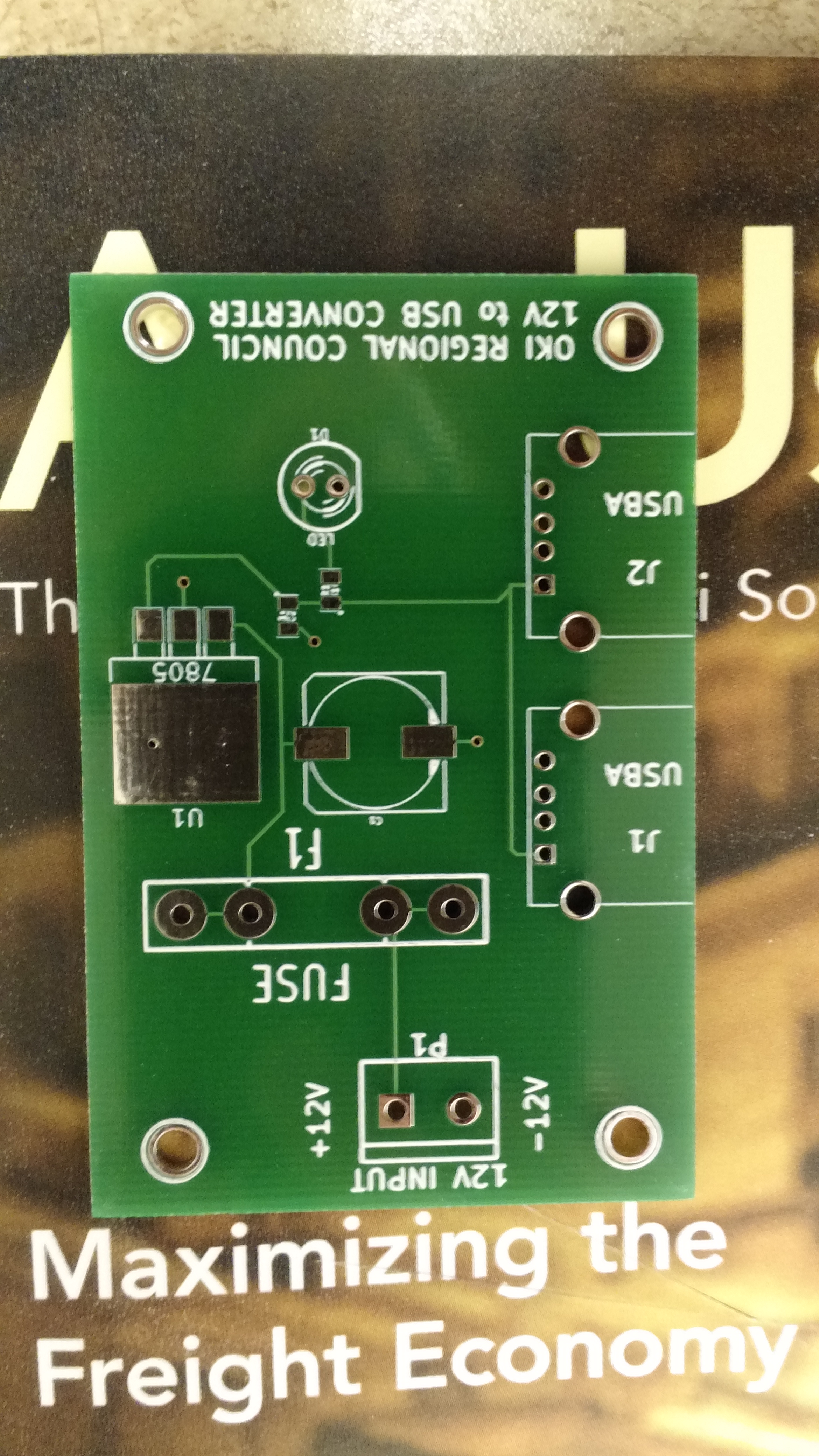
Empty PCB
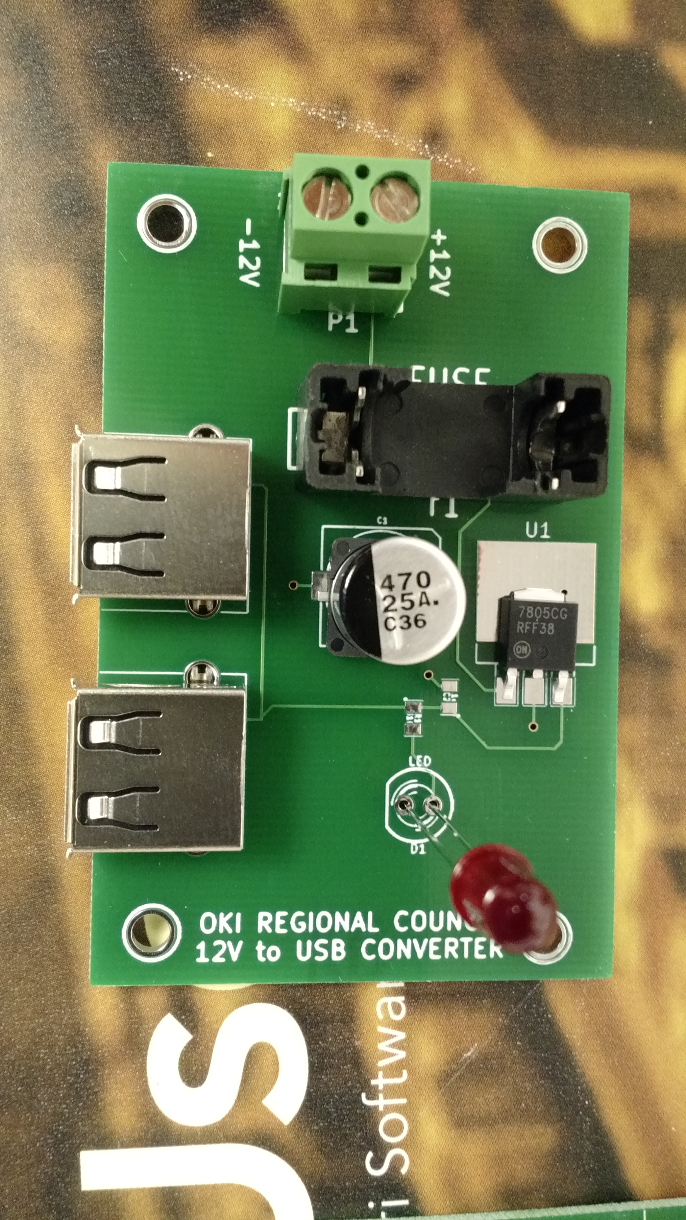
Test fit components at the office.
In putting these together at home, I tested these in every way I could think of, and assembly and testing went something like this:
- Solder SMD C2 and R1
- Test resistance from 7805 output to LED positive solder hole, should be 330 ohm (I used 330 ohm resistors instead of 310, since I don’t happen to have any 310 ohm).
- Test continuity from 7805 output to ground via connected to C2. Should show no continuity.
- Solder USB connectors and C1
- Test capacitance from 7805 input to to ground via near C1. Should show a reading (mine all showed around 1000 uF, which is high, but my understanding is that multimeters are notoriously bad at capacitance)
- Add input headers, fuse holder, and LED
- Test continuity between inputs – should immediately beep, and then drop to no continuity after capacitors charge
- Apply voltage, LED should light, all magic smoke should remain contained in devices
- Test voltage from 12V- to 7805 output – should be 5.0v (mine showed something like 5.007v)
The one thing I was unable to test was the actual USB output voltages, but it seems to me that they should be okay.
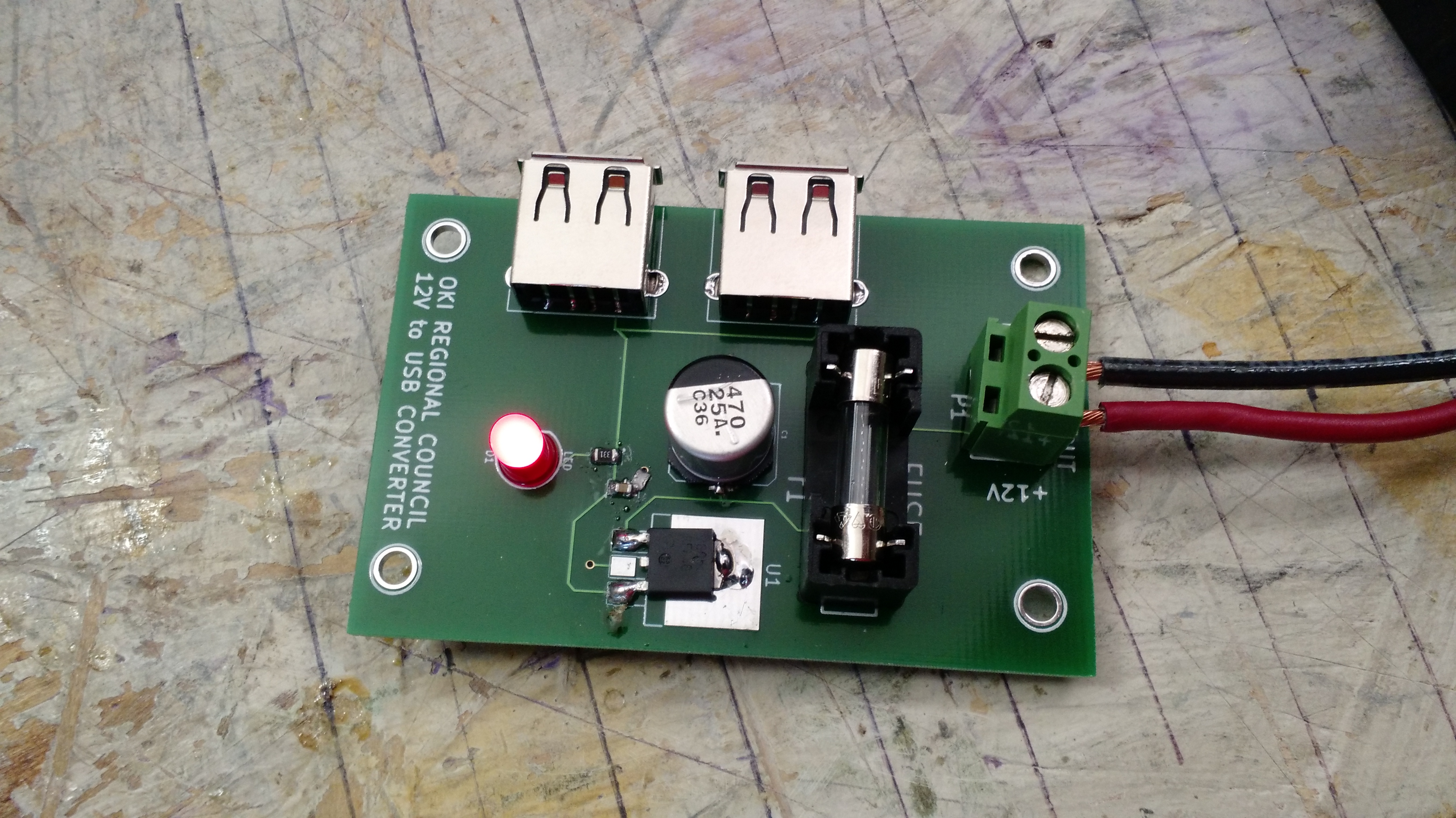
IT LIVES!!! This is one of 5 I built.
I have five blank PCBs left for additional builds should I need it, although I’d have to have work buy more components. Maybe I could get some larger 7805s that would fit the ground pad…
-73-
This is a post of semi-random electronic carnage.
This is some plastic that went between the metal case and the circuit board. The two things sitting on it are capacitors. It appears they went off like bottle rockets.
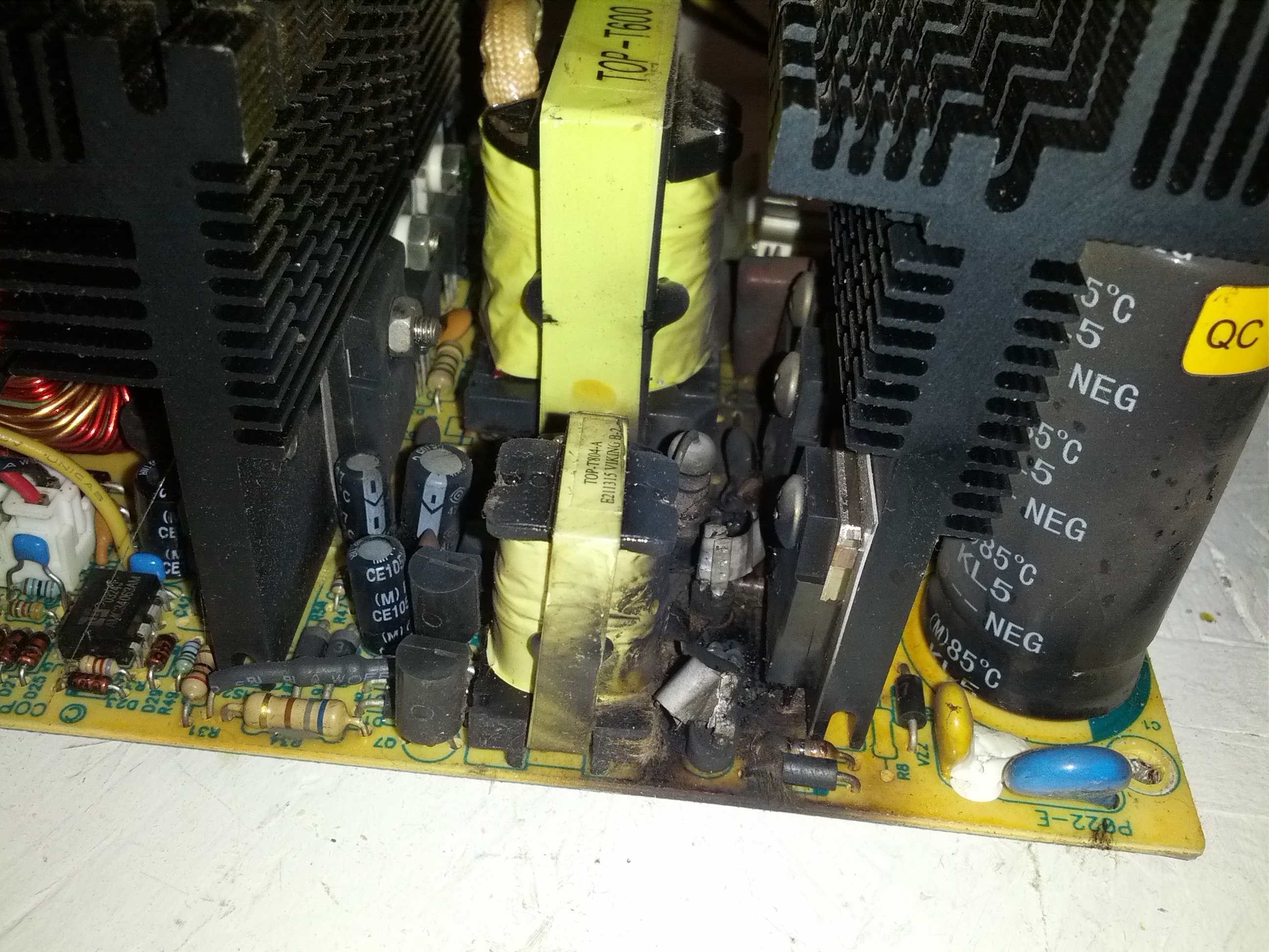
The high-voltage area of the power supply. This is where the failure occurred. Note the charring.
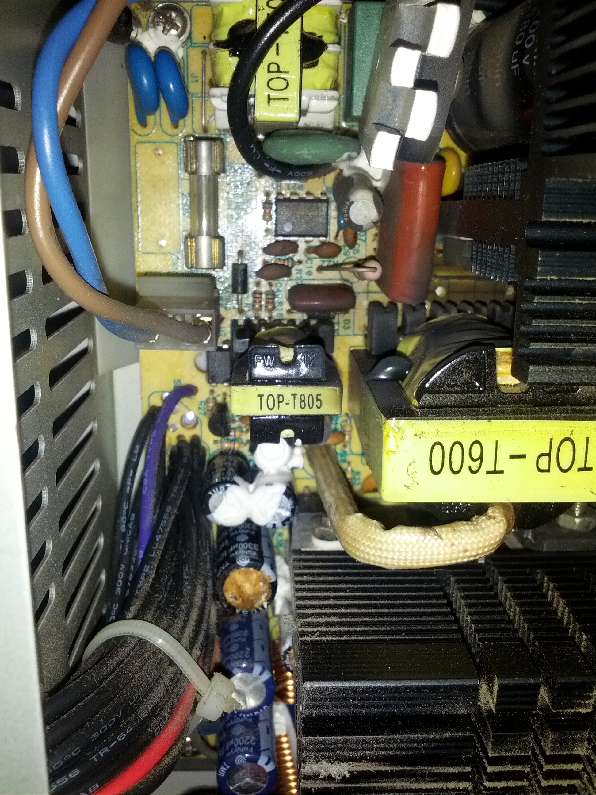
This is the top of the power supply. Some of the caps are definitely exploded.
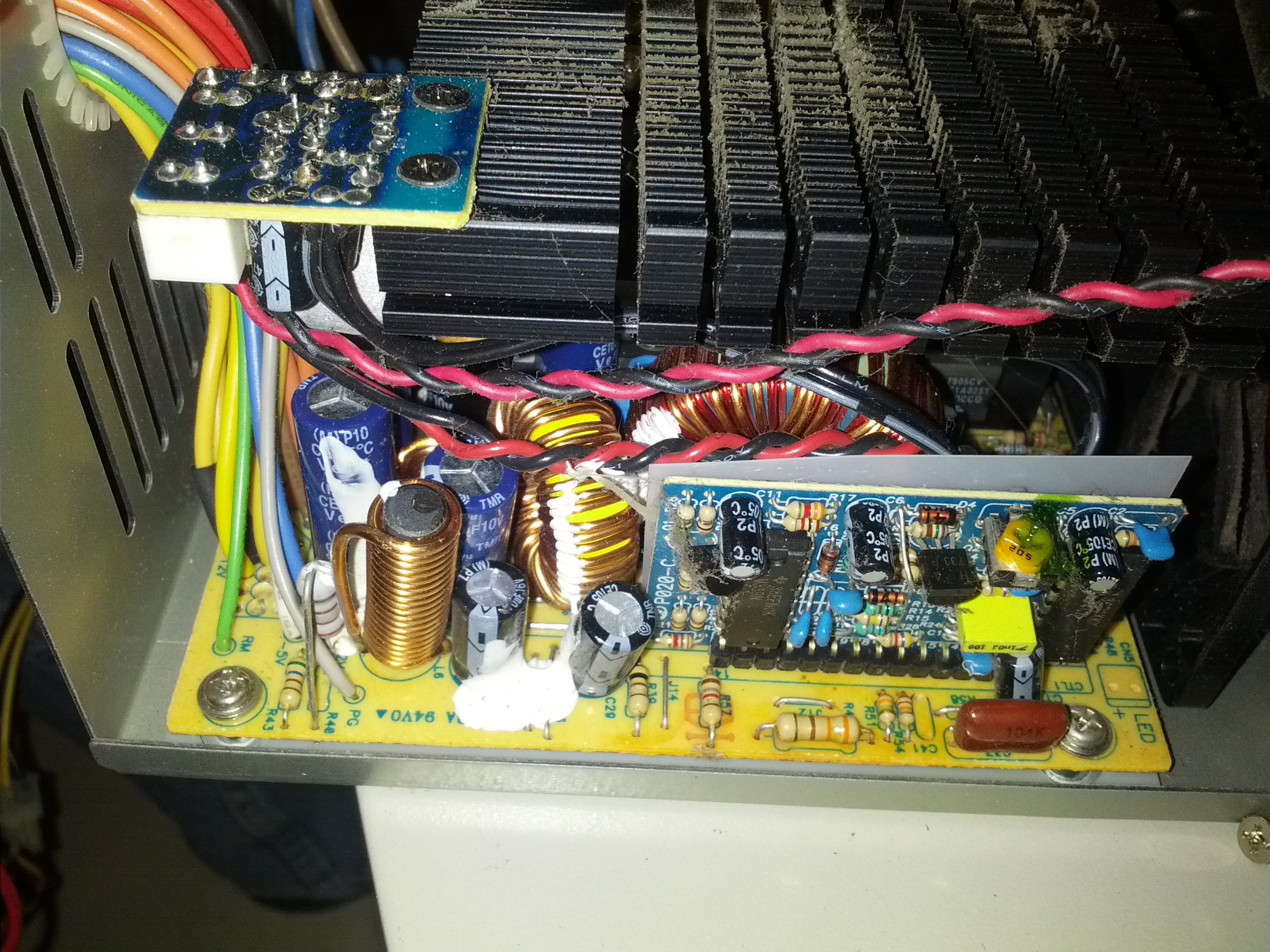
This is the low voltage area of the power supply. There isn’t much visible damage here.
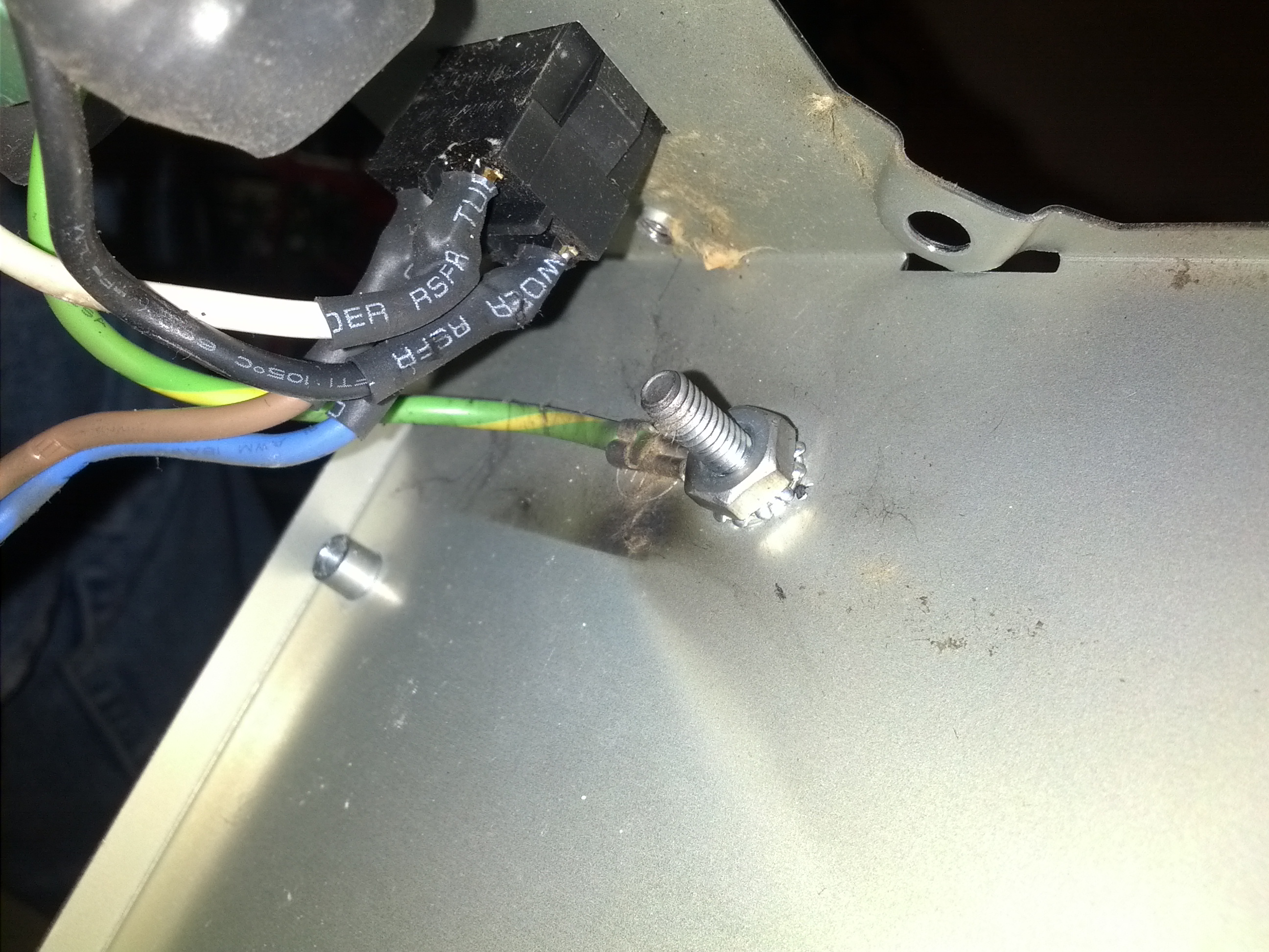
This is the grounding bolt. Note the burn marks.
-73-
Last summer, a friend brought me an Astron RS-35 Power Supply to repair. It had been involved in a near-lightning-strike experience that fried the loading coil on an antenna, among other things. The problem was that as soon as the supply was switched on, it would blow the fuse. The only thing that was obvious was that something was causing the SCR crowbar circuit to fire and blow the fuse to save the power supply.
I started out by checking the bridge diodes and filter capacitors. All seemed fine. I checked the pass transistors and those were fine. During a last resort, I removed an electrolytic capacitor and replaced it with another of the same value, but less voltage. My hope was that the voltage on the original capacitor was unnecessary, or that I would have enough time to test a few things before it blew.
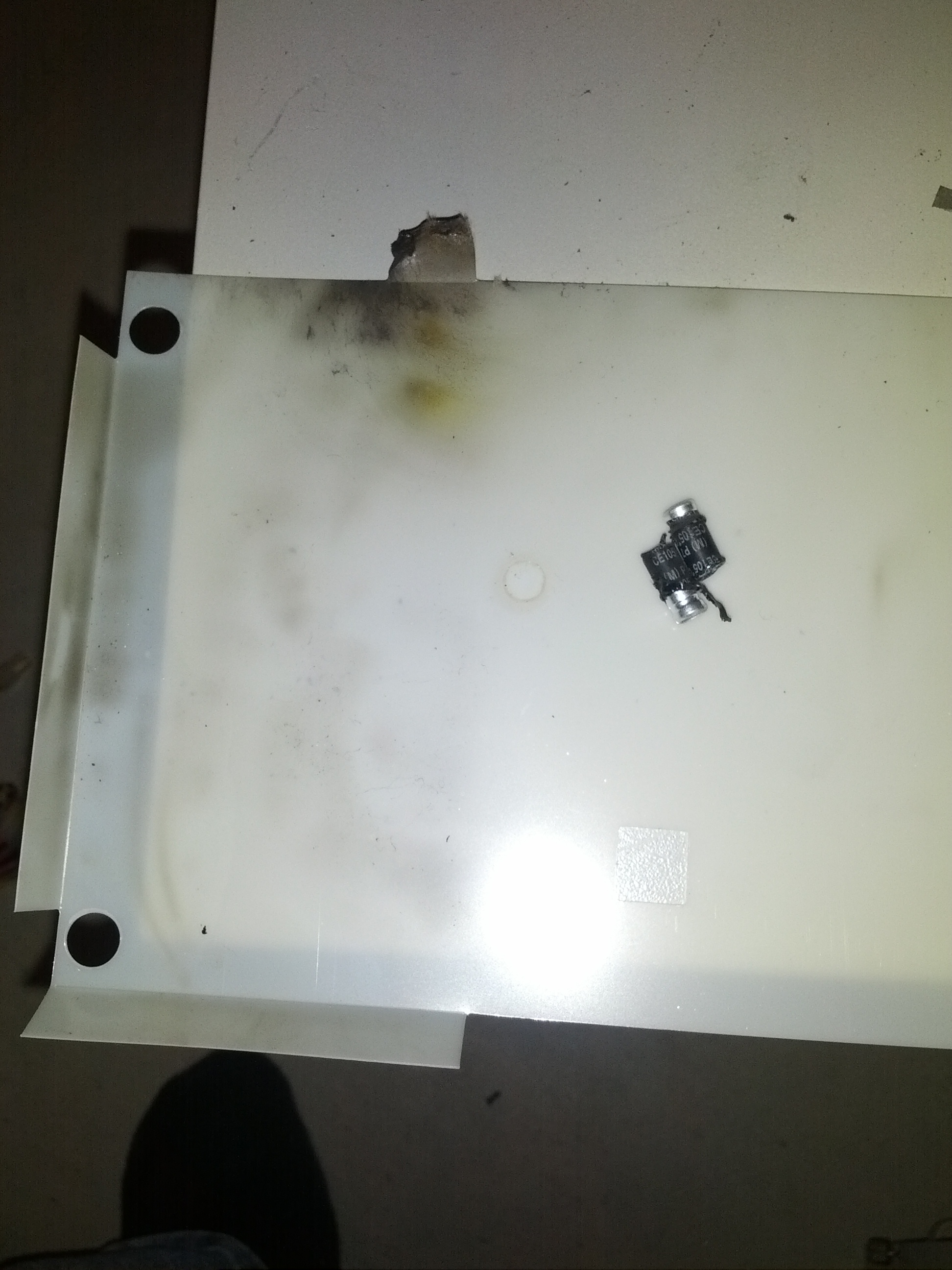
Of course, it never happens that way. I had about 15 seconds (not enough time) before letting the magic smoke out of the capacitor. So, since I’m not an electrical engineer, I decided to run a few tests on the blown cap. I noticed that there was no physical damage to the capacitor EXCEPT a small hole in the jacket.
So after staring a little at the schematic (there is an awesome resource on the Repeater Builder website), I decided to remove a capacitor (C6 on the schematic image below). It seemed like a likely possibility, since this was part of the SCR firing circuit (the part I circled in orange highlighter).

Low and behold, it was it! I replaced the part with a new one, and the power supply is done!
-73-