
Tag Archives: repair
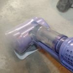
WifE8P was complaining that her Shark Steam mop was not producing a lot of steam. That’s really the only way we clean the dining room, kitchen, and entry floors, so it’s pretty important for it to work.
The steam would act like it was operating, but would put out little steam.
-
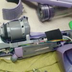
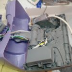
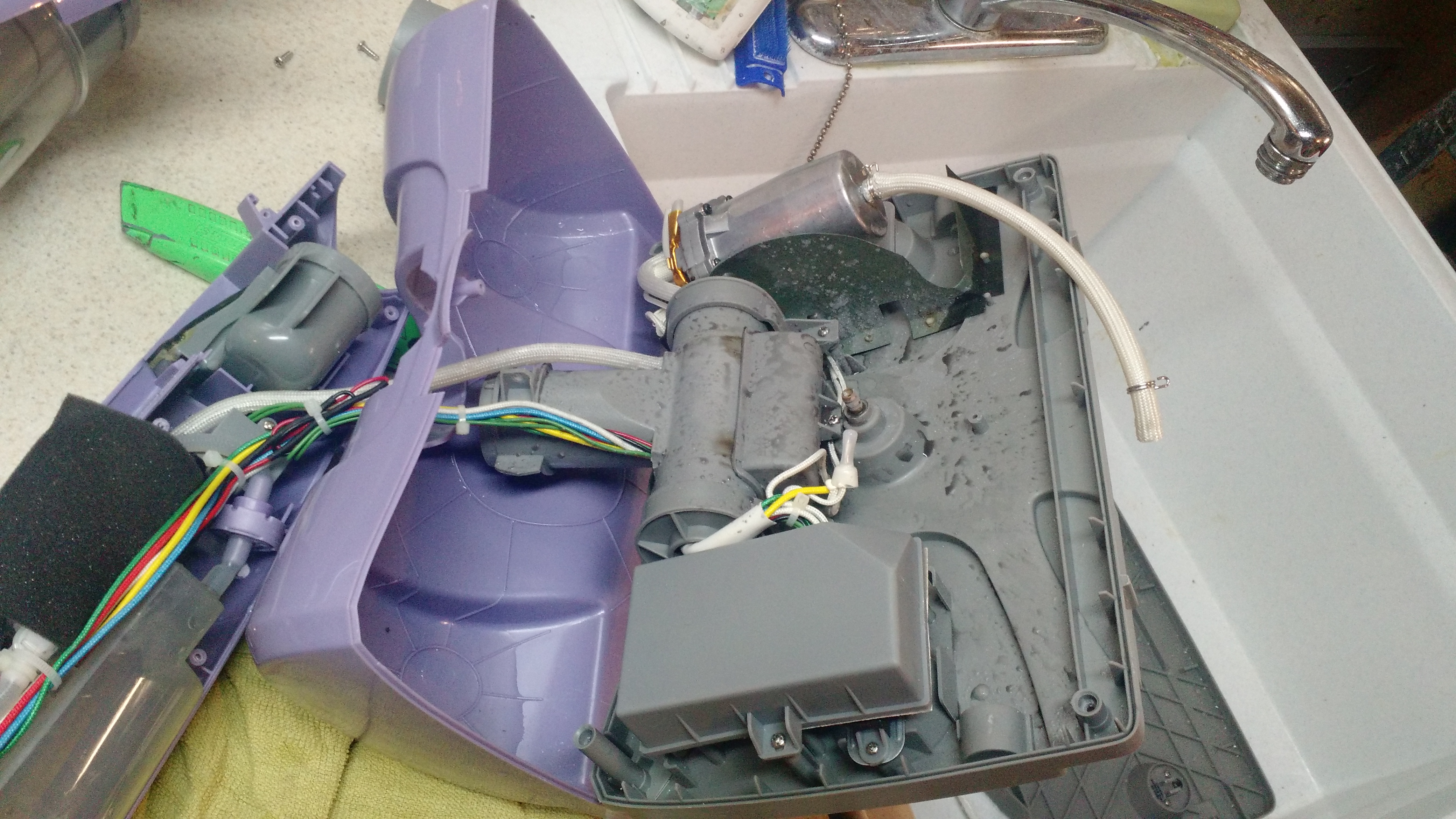
- This is actually pretty easy to take apart. The only tool required is a Philips screwdriver, and there are few clips.
-
- This is the pump. During troubleshooting, the pump DID (and still does) work. The fact that it was operating and nothing was coming out means that it was pressurizing the hose going from the pump to the mop head nozzle.
-
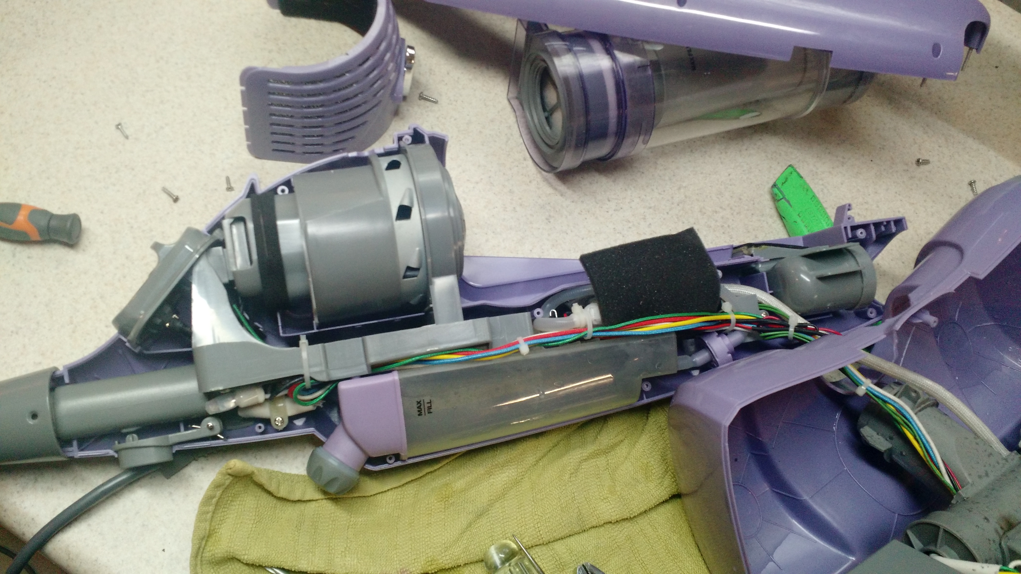
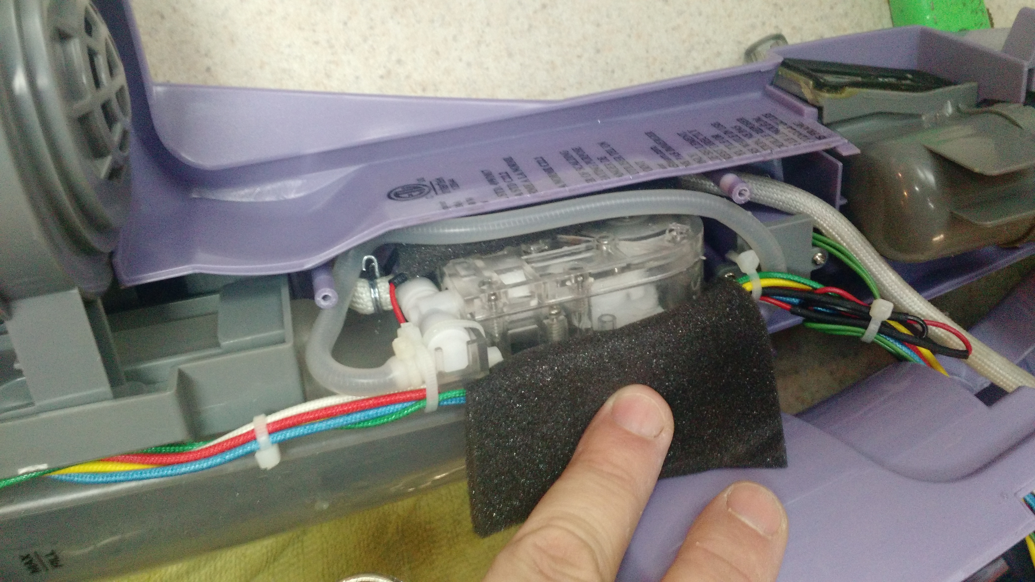
- This is the inside of the sweeper/mop end after removing the steam hose from the outlet. DANGER: STEAM. HOT. I was lucky it fired AWAY from me!
-
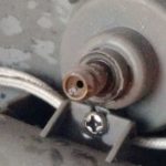
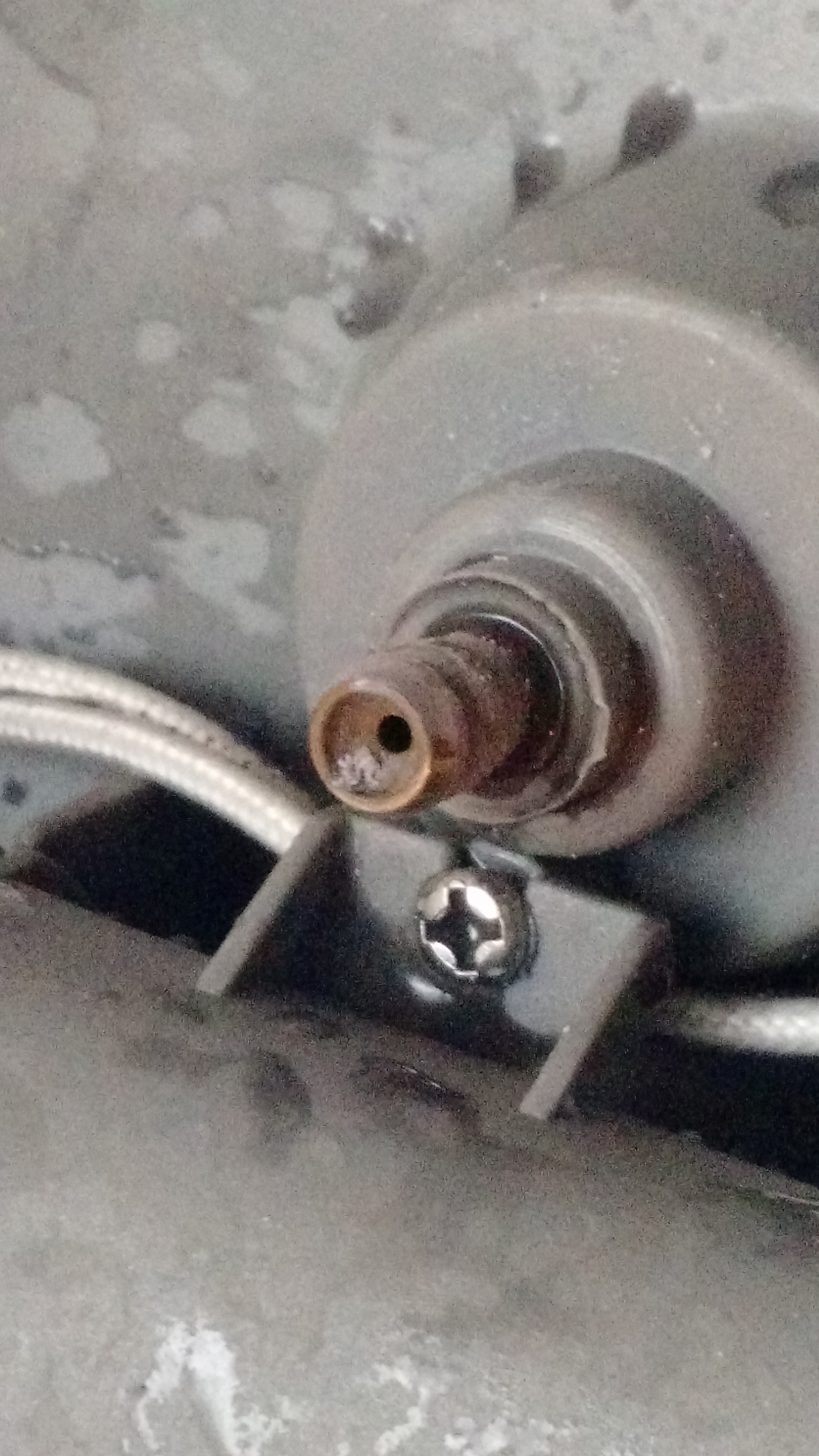
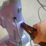
- This was the problem – a pebble made it up to the outlet nozzle.
-
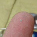
- This is the pebble.
-
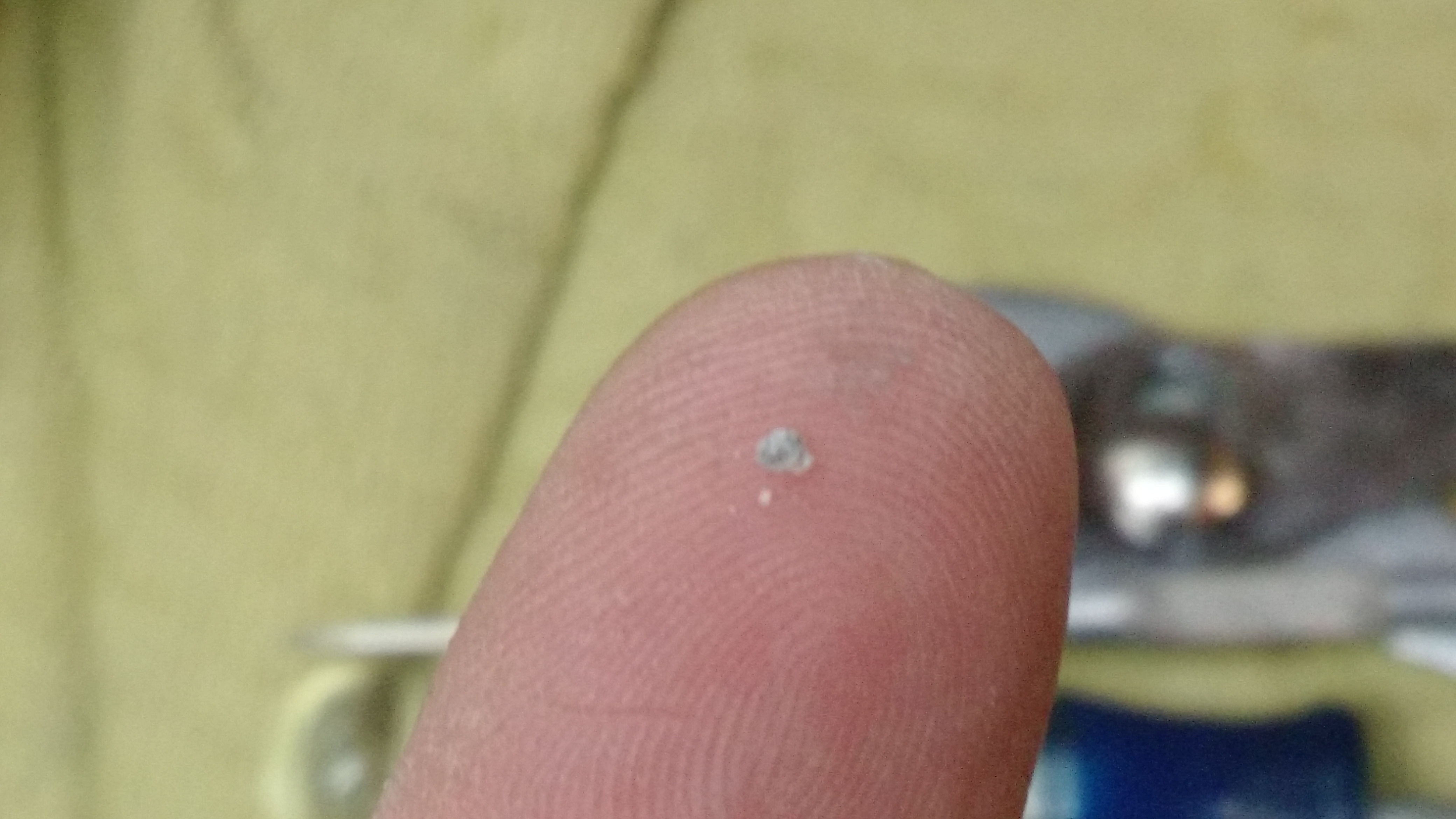
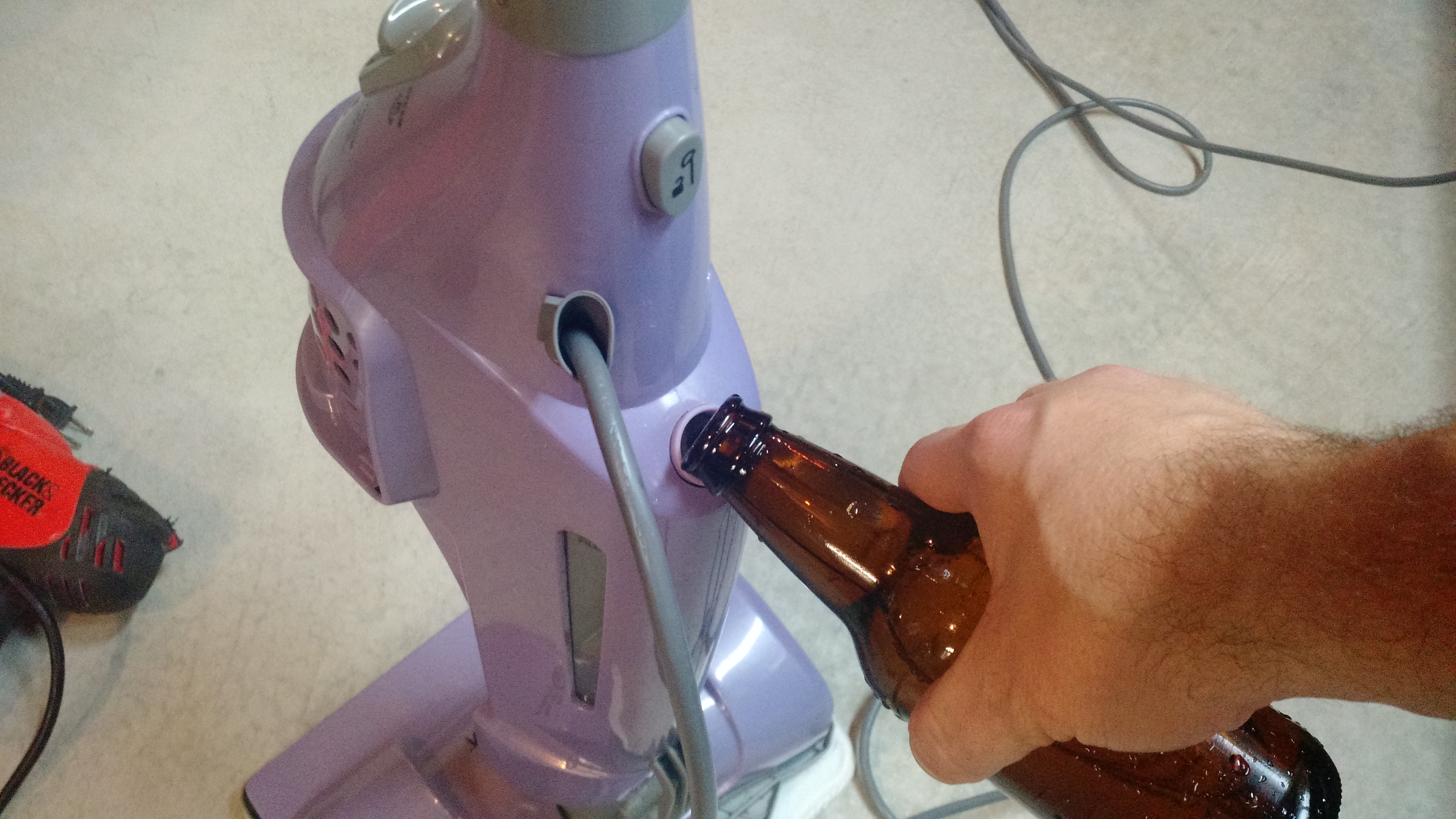
- Filling to test.
-
- It works!
-73-
For anyone on the Amateur Repairs (*cough* yahoo *cough*) group or who follows me on G+, YouTube, or Twitter, you’ve likely seen posts related to my IC-706 mkIIG. I’ve pulled the radio out of service because of problems primarily on VHF-FM (at least it seems that’s where the problems are at). In fact, since early December, I’ve been sporadic with transmitting with it, and I haven’t transmitted with it at all since mid-January.
The problem I’m having is extreme static even with very strong signals. I’ve checked the likely (hopeful?) culprits of power cords and antenna connections. Since things seem to be fine on those – I’ve tried two power cords and three power sources and two different antenna setups – I’ve moved on to checking internals.
My first check was for anything obvious. Like this, this, or even this. Nothing. I don’t know if I should say “fortunately” or “unfortunately”.
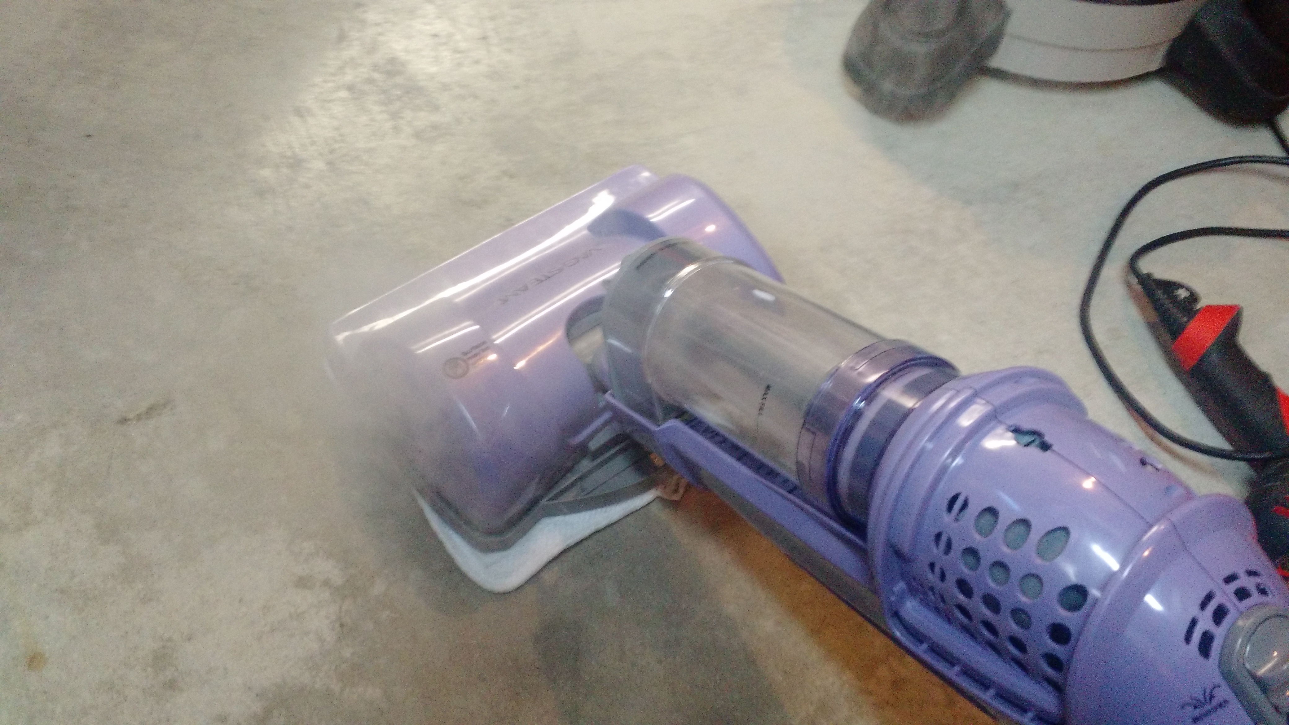
My second check was to poke around inside. I first looked at some of the audio waveforms at the NB test point and the WFM test point. Pretty interesting to see on a scope, and they didn’t react to volume (that’s a good thing, as this is likely before the audio amp!).
The Noise Blanker Test Point
(PS in the video above: yes, I’m checking that with an oscilloscope probe. It works, even if it isn’t necessarily ‘right’… or maybe it is, I don’t know).
My second test was to do something more … practical. I know from some of the reading I’ve done in the ARRL Handbook, the owners and service manual for the rig, a video from Kenneth Finnegan (from The Life of Kenneth blog that I follow), and some comments from Mike M. on Google+ that maybe I should check the PLL board. And besides, checking stuff is easy, right?
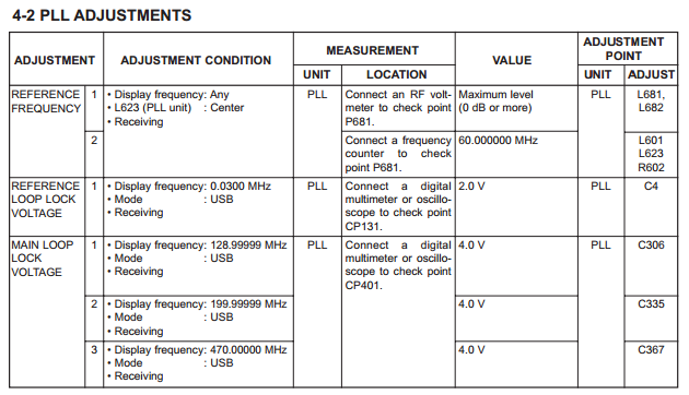
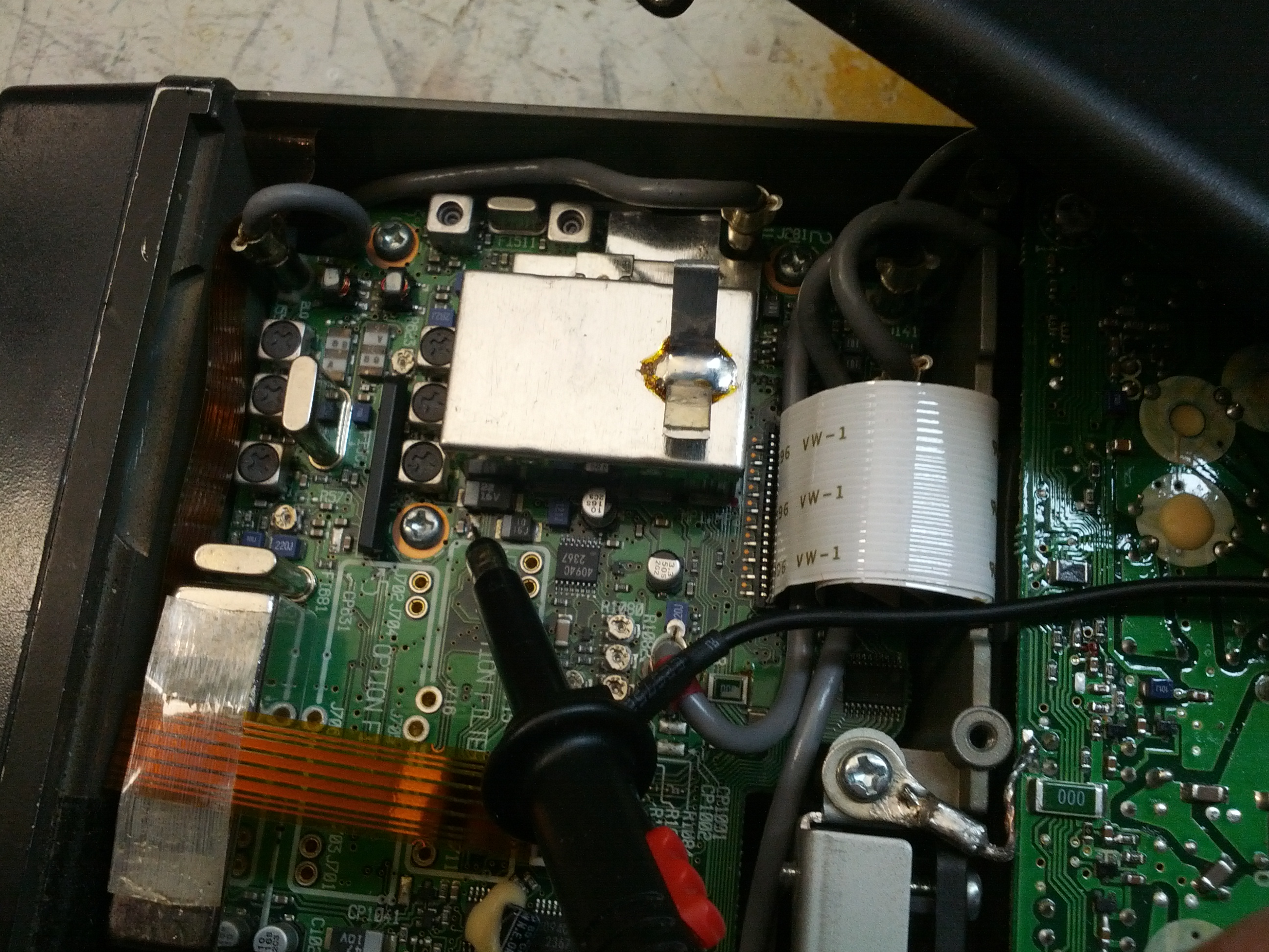
This is the small battery of PLL tests.
The first check is the 60 MHz reference frequency. After finding and fixing a messed up power switch on my antenna analyzer and after checking it with the scope to ensure I wouldn’t blow up my analyzer, I probed it and found exactly 60.000 MHz. Good.
The second test was of the PLL Loop Lock Voltage. Initially, I found that it was around 300 mV. This was too far outside of the required 2.0 V at 0.03 MHz. I thought for a moment that it might be a typo, although those things NEVER happen…
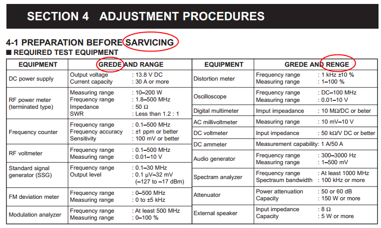
I’ve circled a few of the typos in this – not every one. Apparently I’m SARVICING this radio and I’ve been spelling GREDE and RENGE incorrectly all these years.
…and moved on to test the Main Loop Lock Voltage. It was far less than the spec 4.0 V on the first test (at 129.99999 MHz), so I didn’t continue tests.
After some replies to the post on the Amateur Repairs group, I tried again to recalibrate the PLL circuit and was able to do it. This was, of course, after I removed a shield to test two transistors. I’ve reinstalled it in the truck and so far, so good. But we’ll see. It could have been that the PLL was off causing weird errors that may have changed as voltages to the radio changed (it is mobile, after all), or it could be that something is still bad.
-73-
Update 2104-01-31
The problem came back. I tried switching out the power cable with the one I used in testing last time, and it was to no avail. At this point, I am going to do more testing to determine if this is an FM-only problem and/or if this is a VHF-only problem.
Problems
(1) Scratchy receive on 2M FM. Haven’t tested other bands or modes. Scratchy-ness sometimes goes away in a sudden fashion (like flipping a switch). It’s very much like a bad connection.
(2) Low audio volume
Potential Solutions from Research
From http://groups.yahoo.com/neo/groups/ic706/conversations/topics/17676:
Tighten chassis screws
From http://groups.yahoo.com/neo/groups/ic706/conversations/topics/14813:
“there is a known problem where the power connector is very close to a component (part of the 2m bandpass RX filter) mounted on the board. So close, that it can be knocked off the board when the power cable is plugged in or removed.”
From http://amfone.net/Amforum/index.php?topic=25009.0:
“Make sure the faceplate contacts are clean. Mine goes dead a couple times a year in my truck from this.”
From AB8SH (local friend):
Check the power connection. The Molex connector used by Icom is frequently problematic.
From unnamed (and increasingly difficult to find) posts on the IC-706MKIIG Yahoo Group:
The power connector has been mentioned multiple times on the IC-706MKIIG Yahoo Group. Additionally, the ground clips have been commonly mentioned. Frequently, these are mentioned with the 17m oscillation problem.
Reality
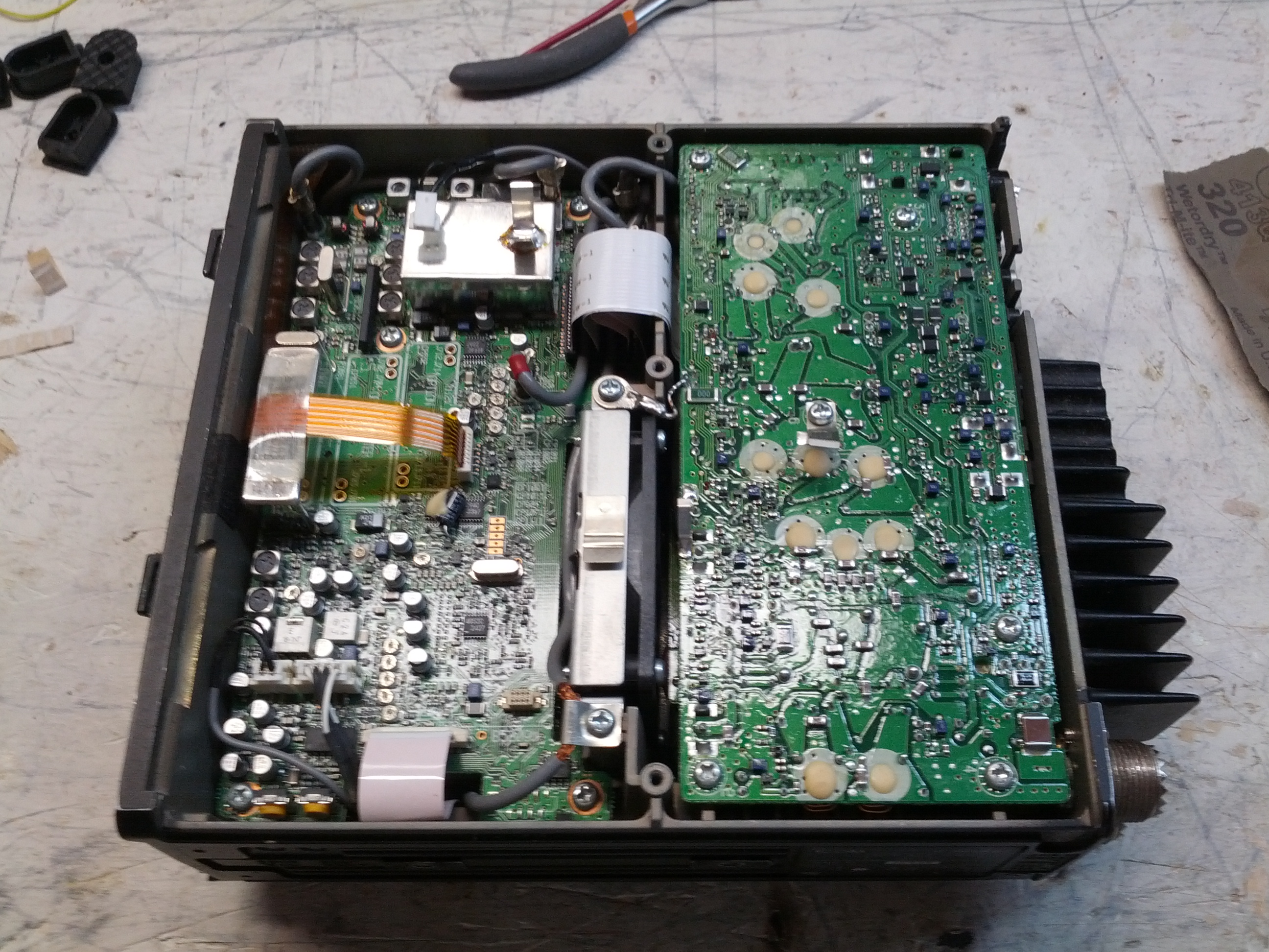
First thing I checked was power and ground connections. The ground clips (that should connect to the case) weren’t putting a lot of pressure on things. I bent all of them up towards the the case for good measure, although I’m not sure that fixed anything. I also ensured that all the internal screws on the PCBs were tight (all of them were).
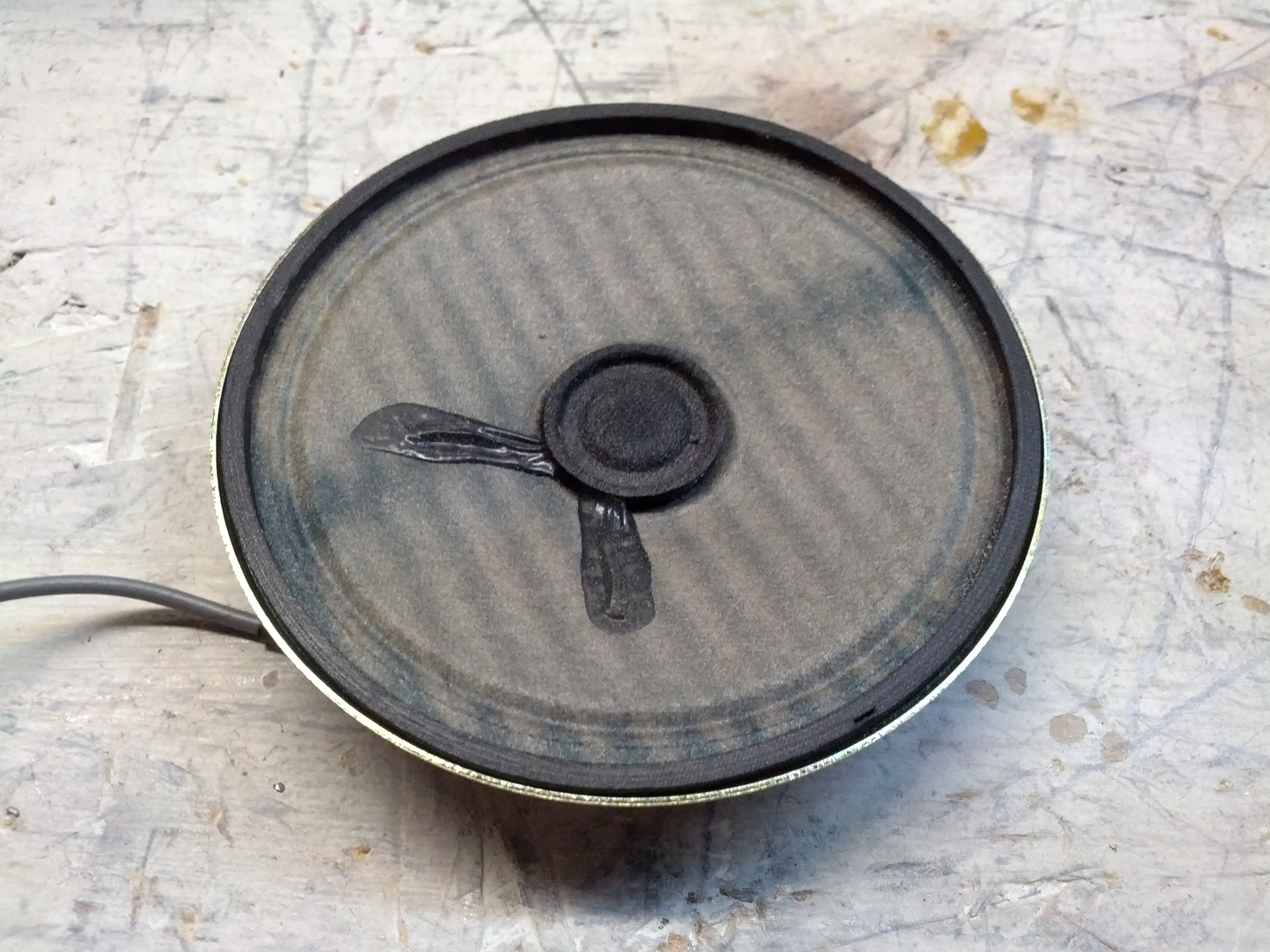
The speaker looks aged (heck, you can see UV discoloration in the cone). Otherwise it looks fine.
After putting the rig back together, I put it on the radio bench connected to a DIFFERENT power cord and it seemed fine. A few days later, I mounted it in the truck. After driving a few miles and getting stopped at a long traffic signal, I decided to tilt the rig up more (yes, I had an appropriate Philips head screwdriver with me) and while being stopped at the light I quickly unbolted the front two mounting screws and tilted it up.
The radio died.
I (still quickly) finished bolting in the radio and while stopped at other traffic signals attempted to jiggle the power connector in the back to no avail. When I got to my destinations (another ham’s house), I found that the plug came out. In subsequent testing, it seems everything is fine.
So What Was It?
I’m banking on a bad power connection. That being said, any mobile setup should probably include proper securing of power connectors and ensuring that road vibration won’t cause things to come loose.
Edit: It is likely the power cord. I noticed static since posting this, so I’m going to replace the power cord and check the pins on the current one.
The finals are replaced and tested! 110 watts out!
So I started looking over things. One thing I’ve been looking into is the zero beat. It seems to me that when you push the button, it should emit the CW tone. I can get it to emit the tone, but only after pressing the zero beat button many times.
I also don’t like the CW tone. It seems odd even when at the correct frequency. I hooked up the audio output to my oscilloscope and saw the audio output… It looks…er…interesting.
I think I was expecting to see more of a sine wave as opposed to a sawtooth (I guess) wave.
There is one minor little problem – it appears the antenna isn’t properly connected to the receive part of the circuit, because it can’t hear anything. It does transmit on the correct frequency (per my antenna analyzer), so the problem is likely minor as opposed to something going bad related to the frequency or mixer.
So after spending last weekend looking over things, I put everything back EXCEPT the finals and the speaker. I rigged a little power cord with alligator clips (I don’t have another plug for this radio) and a circuit breaker on the hot line. I connected the hot to the fuse in the radio and the ground to the radio chassis and powered up the supply. I was greeted with the radio lighting up 21.2027 MHz. I couldn’t hear anything, as I had the speaker removed.

So the next thing I did was resolder the speaker and the the finals. After finding a nylon washer for the internal hot wire in the finals, I did the minimum replacement of screws and powered the unit back up. It immediately popped the circuit breaker.
Guessing that the finals were bad, I removed the finals and powered the rig back up. The display came back up, but no sound out of the speaker. I started adjusting the volume and RF gain trying to hear something. I then noticed that the mode switch was set to “LOCK”, so the transmitter was on. One thing I did notice is that no power was coming out – I had the internal antenna connection connected to my little QRP dummy load that has a rectifier output and I had my multimeter connected to it and there was no DC voltage coming through the dummy load and no read on the frequency counter in my antenna analyzer.
While there is a slight flaw in my troubleshooting, I’m fairly confident that the problem is the finals and I will be taking a closer look at the module tomorrow.
Incidentally, I looked up the price for new finals at RF Parts. $60 for a pair, and $25 for one. Of that’s the problem, it’ll be a fairly inexpensive fix.
Now that I’m done cussin’ at the software (which was doing what it was supposed to, I just didn’t realize that), I have some time to reflect.
First off, 15 and 20 meters were awesome. 10 meters stunk for me – lots of calling from CA, but nobody was hearing my 25 watts from Ohio. 40 meters looked good as well. More on that in a second.
I netted 960 points in 40 QSOs. Two new DX – Cuba and the UK. One #WATwitter – @VA5LF.
I started on 20 and got several. Went to 10 (I think I got one Q there), went to 15 and tore it up. Back to 20, found a few new. Jumped to 40. On my 3rd QSO on 40 my rig quit. Just quit. I thought it had folded back (like it had high SWR). So I turned the rig off and back on. The rig lit up for a split second before dying again. Tried it again, same result. Again. Again. Put my hand on the heat sink on the back. I did NOT yell “ouch!” (or anything of the sort). It was warm, but not hot. Did the same to the power supply, and the same result. I unplugged everything and took the rig over to the bench and removed the covers. Nothing looked burned or bad, but I couldn’t see in the finals. Figuring that’s where the problem would be, I uncovered the finals. Nothing.
So I replaced the bottom cover and moved the rig aside and got the power supply. I tried to pull a pass transistor off the back, but after trying to pry it off with a knife I realized it was soldered on. So I replaced the screws on the pass transistor and plugged it back in to try and put a load on it. After plugging it in at the bench and turning it on, the transistor that I was trying to pry popped from the location I tried to pry it from.
So at least I know I have a bad pass transistor. Maybe two. The rig condition is unknown. I’m going to get a battery and hook the rig to it and see if the rig runs. I honestly don’t want to hook my Astron PS to it, as I don’t want it to blow if there is something wrong with the rig.
-73-
I am working on a Realistic (Radio Shack) HTX-100. I purchased two of these for $45 last May, and was told “one works, one does not”. I joined the HTX-HF_Tech Yahoo group and started looking into things.
The initial problem (but not the ONLY problem) was that there was a lot of static noise from the speaker. This noise was internal to the radio (thanks to a troubleshooting tip I got on Google+ that told me to short the antenna center to shield at the back of the radio).
I started poking around at things, and found that a trimmer resistor was dirty and was causing the static. Combined with the fact that the speaker was desoldered from the board (an oh-so-difficult fix!), I thought maybe I fixed it.
Then I hooked it up to an antenna and checked its ability to receive. Nothing. I could tune stations in on one HTX (and on my Ten-Tec), but not on this one. In fact, I couldn’t tune anything.
One of the things available (not only on the group but also from a few additional websites) is a repair manual, which is really very helpful. I started into the alignment procedure and noticed that in step 3, I was nowhere near the target value of 10.695 Mhz, and was not able to adjust to get anywhere close. So I started looking at the troubleshooting section for the PLL board (where the coil in step 3 was located). A few steps in the process, I checked voltages on one of the ICs and found a handful of them off. I started checking further, and questioned a crystal. I replaced the crystal and found no change. So, I started looking at other things. I checked the voltages on other ICs and found a handful of others that are off. I looked at capacitors, and noticed a few that have tears that seem to indicate that they’ve failed. I replaced one that I happen to have, and it fixed one of the voltages on one of the ICs. Progress! I have a few more to do, but I need to order the parts.

Blown Capacitors on the HTX-100 PLL Board

Main Board of HTX-100

PLL Board of HTX-100
-73-
Last summer, a friend brought me an Astron RS-35 Power Supply to repair. It had been involved in a near-lightning-strike experience that fried the loading coil on an antenna, among other things. The problem was that as soon as the supply was switched on, it would blow the fuse. The only thing that was obvious was that something was causing the SCR crowbar circuit to fire and blow the fuse to save the power supply.
I started out by checking the bridge diodes and filter capacitors. All seemed fine. I checked the pass transistors and those were fine. During a last resort, I removed an electrolytic capacitor and replaced it with another of the same value, but less voltage. My hope was that the voltage on the original capacitor was unnecessary, or that I would have enough time to test a few things before it blew.
Of course, it never happens that way. I had about 15 seconds (not enough time) before letting the magic smoke out of the capacitor. So, since I’m not an electrical engineer, I decided to run a few tests on the blown cap. I noticed that there was no physical damage to the capacitor EXCEPT a small hole in the jacket.
So after staring a little at the schematic (there is an awesome resource on the Repeater Builder website), I decided to remove a capacitor (C6 on the schematic image below). It seemed like a likely possibility, since this was part of the SCR firing circuit (the part I circled in orange highlighter).

Low and behold, it was it! I replaced the part with a new one, and the power supply is done!
-73-