
Tag Archives: rotator
Backstory:
I’m writing most of this as the ARRL June VHF contest is underway. With the 706 still laid up (parts did NOT come on Friday the 13th with a full moon… positive omen? No.), it’s on the bench gathering a little dust.
So I noticed in QST the August 70cm contest. I have 20′ (+/-) of masts, and 20 watts on 70 cm, and I can make an antenna… but I would need a good directional antenna because I have no interest in buying a 400 MHz linear amp for a contest that I may not have any contacts in.
“Good directional antenna” means a yagi or a quad. It also means it needs to be rotatable. I could just turn the entire mast, but I don’t know how that will work – my poles are fiberglass, and will have to be guyed, so that may be easier said than done. I have a junk box full of stepper motors, I have some Arduinos… this could get fun. Even better, it is temporary, so I don’t have to drop big bucks to do this.
So my thinking is that I want an inexpensive home-built rotator. I want the rotator to know where the antenna is pointing, and there are two components to this – a rotation sensor to tell me where the antenna is pointing and a sensor to act like a compass to tell me where north is.
All that being said, this is post 1 of 2.
Angular Sensors
For the hobbyist, there are basically four encoder options: optical, magnetic, capacitive, and mechanical. These can be incremental – where it tells you that there is change and how much the change is (or a pulse on change) or absolute (where it gives you a specific position).
Optical
Optical encoders are commonly found in printers and scanners, and the same concept was used by Ben Heckendorn on his Doggie Treat Dispenser. These have an optical sensor that looks for dark/light marks on a disk on a rotating shaft. I don’t know about prices for these, since I have a few of them from a coworker’s printer that stopped working.
Magnetic
Magnetic encoders operate by using a magnet and a hall effect sensor to sense the change in the magnetic field due to the magnet’s rotation. I’m guessing (operative word!) that these are bad to use in strong magnetic fields (like near a motor, hard drive, or one of those big electromagnets used in junkyards to lift cars).
It appears the only magnetic encoders available (for hobbyists) are analog – they give a voltage output based on the rotational position. This has the benefit of being absolute or semi-absolute. Prices range from $10 to $45 from the big US suppliers. Their use with an Arduino would be similar to the use of a light sensor (although the voltage divider may be built into the sensor, so you may not need to have one separate).
Capacitive
Capacitive encoders work similarly to optical encoders, but instead of using a beam of light, it uses a set of disks and a capacitance sensor. Benefits (according to CUI) are that dust can mess up optical encoders and that LEDs can burn out.
Capacitive rotary encoders run around $25 and provide up to 2,048 positions of output (that’s one every .18 degrees!). Looking at the linked item, it seems to be the most ready-to-use sensor, depending on the application.
Mechanical
Mechanical rotary encoders are common in selector switches. They have mechanical rings inside (I couldn’t find a good explanation of how this works). They are inexpensive and common, but I’m not sure of their use within an antenna rotator. Truthfully, the amount of torque needed to turn a selector switch is so much that I’m not sure this is really an option.
Next Step
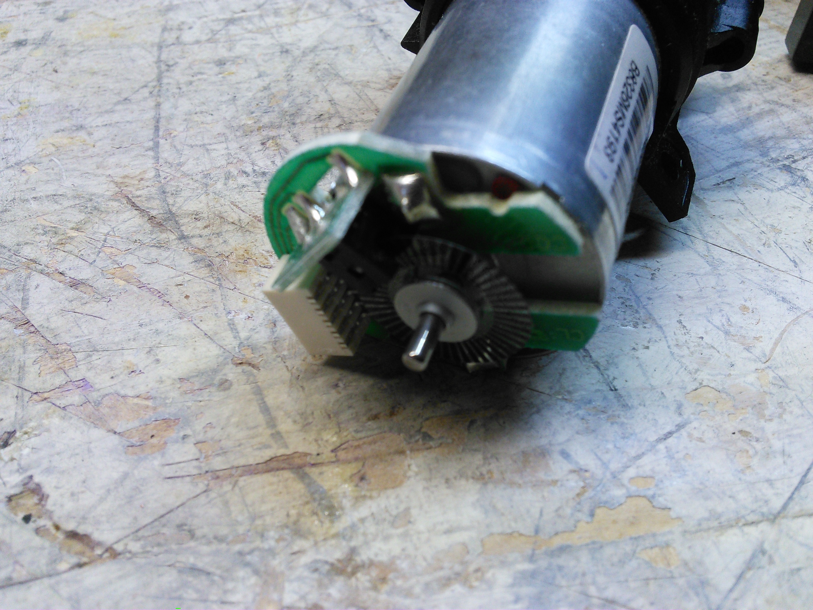
As the only picture on this post indicates, I have a motor with a sensor. I am going to build that into some sort of rotator that can be mounted on top of a fiberglass pole that I can use to turn the antenna. I don’t know if I can have it done by August, but I’m going to try… presuming I get the 706 fixed first!