
Tag Archives: tc74
With all the issues surrounding FTDI chips and drivers, I decided I’d look at a competing chip – the Microchip MCP2221. Unlike the “standard” FTDI FT232 (which is most similar to the MCP2200), the MCP2221 includes both a UART and an I2C interface.
Hookup and Configuration
Hookup
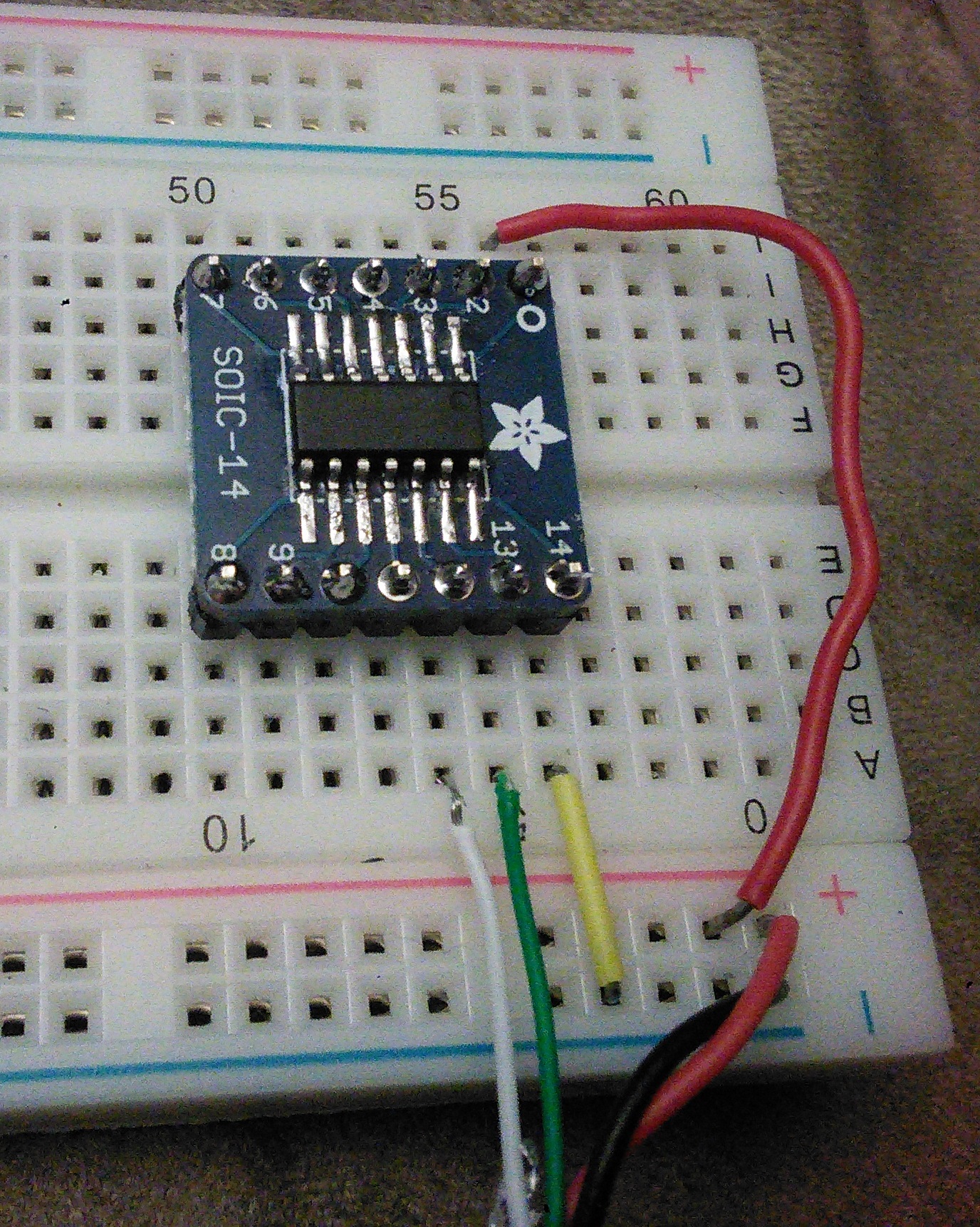
Hooking up this is pretty easy. I sacrificed a USB cable and pulled the red to Vcc on pin 1, black to ground on pin 14, white to Data- on pin 12, and green to Data+ on pin 13.
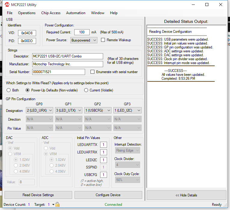
After that, I checked things using the Microchip MCP2221 Utility from Microchip. One of the more interesting things in the utility was being able to configure four pins:
GP0 (pin 2), default is UART RX LED, but can also be SSPND (suspend?) or GPIO
GP1 (pin 3), default is UART TX LED, but can also be CLK_OUT (clock out?), ADC1, IOC, or GPIO
GP2 (pin7), default is USBCFG, but can also be ADC2, DAC1, or GPIO
GP3 (pin 8), default is I2C LED, but can also be ADC3, DAC2, or GPIO
I2C Connection
The real reason I got this was to be able to interface to both I2C devices and UART (serial) devices, so I hooked a TC74 temperature sensor to it.
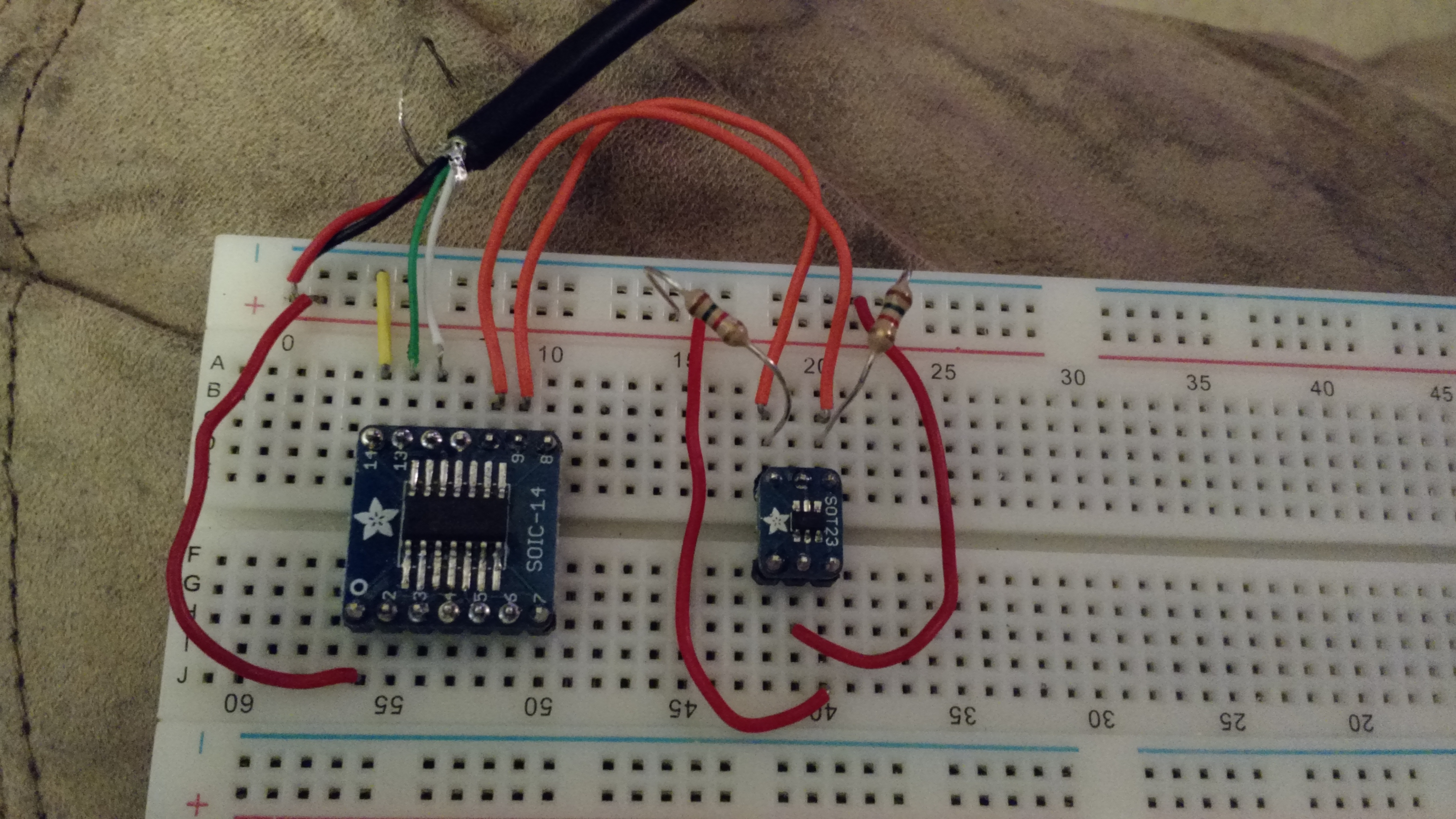
TC74 hooked up to the MCP2221
The hookup is straightforward, the TC74 uses four of it’s five pins, Vcc, ground, SCL, and SDA. Vcc and ground are pretty self explanatory, SCL and SDA go to pins 10 and 9 on the MCP2221 (respectively). The SCL and SDA lines need pull-ups, I used 1.5k resistors.
To check things, Microchip provides an I2C/SMBus Terminal program.
Under “Advanced settings” you can scan the bus by giving it a range to scan…
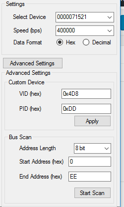
Scan the entire bus
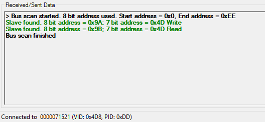
Scan results. Found the TC74 right where I expected it.
Once I verified that the sensor was where I thought it was, I used the terminal tool to read it…
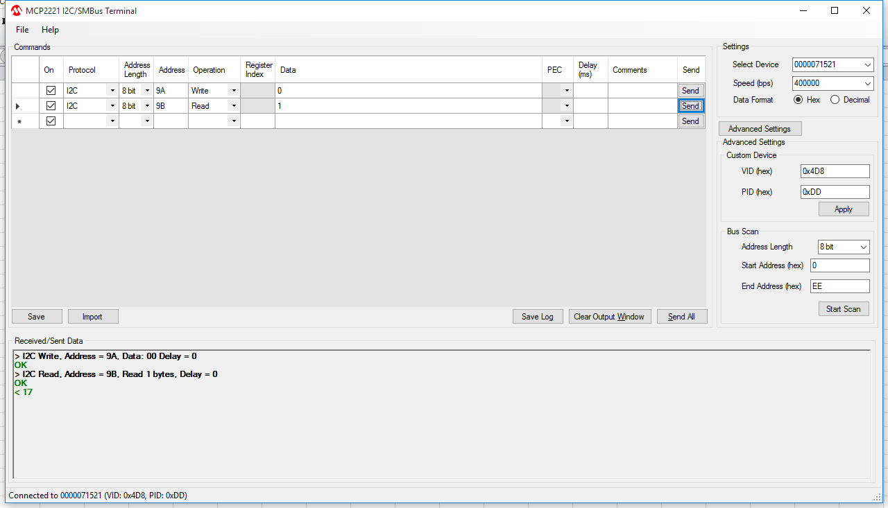
0x17… 23C… 74F…
So the next steps are to figure out what I want to do with all this… I’m partly thinking a multi-function breakout board – UART, ADC and DAC
-73-
The Bus Pirate Demo Board has five I2C devices: two 24AA02 EEPROMs (2 KBit), one TC74 temperature sensor, one MCP4725 D/A Converter, and one DS1307 Real-Time Clock. This post is about the EEPROMS and the TC74 – next week’s post will be about the D/A converter and the RTC.
Pull-up Resistors & Connections
One thing that is not documented well enough for non-engineers is the pull-up resistors. They are pretty important for I2C devices and results can be weird. What needs to happen is to have BOTH the 5V and pull-up lines to the Vin pin on the demo board. I used a breadboard for now, although I have a different Bus Pirate cable on the way to make this a little easier.
In both the cases in this post, the CLK pin on the Bus Pirate gets connected to the SCL pin on the demo board and the MOSI pin on the Bus Pirate gets connected to the SDA pin on the demo board.
EEPROMs
Both of the EEPROMs are interfaced the same way.
Search for the EEPROM Addresses:
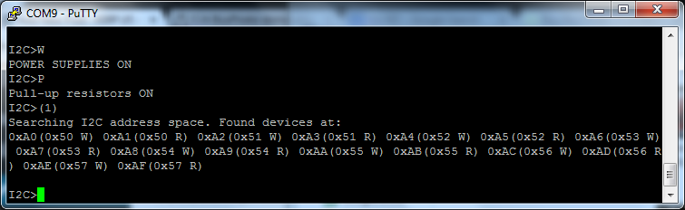
(1) is the address search address
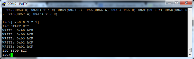
[0xa0 0 3 2 1] – 0xa0 is the address to write to, 0 is the location in that address (the top), and 3, 2, and 1 are the values being written.
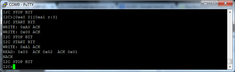
[0xa0 0][0xa1 r:3] – 0xa0 is the address, 0 is the location in the address. 0xa1 is the read command, and r:3 indicates to read three bits.
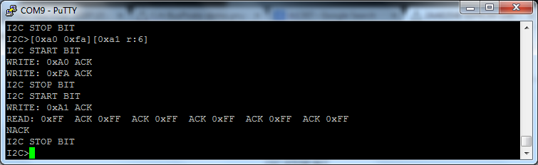
[0xa0 0xfa][0xa1 r:6] – this is to read a MAC address from the chip. Unfortunately, I can only seem to get all F’s from these chips… I’m not sure if I’m doing something incorrect or if the chip’s spec has changed since the instructions on Dangerous Prototypes were written.
As a final test, I cut the power to the board (w) and turned it back on (W) and read the chip to see if the values were still there. They were.

TC74 Temperature Sensor
The TC74 Temperature Sensor is an interesting device to use.
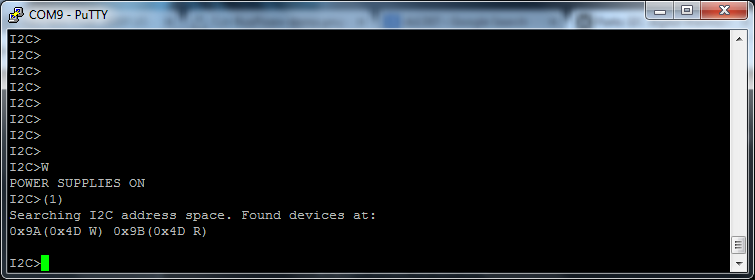
(1) – standard address search macro
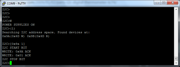
[0x9a 1] – 0x9a is the address, 1 is a value to write. We don’t really care what it writes, we just need to do this to read the chip.
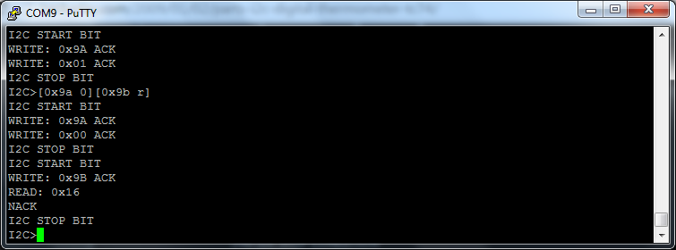
[0x9a 0][0x9b r] = 0x9a is the write address, 0 is a partial command to select the temperature register, and 0x9b r reads the register.
The value returned is 0x16, which is 22°C, or 71.6°F.
…next week – more I2C goodness!
-73-