
Category Archives: Equipment
This is the second post on the Bus Pirate Demo Board I2C, showing the MCP4725 digital to analog converter and the PCF8563 real-time clock.
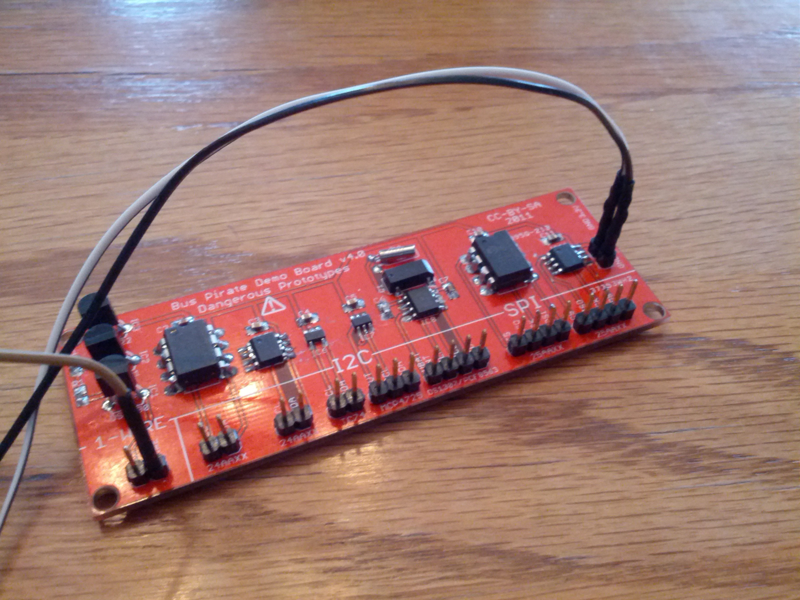
Connections
Like the last post, the ground and Vin need to be connected, and VPU (the pull-up resistors) need to be connected to the Vin as well. CLK on the Bus Pirate needs to be connected to SCL, and MOSI on the Bus Pirate needs to be connected to the SDA pin. There are other connections that will be necessary and will be different for each.
Digital to Analog Converter
The additional connection that needs to be made for this is the ADC connection on the Bus Pirate should be connected to the OUT pin on the demo board. This will allow you to see the output. As shown in this video by Mike Parks, it is pretty easy to address and use.
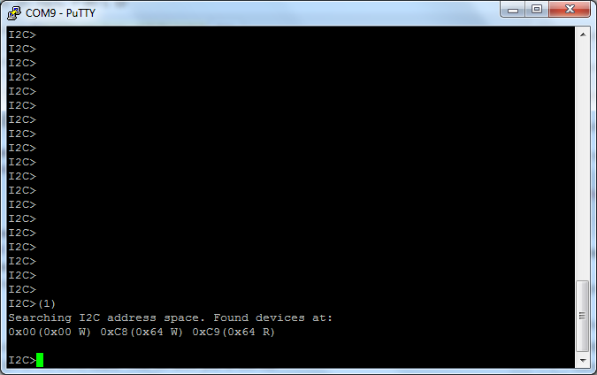
(1) – macro to search for address
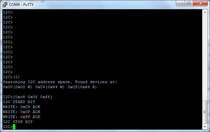
[0xc8 0x0f 0xff] – turn the analog output to full
v – show voltages
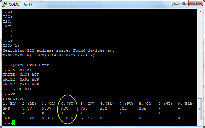
Note the ADC voltage, which is at 5.03V (the max it will show).
To change things, try using [0xc8 0x01 0x00]. It will set the voltage to 0.30V. using …0x00 0x00 will turn the ADC to 0V. It is linear from 000 to FFF hex, so 800 (0x08 0x00) is half, and so on.
Real-Time Clock
The RTL uses the same SDA, SCL, and power connections as above, and those are the only necessary connections. However, the ADC and AUX connector CAN be used if wanted.
Setting and retrieving the time can be done using the following (ref):
(1) – address search macro
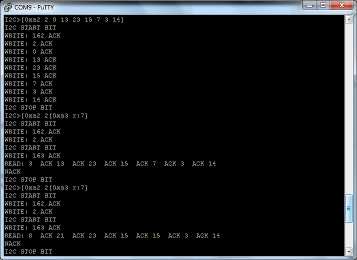
[0xa2 2 0 13 23 15 7 3 14] – 0xa2 is the address, 0 is the location to write, and I’m writing
[0xa2 2 [0xa3 r:7] – 0xa2 is the address, and 2 is the address to READ from in the next command, 0xa3 is the read location, and it reads 7 bits.
It seems to me that connecting the AUX on the Bus Pirate to the CLK pin on the clock should be measurable (by using f in the BP interface), but I’m not seeing a reading, so it may not be the correct way to use that. However, when I took the AUX wire and held it to pin 1 on the RTL IC and read the frequency, it came up to 60 Hz, and was not controlled by sending commands to the 0x0d address.
-73-
The Bus Pirate Demo Board has five I2C devices: two 24AA02 EEPROMs (2 KBit), one TC74 temperature sensor, one MCP4725 D/A Converter, and one DS1307 Real-Time Clock. This post is about the EEPROMS and the TC74 – next week’s post will be about the D/A converter and the RTC.
Pull-up Resistors & Connections
One thing that is not documented well enough for non-engineers is the pull-up resistors. They are pretty important for I2C devices and results can be weird. What needs to happen is to have BOTH the 5V and pull-up lines to the Vin pin on the demo board. I used a breadboard for now, although I have a different Bus Pirate cable on the way to make this a little easier.
In both the cases in this post, the CLK pin on the Bus Pirate gets connected to the SCL pin on the demo board and the MOSI pin on the Bus Pirate gets connected to the SDA pin on the demo board.
EEPROMs
Both of the EEPROMs are interfaced the same way.
Search for the EEPROM Addresses:
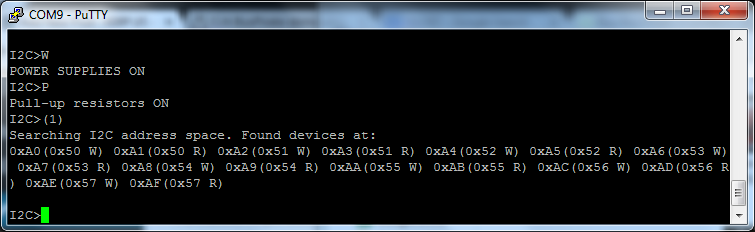
(1) is the address search address
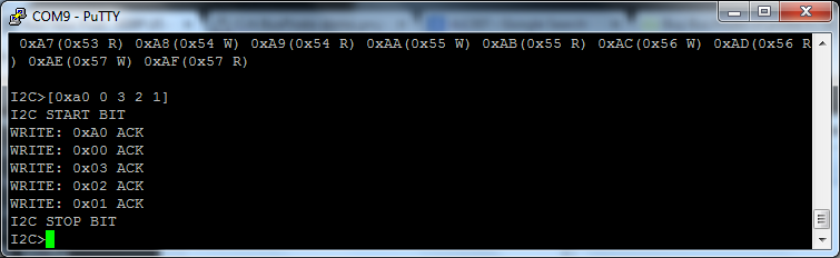
[0xa0 0 3 2 1] – 0xa0 is the address to write to, 0 is the location in that address (the top), and 3, 2, and 1 are the values being written.
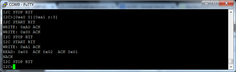
[0xa0 0][0xa1 r:3] – 0xa0 is the address, 0 is the location in the address. 0xa1 is the read command, and r:3 indicates to read three bits.
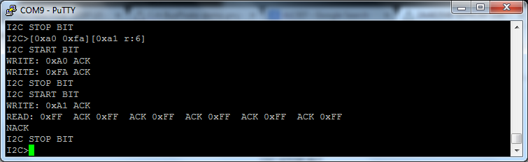
[0xa0 0xfa][0xa1 r:6] – this is to read a MAC address from the chip. Unfortunately, I can only seem to get all F’s from these chips… I’m not sure if I’m doing something incorrect or if the chip’s spec has changed since the instructions on Dangerous Prototypes were written.
As a final test, I cut the power to the board (w) and turned it back on (W) and read the chip to see if the values were still there. They were.

TC74 Temperature Sensor
The TC74 Temperature Sensor is an interesting device to use.
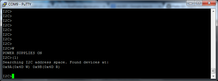
(1) – standard address search macro
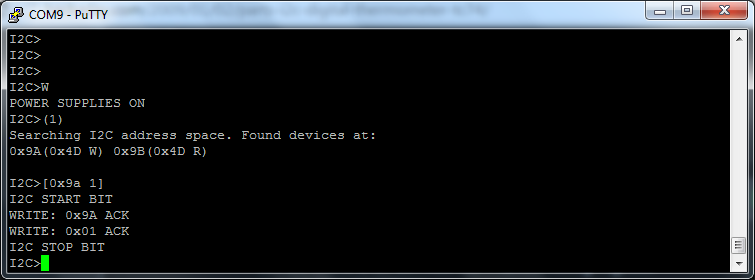
[0x9a 1] – 0x9a is the address, 1 is a value to write. We don’t really care what it writes, we just need to do this to read the chip.
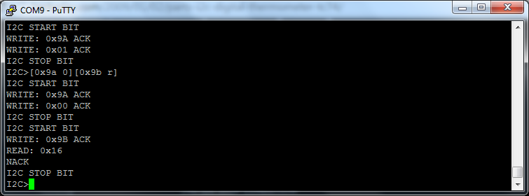
[0x9a 0][0x9b r] = 0x9a is the write address, 0 is a partial command to select the temperature register, and 0x9b r reads the register.
The value returned is 0x16, which is 22°C, or 71.6°F.
…next week – more I2C goodness!
-73-
In learning how to use the Bus Pirate, I started with the one-wire area of the demo board.
First off, important notes:
- I’m using the v 3.8 Bus Pirate. The pinout is different than some of the others.
- I’m using a Sparkfun Bus Pirate cable.
My cable is as follows:
Black: Ground
White: 5V
Grey: 3V3
Purple:VPU
Blue: ADC
Green: AUX
Yellow: CS
Orange: MISO
Red: CLK
Brown: MOSI
The first part of this is based on using the DS2431 1,024 bit (1 kilobit?) EEPROM. The second part is using the DS1822 temperature sensor.
1K EEPROM
I used the instructions on Dangerous Prototypes as a guide.
This is how I had the demo board hooked up.
I hooked the ground (black) to the ground, the 5V (white) to Vin (the 3.3-5V pin), and MOSI (brown) to One Wire. Then, open the bus pirate and get into one-wire mode (m {enter} 2) and turn on the power (W). Then, issue the search macro ( (240) ).
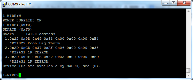
Use (240) or (0xf0) to search the one-wire bus. The bus pirate will return a list of all items on the bus. In my case, I have two EEPROMs (thanks to not being able to get a part) and a temperature sensor.
Writing to the EEPROM to a Temporary Location
I write a string of numbers to one of the EEPROMs here.
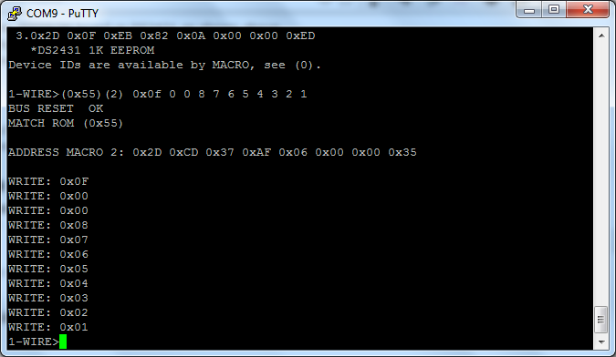
To write some values to the EEPROM, I used the following:
(0x55) (2) 0x0f 0 0 8 7 6 5 4 3 2 1
(0x55) is the macro to ‘match 64 bit address’
(2) is the macro to the address of the EEPROM I’m writing to
0x0f is the command to write to the devices scratch pad
0 0 is the location to write to
8 7 6 5 4 3 2 1 is the data that I’m writing
Reading (Verifying) What I Wrote
I read that string of numbers here.
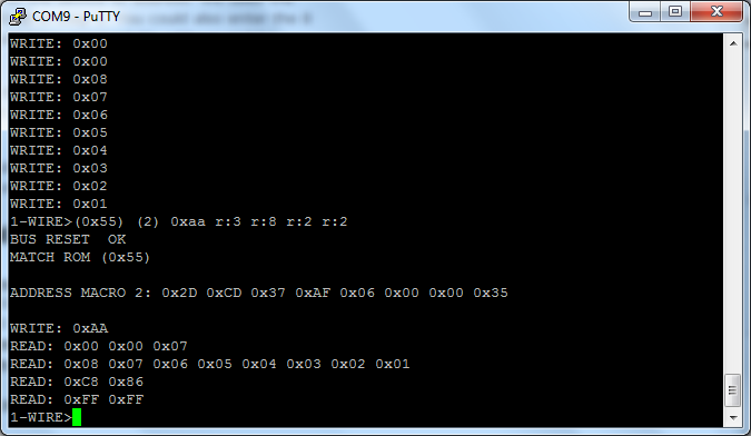
To read the string of numbers, I used the following
(0x55) (2) 0xaa r:3 r:8 r:2 r:2
The first two are similar to above – (0x55) to match the address and (2) for the macro to the address I wrote to.
0xaa is the read scratch pad command
r:3 reads the authorization code (needed to permanently write the data)
r:8 reads the data I wrote in the last step
r:2 reads the CRC
r:2 this is all ‘1’s
The final r2 returns 0xFF, which is 2 bytes of 1s, in decimal this is ‘11111111’ ‘11111111’.
Permanently Writing the Data
I permanently write the data here.
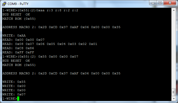
To permanently (well, permanent until I rewrite it) write the data to the EEPROM, I used the following:
(0x55) (2) 0x55 0x00 0x00 0x07
(0x55) (2) is the same as above
0x55 is the command to write the scratch pad to memory
0x00 0x00 0x07 is the authorization code from above
Verifying the Write
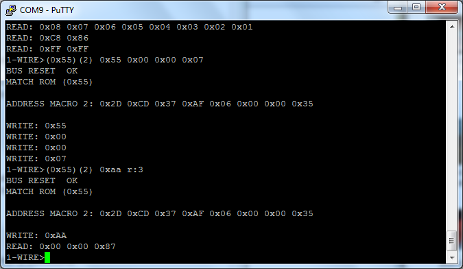
I verify the write here.
To verify the write, I used the following:
(0x55) (2) 0xaa r:3
(0x55) (2) is the same as above
0xaa is the read command (same as above)
r:3 means read three bytes. The data that is returned is 0x00 0x00 0x87, which is different from before
Reading Back the Data
I read back the values here. These are permanently written to the EEPROM.
To read the data, I used:
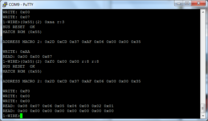
(0x55) (2) 0xf0 0x00 0x00 r:8 r:8
(0x55) (2) is the same as above
0xf0 is the read command, but this is read from the memory, not the scratch pad
0x00 0x00 is the address
r:8 r:8 reads 8 bytes, twice
The first string returned is 0x08 0x07 0x06 0x05 0x04 0x03 0x02 0x01, which is the data we wrote. The next string is 0x00 0x00 0x00 0x00 0x00 0x00 0x00 0x00, which is data that was never written, so it is all zeros.
That’s it! I read and wrote to a small EEPROM. If it isn’t obvious from the picture above, this is about the same size as a small BJT transistor.
Reading from a DS1822 Temperature Sensor
The DS1822 is a one-wire temperature sensor that is also the size of a BJT transistor. Reading from it is pretty easy and was described on Hack-A-Day by Ian back in 2008.
This is in the same setup as above, so looking in the screenshots above, the proper address for this device is (1).
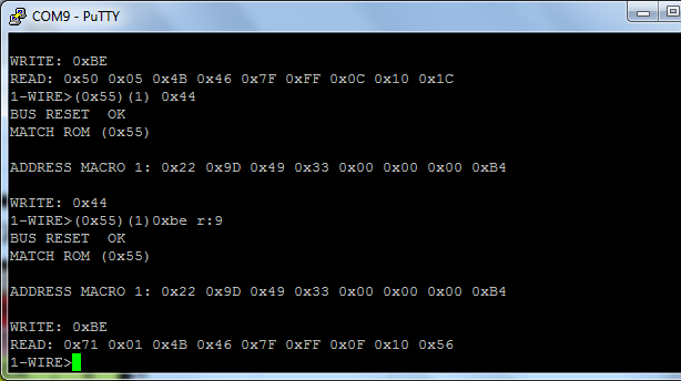
Reading from a temperature sensor.
To read from the device, two commands must be entered:
(0x55)(1) 0x44
(0x55)(1) 0xbe r:9
The first command is a “Convert temperature” command, which basically tells the sensor to read the temperature.
The second command reads 9 bytes from the sensor. The important part are the first two bytes. In the example above, the first two bytes are 0x71 0x01. This translates into being read as 0x171 (see note). That 0x171 needs to be converted into decimal, in this case 369. That number then needs to be multiplied by the resolution, which if never changed is 0.0625. That comes out to a temperature of 23.06C, or 73.5F.
-…-
This is the first of a multi-part series. Next installment in this series (hopefully next week) will be the I2C bus, although depending on the length (there are several chips there), it may be broken into two parts.
-73-
A few weeks ago, I got a Free PCB from Dangerous Prototypes for a Bus Pirate. This is a pretty cool hardware swiss army knife that I’m still learning how to use.
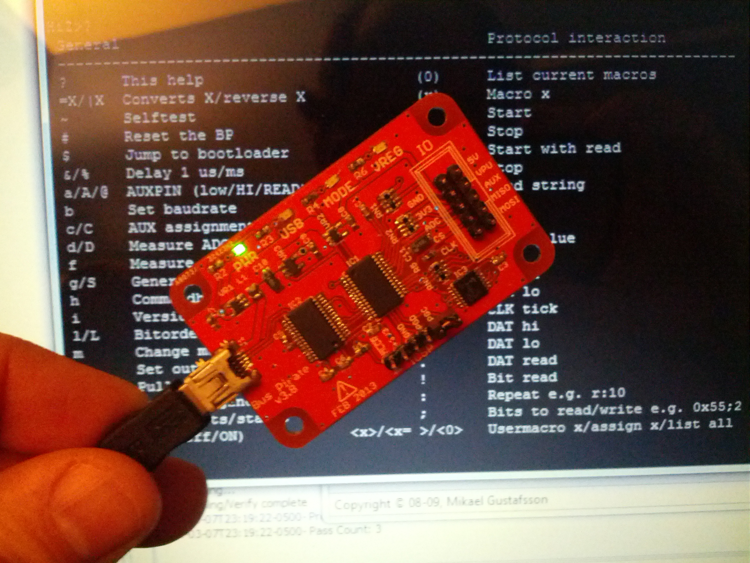
This is the bus pirate in front of the terminal background.
I had a few issues with the build (none a fault of Dangerous Prototypes or the PCB manufacturer). First off, I didn’t get the LEDs on correctly the first time, and I’m pretty sure I didn’t get the USB one right the second time, either. Also, I didn’t get good solder joints on the PIC24. I was seeing problems that were identical to these reported on the DP Forum, and feared that the FTDI chip was fake. After removing the FTDI chip and pulling one from another FTDI board I had, I tried sjaak’s advice of pushing on the chips and found that if I pushed on one part of the PIC24, the VREG light came on, so I reflowed the solder on both chips and voila!
I also learned that PIC chips aren’t as easy as Arduinos to burn, and after initially finishing the PCB, I had to order a PICKit3 to burn the chip. It wasn’t a big deal to order the PICKit, but it was a nearly week delay as I inadvertently (and unknowingly) selected a shipping option that used UPS for the long haul from Ft. Worth to Cincinnati and then used the postal service to deliver it the last 2 miles from the post office to my house (to use another ham’s quote, “you get the incredible slowness of the ground services + the normal 2 day delivery of USPS. you save cents. yay!?” … yeah, that’s about right – 100 cents to add two days to the delivery time).
I did slightly deviate from what I think was intended with this – this was built for a USB Micro connector, but I put a USB Mini connector on it. It hangs off a little, but I’m fine with that (I have minor personal reasons too, but it really boils down to preference).
I also deviated on the connector. I didn’t look back in my order history to get the correct connector, and ended up with an incorrect connector. So I put header pins on it and called it done.
A final thing I learned was the value in over-ordering. Since I’m not a pro in this, my parts orders tend to be small, and normally there is a price break at 10. Having extras on hand means that as soon as I get a PCB, I can start building right away.
Thanks to Dangerous Prototypes for the PCB! I’m already learning a lot about using it and I’m (of course) using my last free PCB build to learn more about using it.
-73-
For anyone on the Amateur Repairs (*cough* yahoo *cough*) group or who follows me on G+, YouTube, or Twitter, you’ve likely seen posts related to my IC-706 mkIIG. I’ve pulled the radio out of service because of problems primarily on VHF-FM (at least it seems that’s where the problems are at). In fact, since early December, I’ve been sporadic with transmitting with it, and I haven’t transmitted with it at all since mid-January.
The problem I’m having is extreme static even with very strong signals. I’ve checked the likely (hopeful?) culprits of power cords and antenna connections. Since things seem to be fine on those – I’ve tried two power cords and three power sources and two different antenna setups – I’ve moved on to checking internals.
My first check was for anything obvious. Like this, this, or even this. Nothing. I don’t know if I should say “fortunately” or “unfortunately”.
My second check was to poke around inside. I first looked at some of the audio waveforms at the NB test point and the WFM test point. Pretty interesting to see on a scope, and they didn’t react to volume (that’s a good thing, as this is likely before the audio amp!).
The Noise Blanker Test Point
(PS in the video above: yes, I’m checking that with an oscilloscope probe. It works, even if it isn’t necessarily ‘right’… or maybe it is, I don’t know).
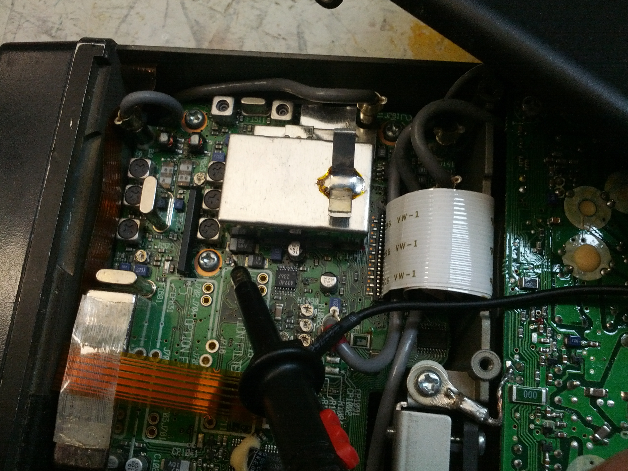
My second test was to do something more … practical. I know from some of the reading I’ve done in the ARRL Handbook, the owners and service manual for the rig, a video from Kenneth Finnegan (from The Life of Kenneth blog that I follow), and some comments from Mike M. on Google+ that maybe I should check the PLL board. And besides, checking stuff is easy, right?
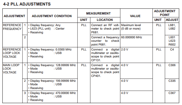
This is the small battery of PLL tests.
The first check is the 60 MHz reference frequency. After finding and fixing a messed up power switch on my antenna analyzer and after checking it with the scope to ensure I wouldn’t blow up my analyzer, I probed it and found exactly 60.000 MHz. Good.
The second test was of the PLL Loop Lock Voltage. Initially, I found that it was around 300 mV. This was too far outside of the required 2.0 V at 0.03 MHz. I thought for a moment that it might be a typo, although those things NEVER happen…
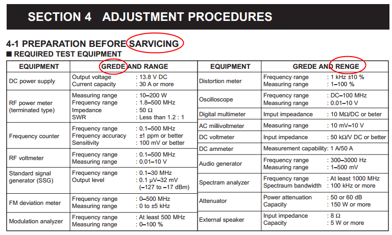
I’ve circled a few of the typos in this – not every one. Apparently I’m SARVICING this radio and I’ve been spelling GREDE and RENGE incorrectly all these years.
…and moved on to test the Main Loop Lock Voltage. It was far less than the spec 4.0 V on the first test (at 129.99999 MHz), so I didn’t continue tests.
After some replies to the post on the Amateur Repairs group, I tried again to recalibrate the PLL circuit and was able to do it. This was, of course, after I removed a shield to test two transistors. I’ve reinstalled it in the truck and so far, so good. But we’ll see. It could have been that the PLL was off causing weird errors that may have changed as voltages to the radio changed (it is mobile, after all), or it could be that something is still bad.
-73-
Before getting back into ham radio, I did something that I later found to be not optimal – I purchased a very nice 50″ plasma TV. It sounds like everyone else’s YouTube video of Plasma TV RFI, but if you want to see mine, the video is below.
I’ve looked into different solutions that remove noise based on a noise antenna, like the MFJ-1025 Noise Canceler. I believe these items work by inverting the phase of the noise and mixing it back with the signal to remove the noise. It is absolutely critical that these items have a great noise antenna in order to remove it.
The real issue I have is shown in the video above – the noise is picked up in the antenna. I believe that it is primarily picked up by the feed line because it is near (enough) to the front of the TV. See the diagram below:
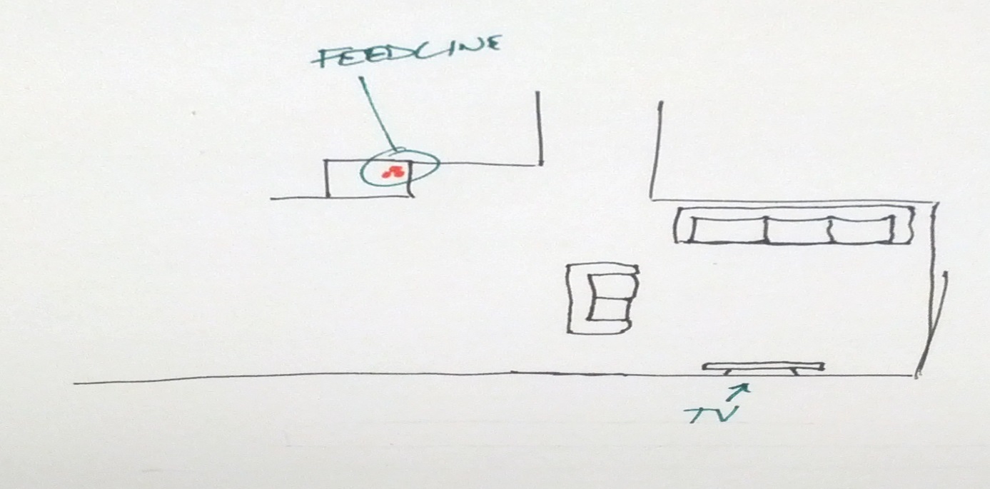
So in order to use a noise canceling device, I’d need an antenna along my feed line.
I decided to try something else first – shielding my coax. I bought a pair of lengths of EMT conduit to run the coax in. This has a second advantage of being able to run coax really quickly. The only disadvantage is that I can’t use ladder line in it. Given the situation, no big loss.
So right now, this is where I’m at. My HF feed line is crummy RG-58 that has an aluminum shield (insert angry face), so I haven’t tested it yet because I don’t have any crimp PL-259 connectors (nor do I have aluminum solder). Additionally, if this doesn’t work like this, I will ground the conduit to see if that fixes it. If neither does, I’m sure that conduit would be an adequate noise antenna for a noise canceling device.
In other news…
I’ve been virtually off the air because of a problem with my IC-706. I posted something to Google+ and received a response that I need to look into, but I’m still looking for more clues as to why I’m getting major static on FM receive.
The filter sweeper is “stalled” because of work on other things. I will be getting back into it because I may want (or need) it for that crystal IF filter problem indicated in the G+ post mentioned above.
-73-
I’m not going to call it a spectrum analyzer anymore – the way I’ve designed this, it isn’t going to do the same things as a spectrum analyzer.
The main difference is that a spectrum analyzer can operate without a signal generator, this won’t because the signal generator is what is going to tell the Arduino what the frequency is.
I built another shield to stack onto the shield in last week’s post.

There is currently no connection from the DDS to this yet, but that’s one of the only few things left to do on the hardware side.
I also built a filter that will ultimately be the first filter to test. This is for my Softrock 20/30/40 and should pass 7 MHz while filtering 14 MHz.

This will fit in a Radio Shack small plastic enclosure – the plate was leftover from a small dummy load that I glued into the enclosure.
-73-
Update 2104-01-31
The problem came back. I tried switching out the power cable with the one I used in testing last time, and it was to no avail. At this point, I am going to do more testing to determine if this is an FM-only problem and/or if this is a VHF-only problem.
Problems
(1) Scratchy receive on 2M FM. Haven’t tested other bands or modes. Scratchy-ness sometimes goes away in a sudden fashion (like flipping a switch). It’s very much like a bad connection.
(2) Low audio volume
Potential Solutions from Research
From http://groups.yahoo.com/neo/groups/ic706/conversations/topics/17676:
Tighten chassis screws
From http://groups.yahoo.com/neo/groups/ic706/conversations/topics/14813:
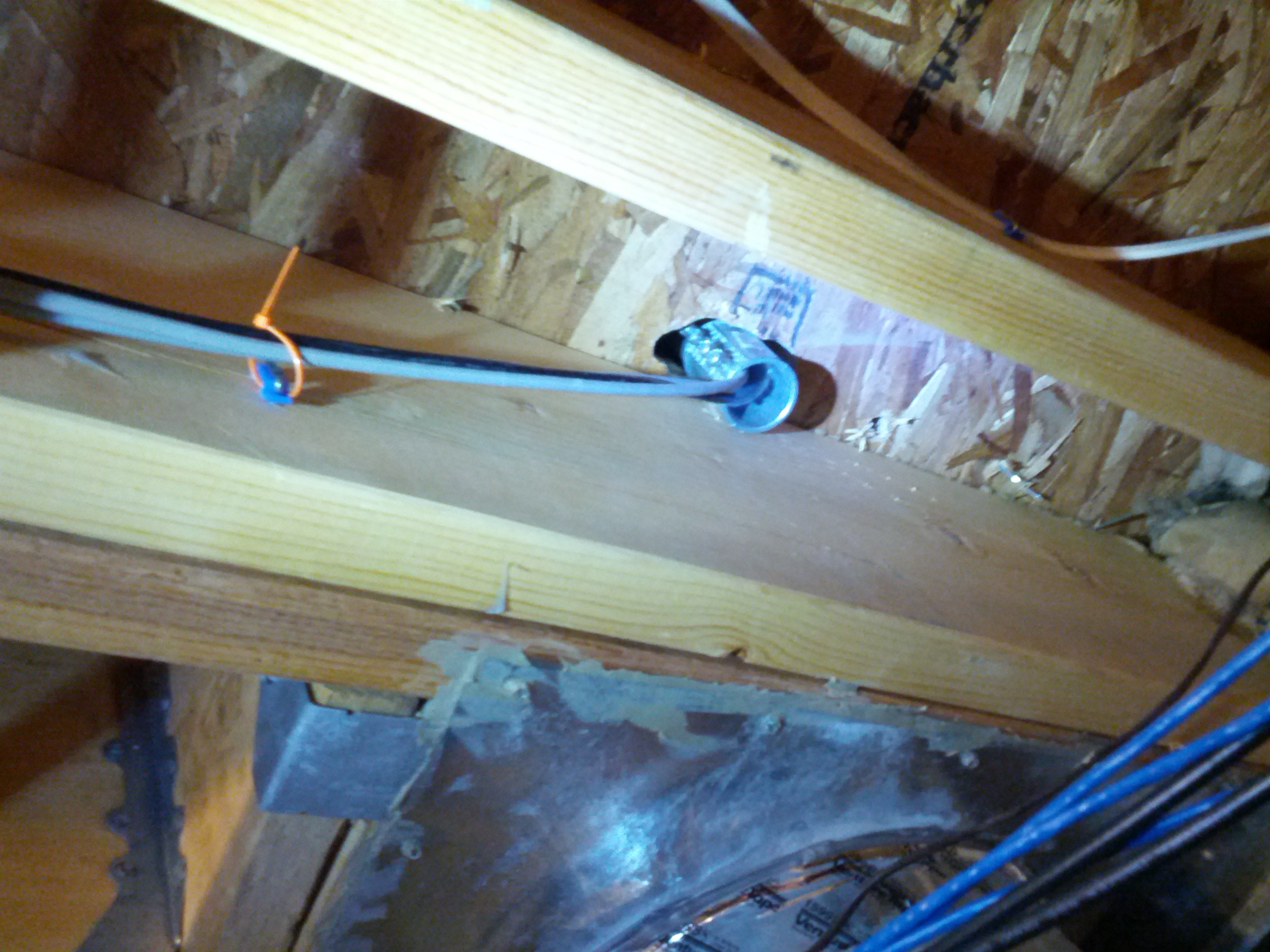
“there is a known problem where the power connector is very close to a component (part of the 2m bandpass RX filter) mounted on the board. So close, that it can be knocked off the board when the power cable is plugged in or removed.”
From http://amfone.net/Amforum/index.php?topic=25009.0:
“Make sure the faceplate contacts are clean. Mine goes dead a couple times a year in my truck from this.”
From AB8SH (local friend):
Check the power connection. The Molex connector used by Icom is frequently problematic.
From unnamed (and increasingly difficult to find) posts on the IC-706MKIIG Yahoo Group:
The power connector has been mentioned multiple times on the IC-706MKIIG Yahoo Group. Additionally, the ground clips have been commonly mentioned. Frequently, these are mentioned with the 17m oscillation problem.
Reality
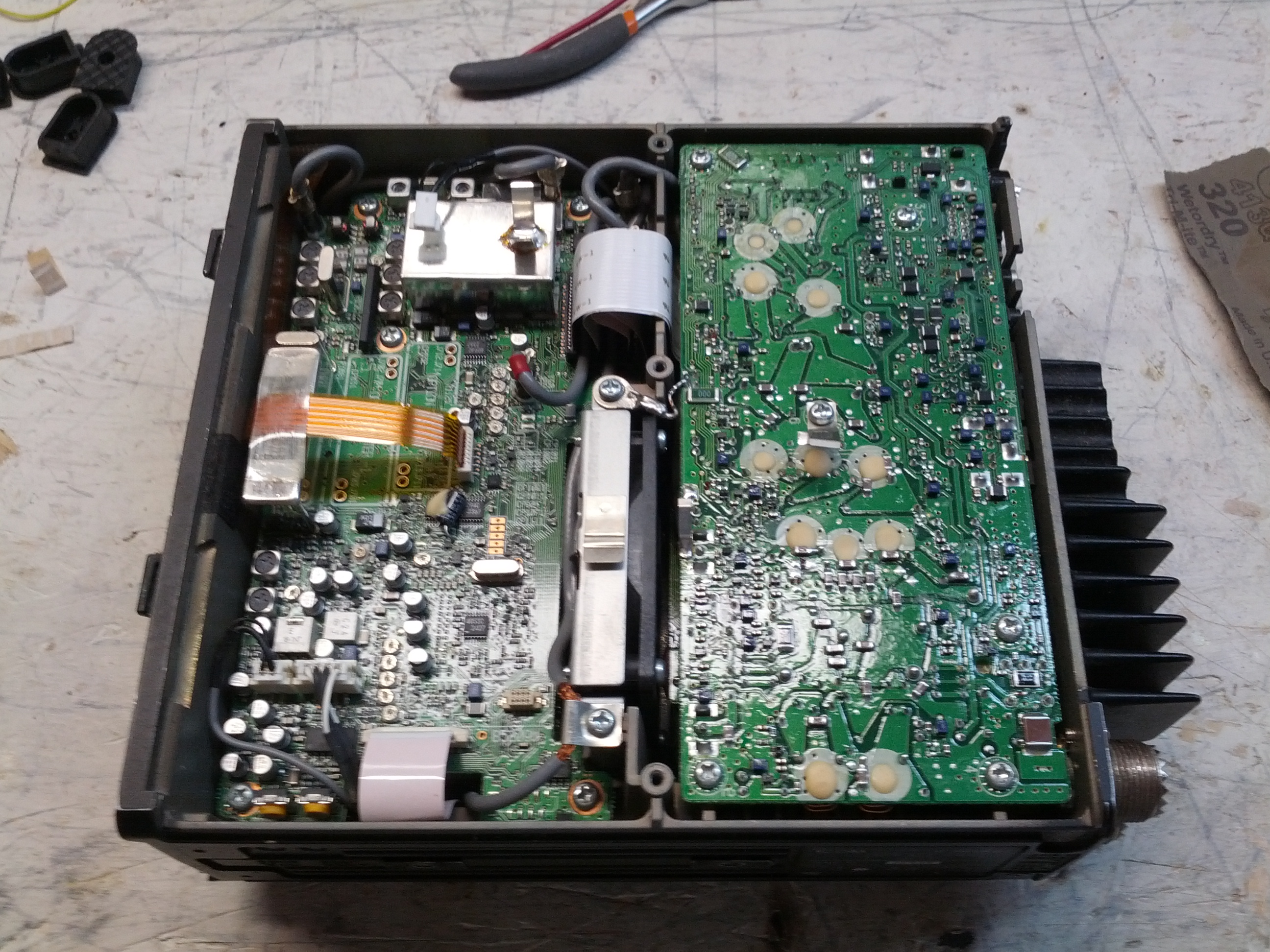
First thing I checked was power and ground connections. The ground clips (that should connect to the case) weren’t putting a lot of pressure on things. I bent all of them up towards the the case for good measure, although I’m not sure that fixed anything. I also ensured that all the internal screws on the PCBs were tight (all of them were).
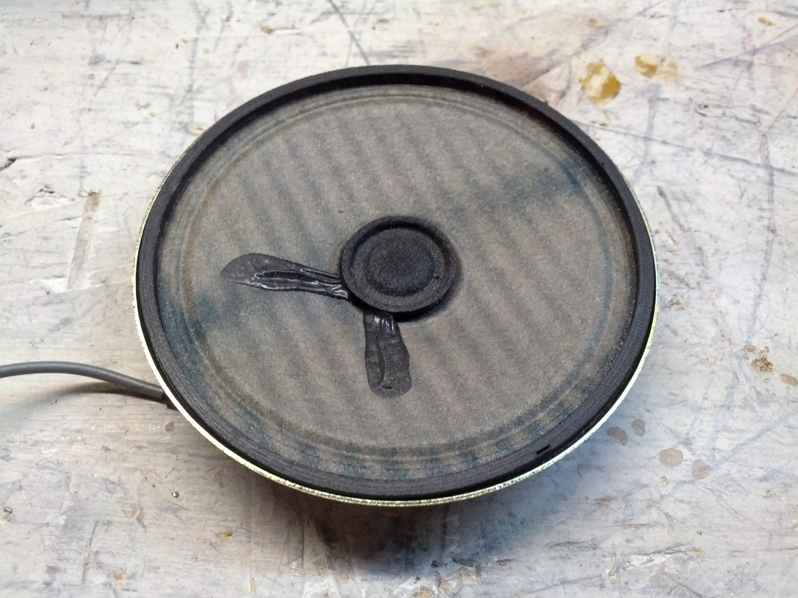
The speaker looks aged (heck, you can see UV discoloration in the cone). Otherwise it looks fine.
After putting the rig back together, I put it on the radio bench connected to a DIFFERENT power cord and it seemed fine. A few days later, I mounted it in the truck. After driving a few miles and getting stopped at a long traffic signal, I decided to tilt the rig up more (yes, I had an appropriate Philips head screwdriver with me) and while being stopped at the light I quickly unbolted the front two mounting screws and tilted it up.
The radio died.
I (still quickly) finished bolting in the radio and while stopped at other traffic signals attempted to jiggle the power connector in the back to no avail. When I got to my destinations (another ham’s house), I found that the plug came out. In subsequent testing, it seems everything is fine.
So What Was It?
I’m banking on a bad power connection. That being said, any mobile setup should probably include proper securing of power connectors and ensuring that road vibration won’t cause things to come loose.
Edit: It is likely the power cord. I noticed static since posting this, so I’m going to replace the power cord and check the pins on the current one.
After building my first PCB a while back and starting to attempt to use it, I decided that the smart thing to do would be to finish build #2, which is a Bus Pirate Demo Board. This demo board has a handful of chips that can be used to test a Bus Pirate (or in my case, a Bus Pirate Shield): 5 EEPROMs, a temperature sensor, a digital-analog converter, and a real-time clock.
My biggest hold-ups were ordering parts… I certainly have a bit to learn about SMD sizes, as I ordered some that were a bit small:
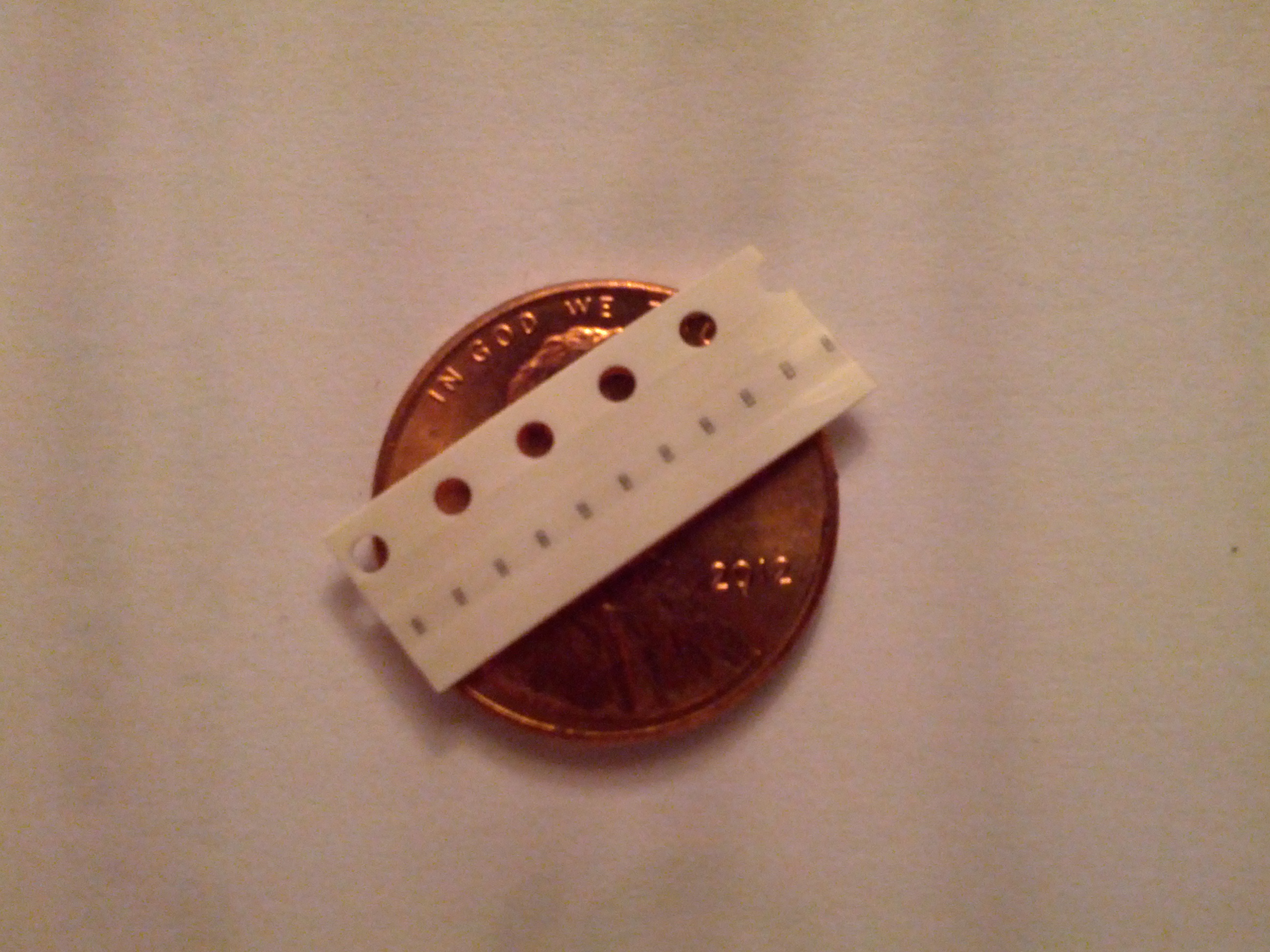
Too small!!!
Finally, after a few extra parts orders, I finished it. I’m getting better at soldering SMD devices, although I should probably invest in a soldering station with adjustable temperature control and a better assortment of tips. My Radio Shack iron runs very hot.
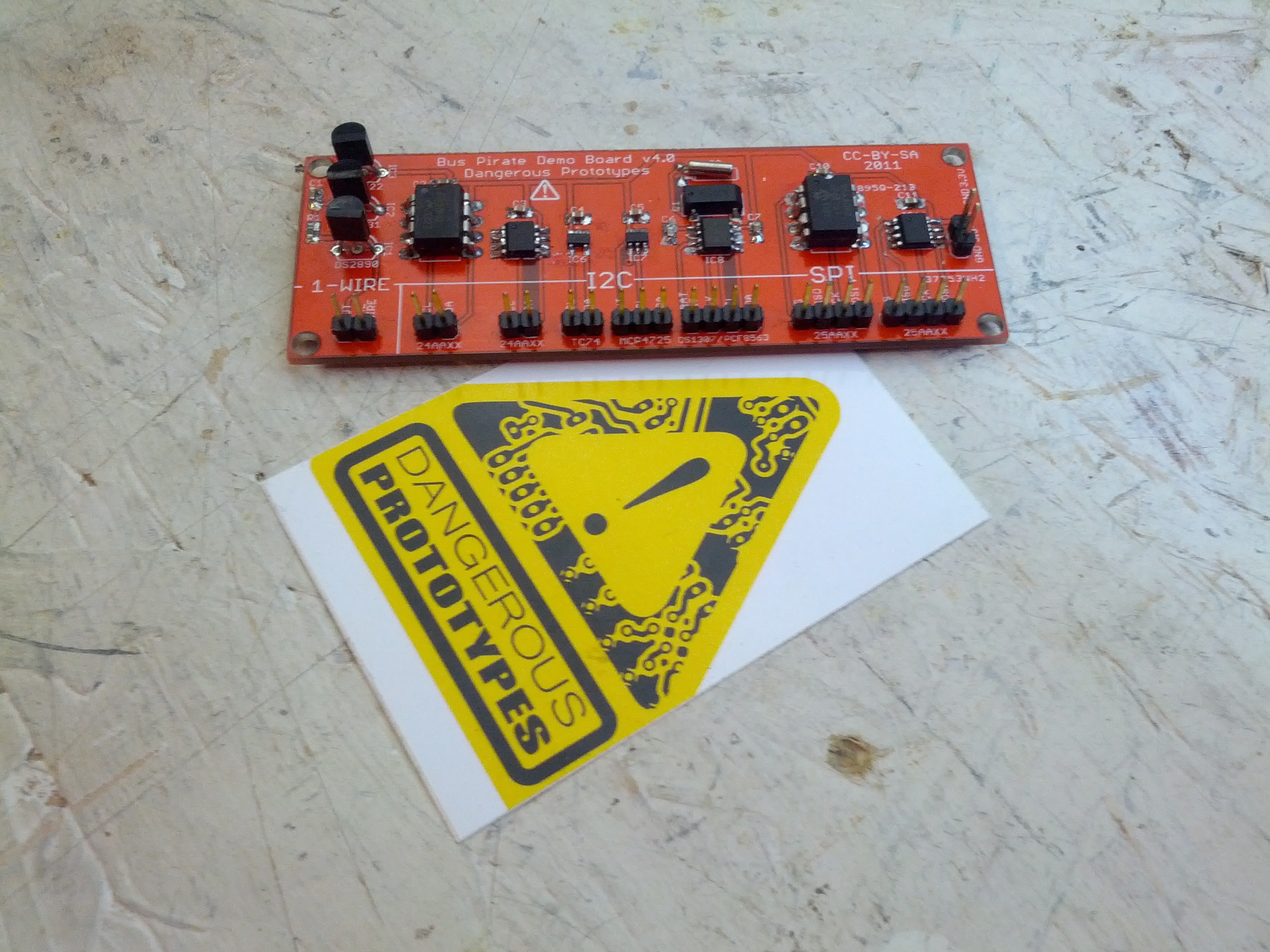
The completed board.
This will make an appearance in a forthcoming blog post, particularly after I get more into using the Bus Pirate Arduino Shield.
-73-
Since I fixed my Ten Tec Omni, I’ve used it a little and I’ve had one major complaint: it doesn’t talk to the computer. In fact, in the CQWW contest, I mistakenly logged my first contact on both the incorrect band and the incorrect mode (I was operating SSB on 10m, and it was logged as CW on 160m… never mind that I have never operated 160m CW!).
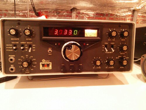
This is the radio.
When I first got it, I started looking at the different inputs and outputs on the back. One is very curious: the VFO in-out, which is shorted together.
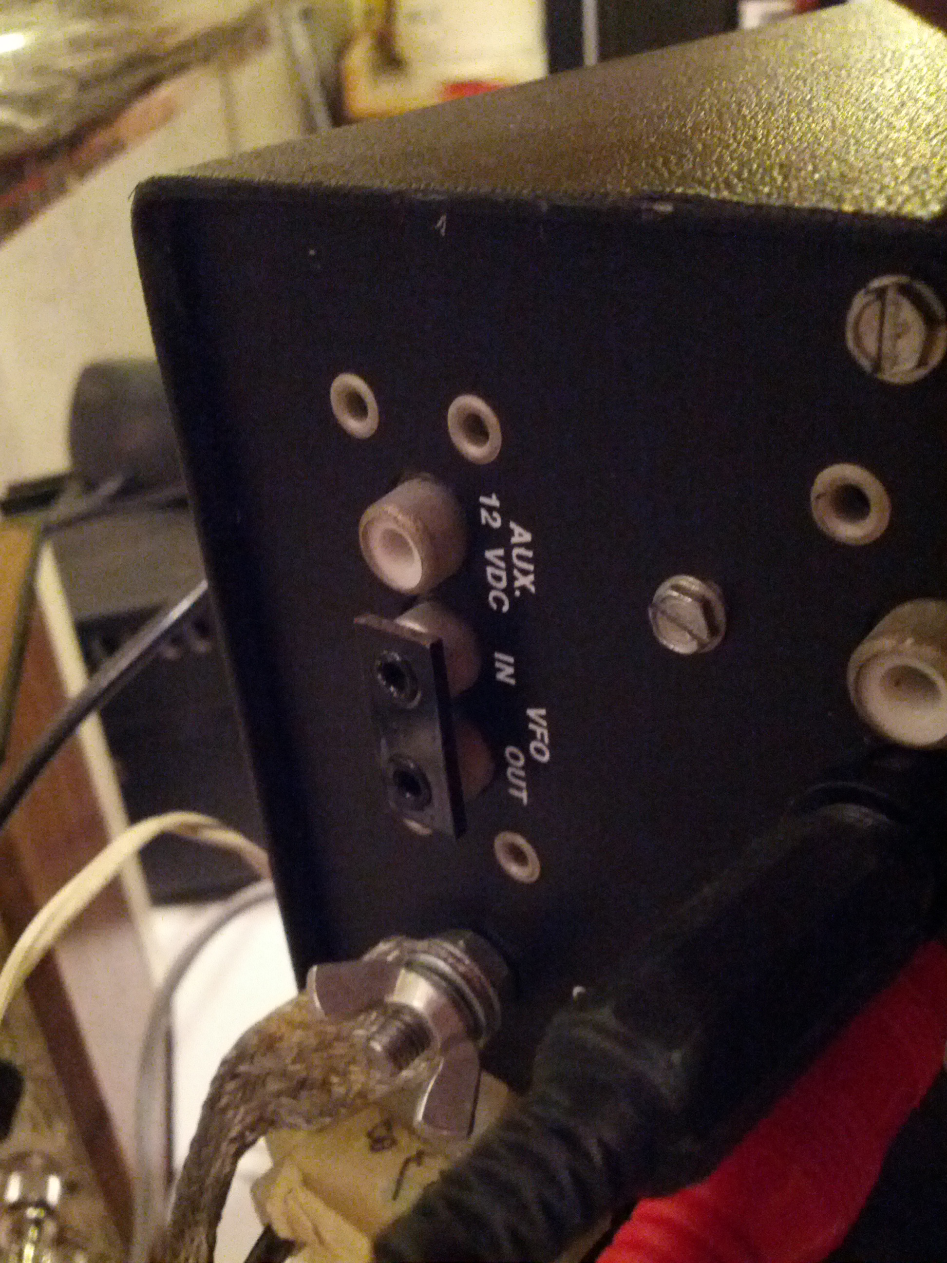
The VFO In and Out RCA jacks.
So I decided to look into what these jacks do. Enter the oscilloscope to check the voltage coming out of there (so I don’t blow my antenna analyzer).
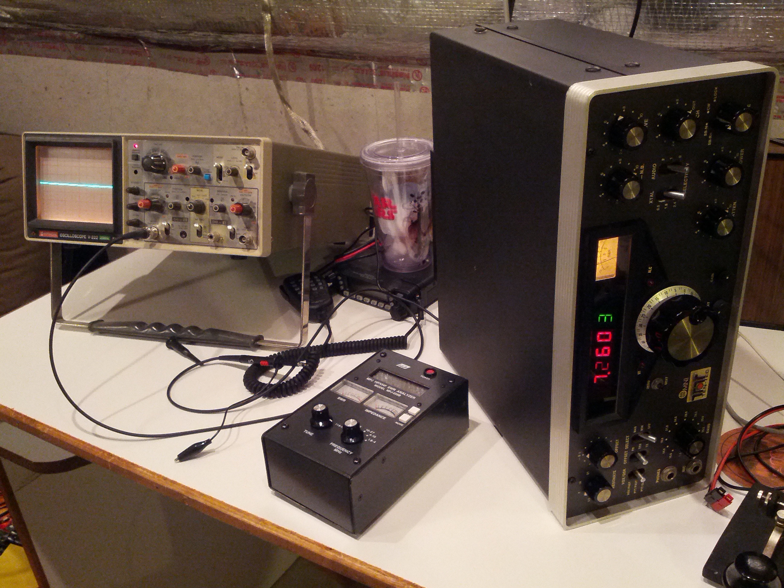
Yes, the Omni is on it’s side.
After checking to insure that there isn’t more than 2 volts peak-peak coming from this (there’s actually about 0.5 volts peak-peak. Once I was sure that it was safe for the antenna analyzer, I took the oscilloscope probe and plugged it into the analyzer to see what frequency that jack used.
I was surprised a little to see that the VFO output for setting the radio at 10 MHz was 5.01 MHz. Then, I started tuning around and seeing a little pattern, which can be seen in the image below:
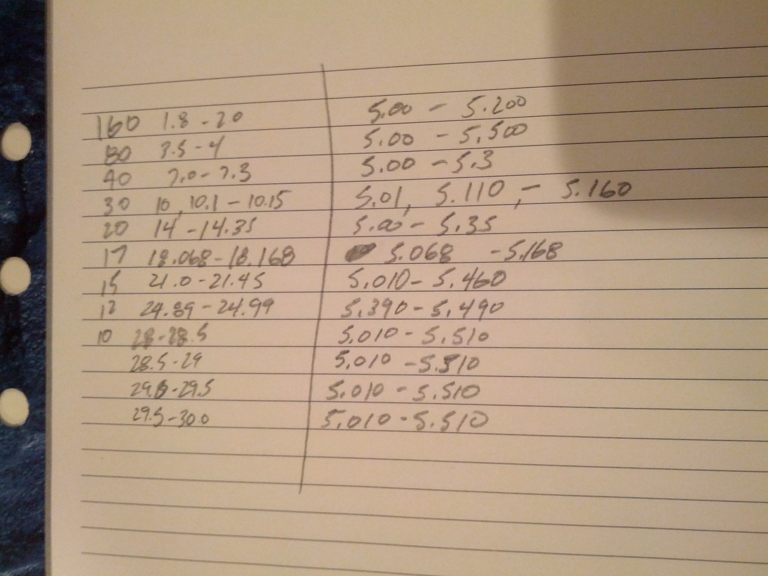
My paper of VFO frequencies for all the bands.
So each of these tells me basically the offset (within 0.01 MHz)
In order to get the actual frequency to a computer, I need to do two things: build a frequency counter that I can plug into something that sends a serial string to a computer, and get the band that the radio is switched to, which would probably come from this jack:
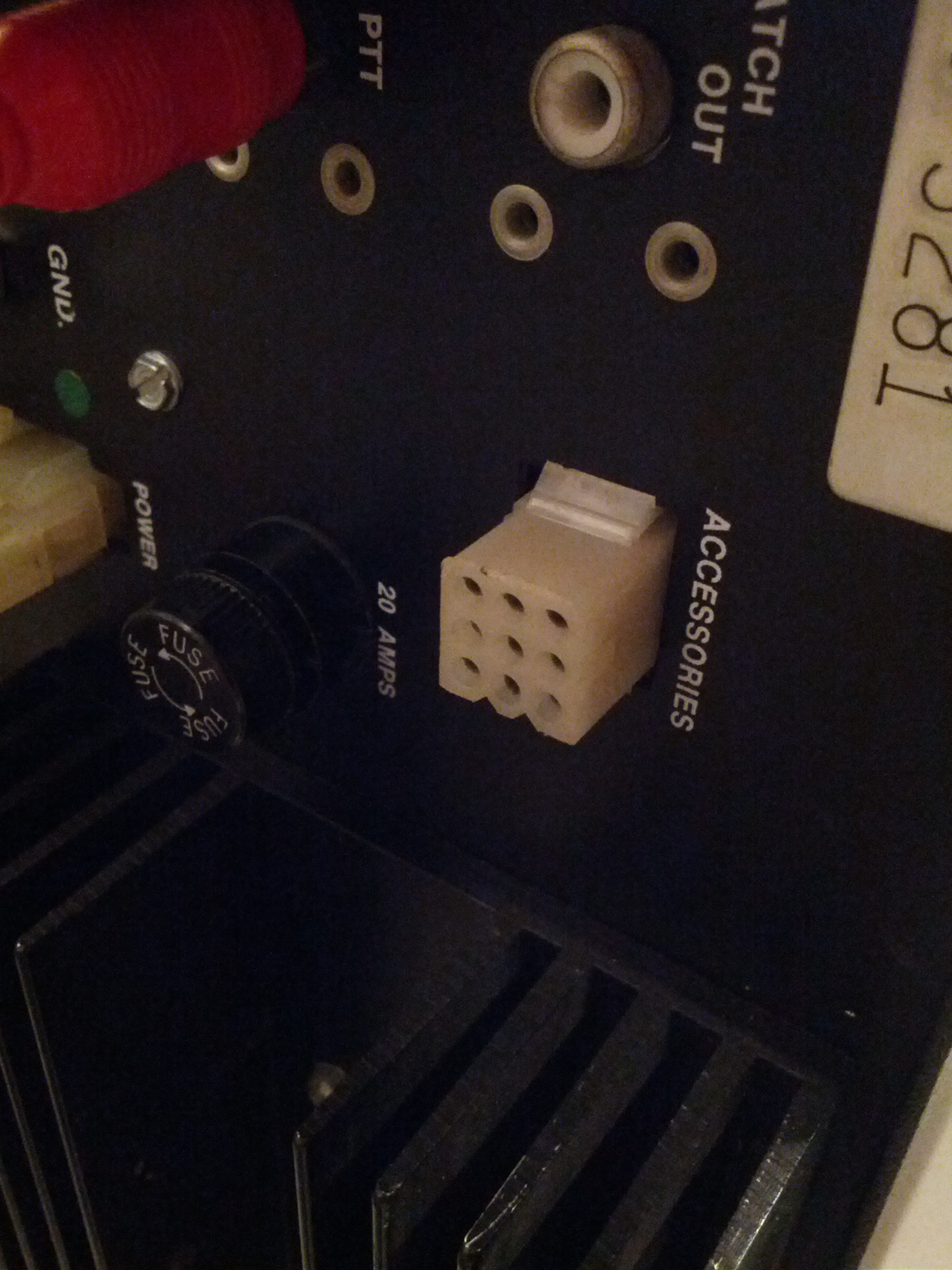
The accessory jack.
Sometime in the future (whenever I get back into working on this), I’ll see if I have the connector for that accessory jack and set up something to read it.
-73-