
Category Archives: Equipment
Last Saturday was the Georgetown Hamfest held by the Grant Amateur Radio Club.
I noticed that during the CQWW contest, I could only get a response from others if I yelled into the mic. I’m sure my wife didn’t care too much for that, and it isn’t good for me, either. So naturally, I went to the hamfest looking for a good mic. I stumbled on a Heil Pro. This is a very small mic, but since it will eventually be attached to an arm, that’s no big deal.

So now I have a mic with a 4-pin XLR connector and need to take it into a 1/4″ stereo jack. I have to deal with impedances (possibly the problem with my current mic, so I may not have truly fixed anything by buying a new mic). Fortunately, I have some known devices to get an idea from. Expect that next week’s blog post will talk about this more in detail.
In the meantime, the mic smells like cigarrette smoke, so I’ve got it sitting in a container of baking soda and will do more later in the week.
First CW QSO… Almost
The big part of getting into the shack Sunday was to do my first CW QSO with another SKCC member that is hunting the prefix award. I couldn’t hear him at all, and he couldn’t hear me. After checking multiple times, I had my daughter hold down the key and I listened on my truck’s radio. I didn’t hear a tone (though I did hear a carrier) and I didn’t see my on the Reverse Beacon Network, so I feared the worst. I checked some of the voltages in the Omni, and finding nothing amiss (and after talking to a few on Twitter about it), I put things back together and looked at things via the Softrock SDR. I was greeted by the sound of a tone, so I guess things are working okay and there was probably another perfectly valid reason why my truck’s radio wasn’t making the tone.
Incidentally, one of the big things I WAS concerned about was that the sound of my rig on the air would be poor, mostly due to the fact that the sidetone generator on my rig is generating a sawtooth (see the video below) instead of a sine wave. Looking at things in SDRSharp put that fear to rest. Hopefully next weekend.
For anyone that’s been following me on Twitter, you’ve undoubtedly seen my tweets about getting some DX on 10m while mobile. For whatever reason, 10m seems to be the sweet spot with my 706 and the hamstick.
The Setup
The current setup is here (old pic)

This is the radio in the lower center console of my truck.
The Issues
One issue with this is that it is difficult to control the radio. Part of it is that I need to use it more. Part of it is that it is just over an arm’s length away. Solution: I have the head separation kit, I need to mount the radio somewhere easier to see and control.
The only other issue is logging. I’ve tried using Google Keep and Evernote, but they haven’t worked very well. Keep tries to transcribe the speech, which it usually does poorly with callsigns and frequencies. It will normally get the ubiquitous “five nine”, though. I’ve decided I need an “easy button”.
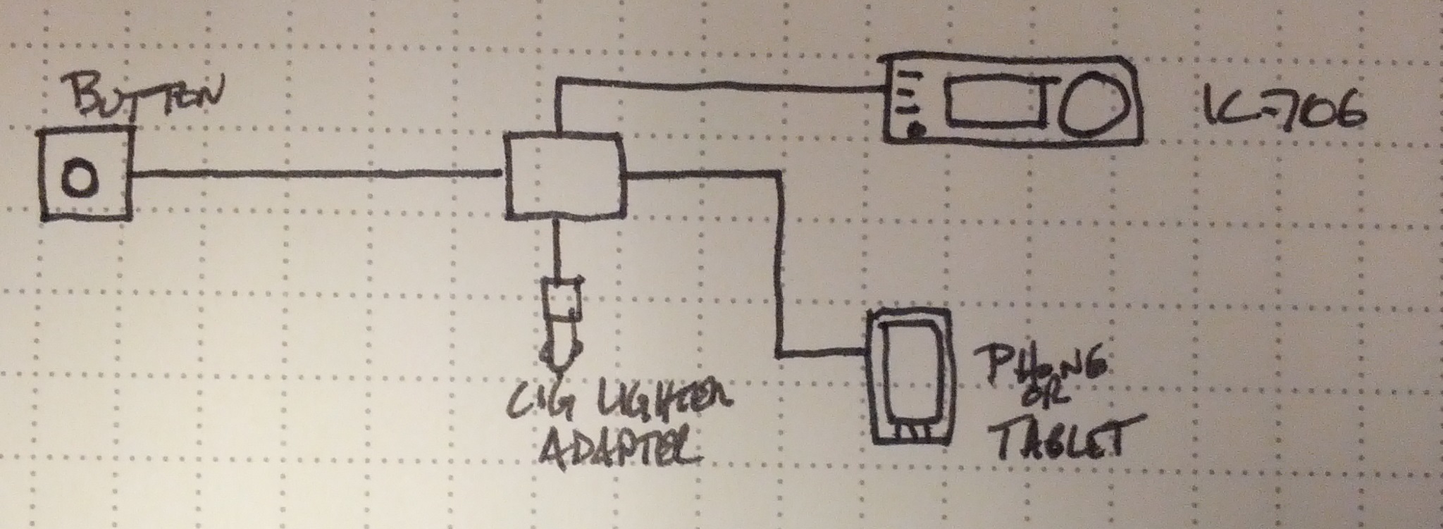
Easy button block diagram
So, an Easy Button. Ultimately, this will become an Android App. It’ll probably be Arduino powered. It’ll likely be open source, too.
I figure when it is plugged in, it should start an app (maybe I’ll have to do this manually). It’ll charge the Android device (hence the cigarette lighter adapter). It may run the GPS to get location when the button is pressed (I can think of a few uses for that); it would definitely get the time and date (UTC, of course!) from the phone, and it would prompt the phone to record the callsign, signal reports, and any other notes. It would also connect to my IC-706 to get the frequency and mode.
Stay tuned!
-73-
I spent the weekend building stuff.
RF Probe
First, I built an RF probe using a schematic from the ARRL Handbook. It’s a pretty simple build, as all I needed was a pair of old test probes, a germanium diode, a capacitor, and a resistor. I packaged the electronics in a small piece of CPVC pipe, which is nice and unobtrusive.
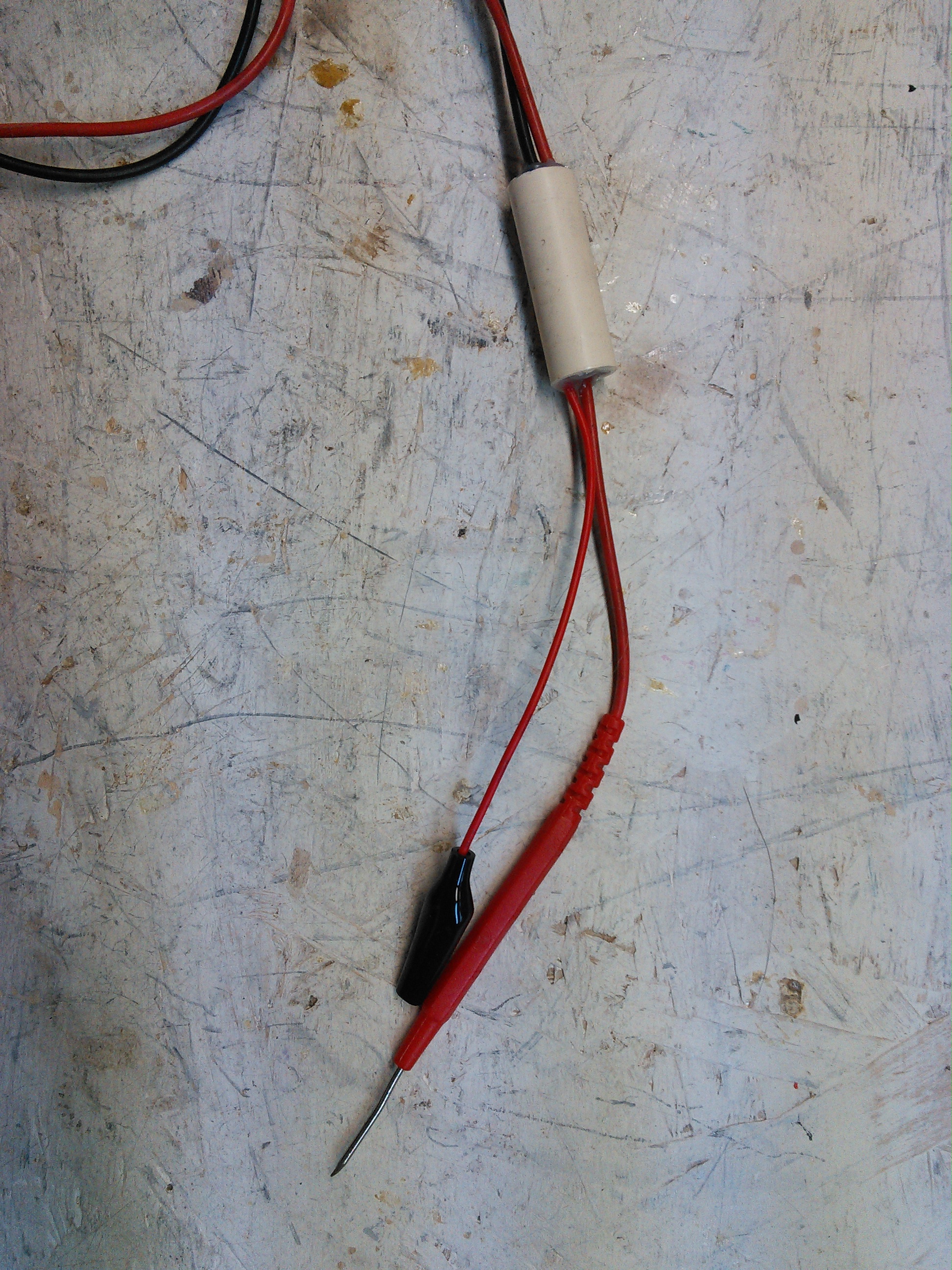
This is the RF Probe. It fits nicely in some 1/2″ CPVC pipe.
End Fed #2
After W0EA told me I used the wrong coil core material, I built one with the correct material (ferrite, not iron). I still have the old, so I’ll do some comparisons, but barring any major issues, I’ll stick with the ferrite one.
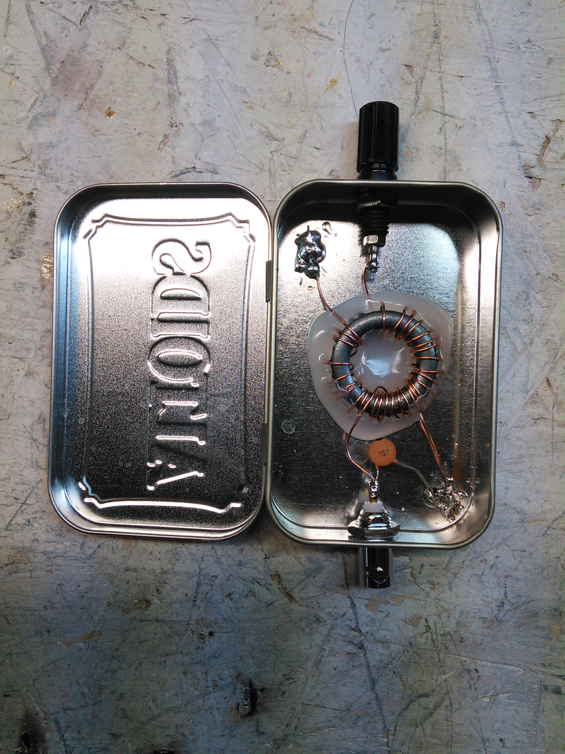
End Fed #2.
-73-
I don’t have much to post, and with weekends being nearly as busy as weekdays, I haven’t had much time to get into anything, but I did get some time working in the shack on a Par style end fed antenna. I started thinking about this and worked off the design on W0EA’s blog.
This is the inside of the box. I used an Altoids tin. The coil wire is small enough that I would consider this QRP only.
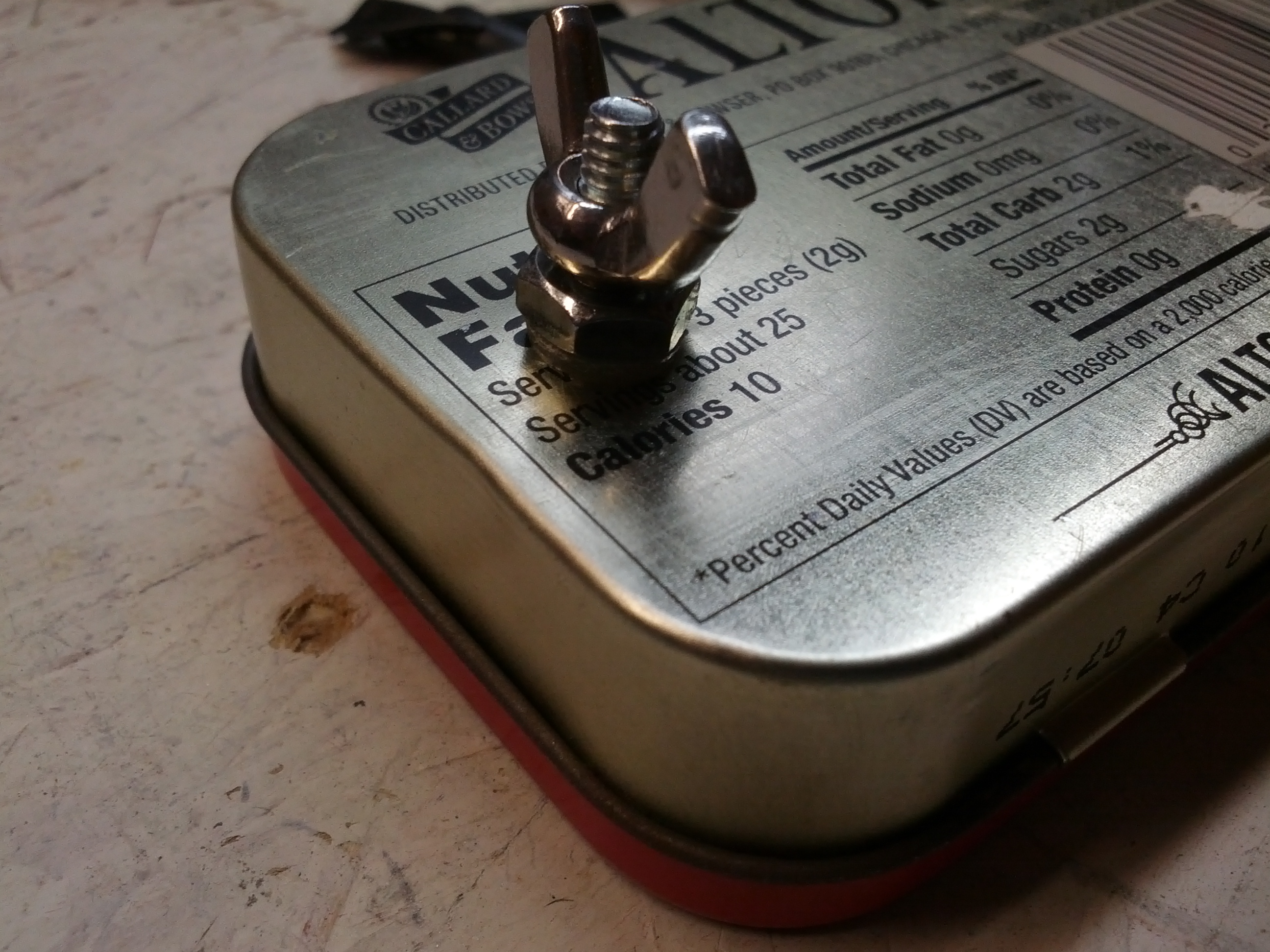
This is the back of the matchbox. It is difficult to tell in this picture, but the bolt is insulated from the case. At some point, I will improve this to have an insulated connector (right now, a good tug may cause the bolt to contact the case).
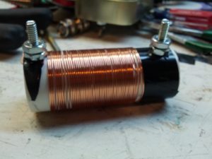
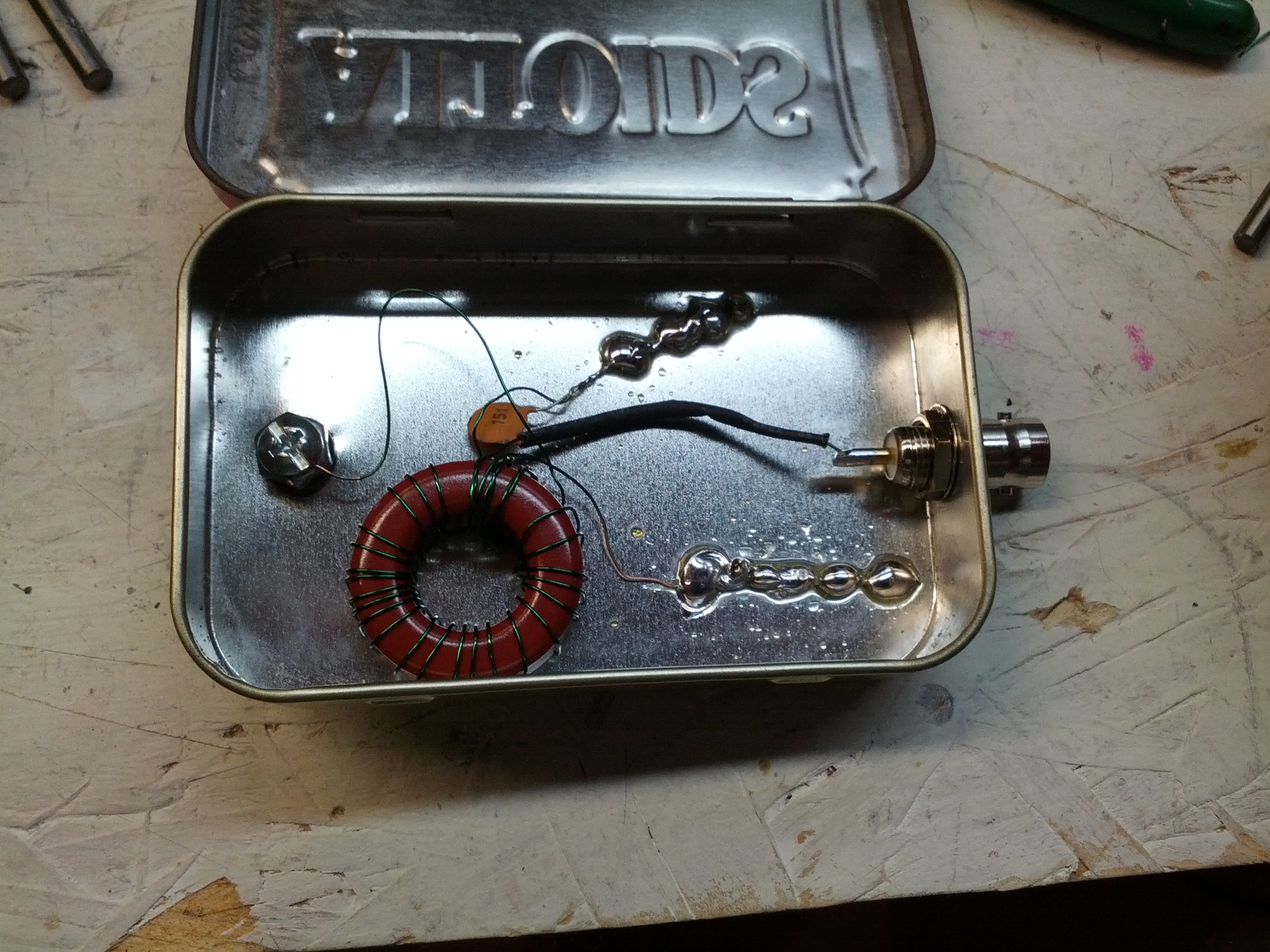
Soon to be trap. And for the love of all that is holy, DO NOT COUNT THE TURNS. It isn’t done, and I was adding turns when I should have been removing – this coil resonates on 10m, not 20m like I need.
-73-
UPDATE: W0EA connected with me via twitter to tell me I’m doing it wrong. Specifically, I should be using a ferrite core, not an iron core. Looks like I’ll be winding a new coil this weekend.
Over the long weekend, one of the many things I got done was the Ten Tec. I found that there was a wire that was disconnected from the antenna. Once I resoldered it, I was able to hear on 75 meters (it was 1:30 AM, so the other bands were pretty dead).

I did notice that the RIT control is a little off, but since I never seem to use it, I’m not particularly worried about recalibrating it.
I also need to build a tuner. I’ll probably build it, I’m just stuck between a T network or a Pi network. Either would be simple to build.
-73-
The finals are replaced and tested! 110 watts out!
So I started looking over things. One thing I’ve been looking into is the zero beat. It seems to me that when you push the button, it should emit the CW tone. I can get it to emit the tone, but only after pressing the zero beat button many times.
I also don’t like the CW tone. It seems odd even when at the correct frequency. I hooked up the audio output to my oscilloscope and saw the audio output… It looks…er…interesting.
I think I was expecting to see more of a sine wave as opposed to a sawtooth (I guess) wave.
There is one minor little problem – it appears the antenna isn’t properly connected to the receive part of the circuit, because it can’t hear anything. It does transmit on the correct frequency (per my antenna analyzer), so the problem is likely minor as opposed to something going bad related to the frequency or mixer.
This still feels like yesterday’s repair, even though it was tonight when I did all this.
Since I had the final module out from yesterday, I hooked power to it to test. I first tried the driver, and it didn’t trip the circuit breaker. Then I tried the high power amp and it tripped the circuit breaker immediately. Fearing the worst, I embarked on the long process of removing the finals (which was not fun because of how they were stuffed in there.
Finals in their copper case. Getting the heatsink off wasn’t too difficult, but getting the circuit board out of the copper was a pain.
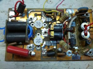
After a lot of work with a heatgun and soldering iron and wick and a bulb, I got this out.
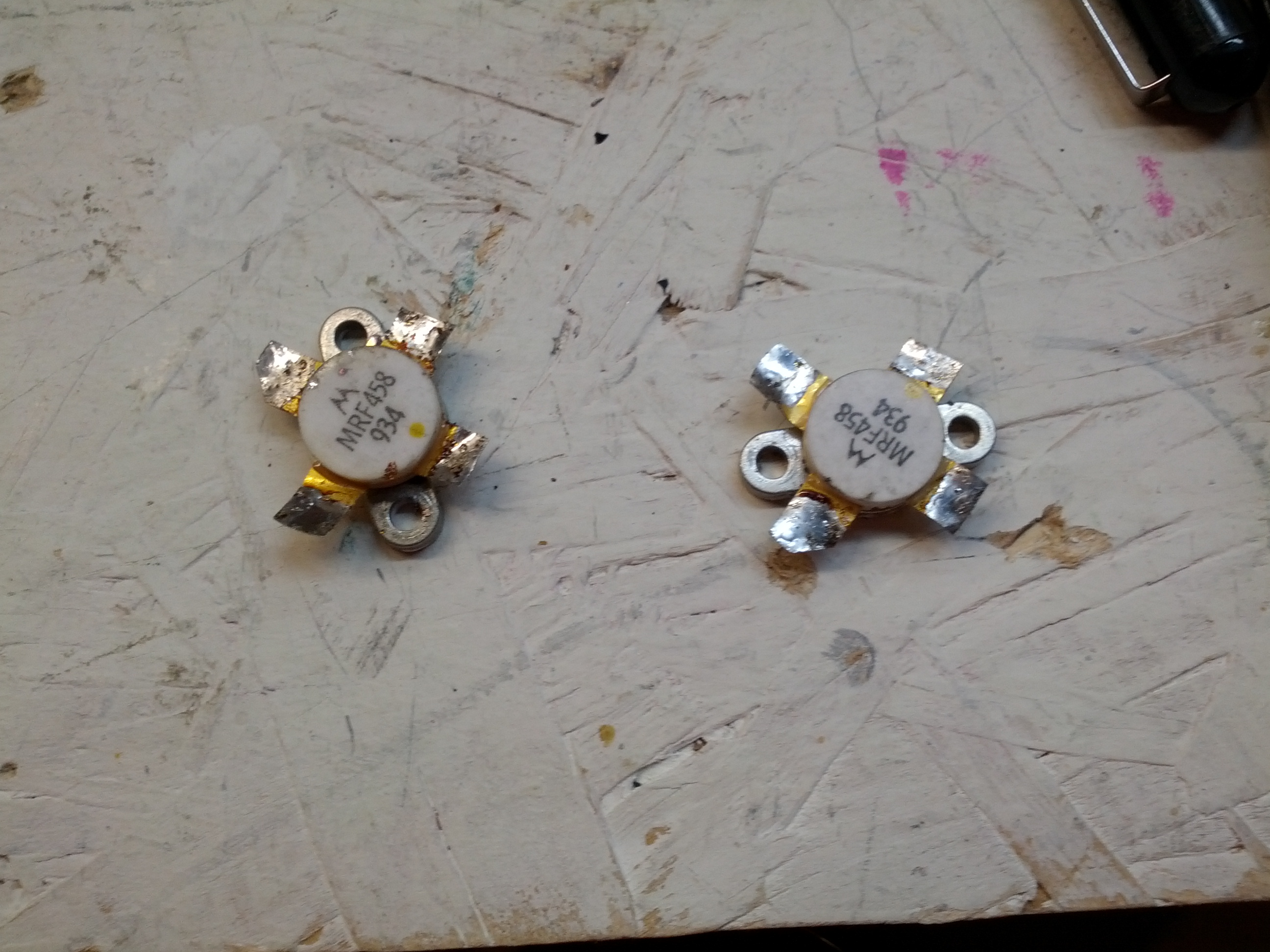
These are the finals after being removed.
So after removing these, I put them on an octopus tester, and tested them. The results are interesting. It also says that one or both of them is likely bad. These things aren’t cheap, but with how much of a pain it is to remove them, the smart thing would be to replace both, since one went, the other is likely not far behind.
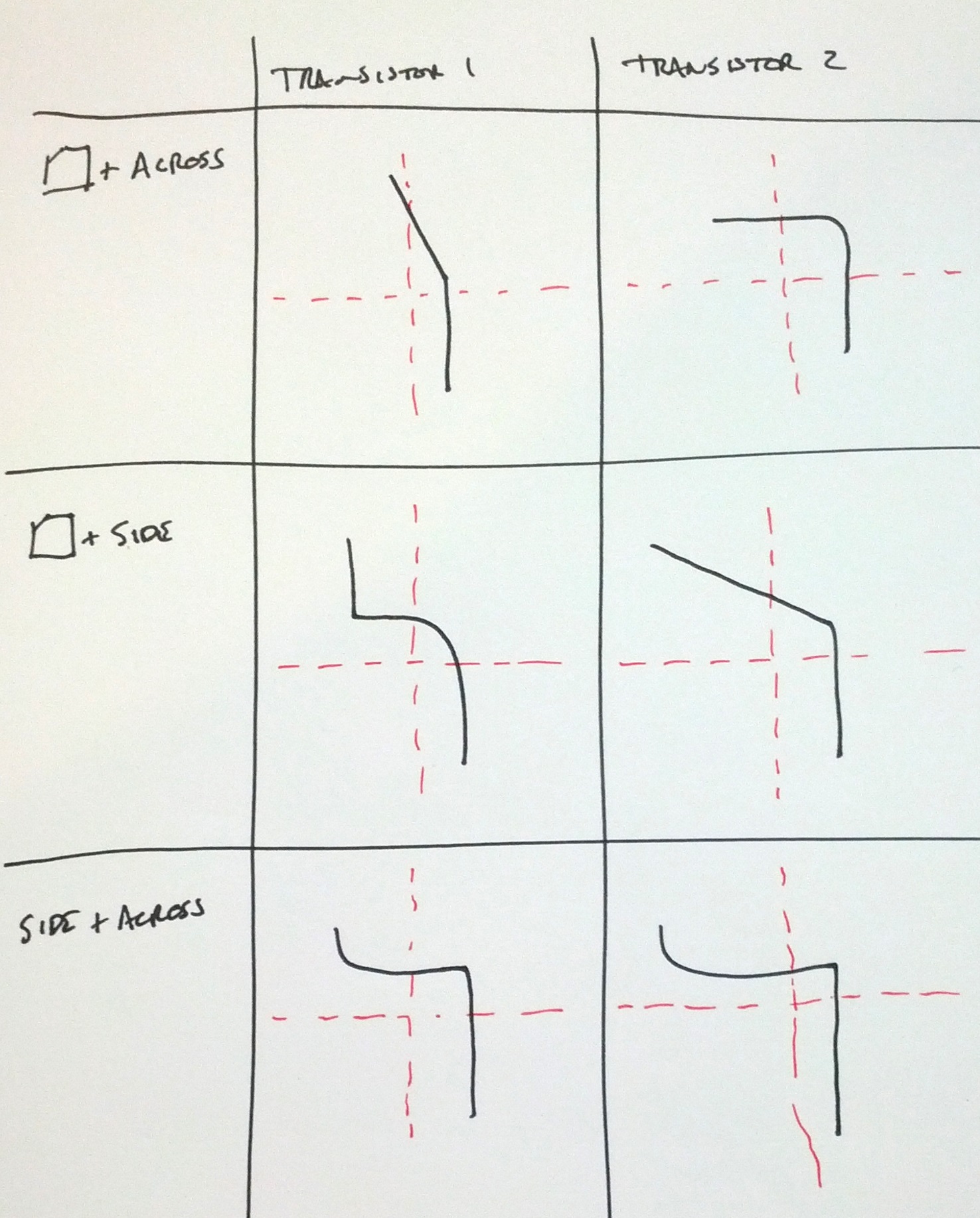
Note: the upper-left and middle-right are nowhere near the same:
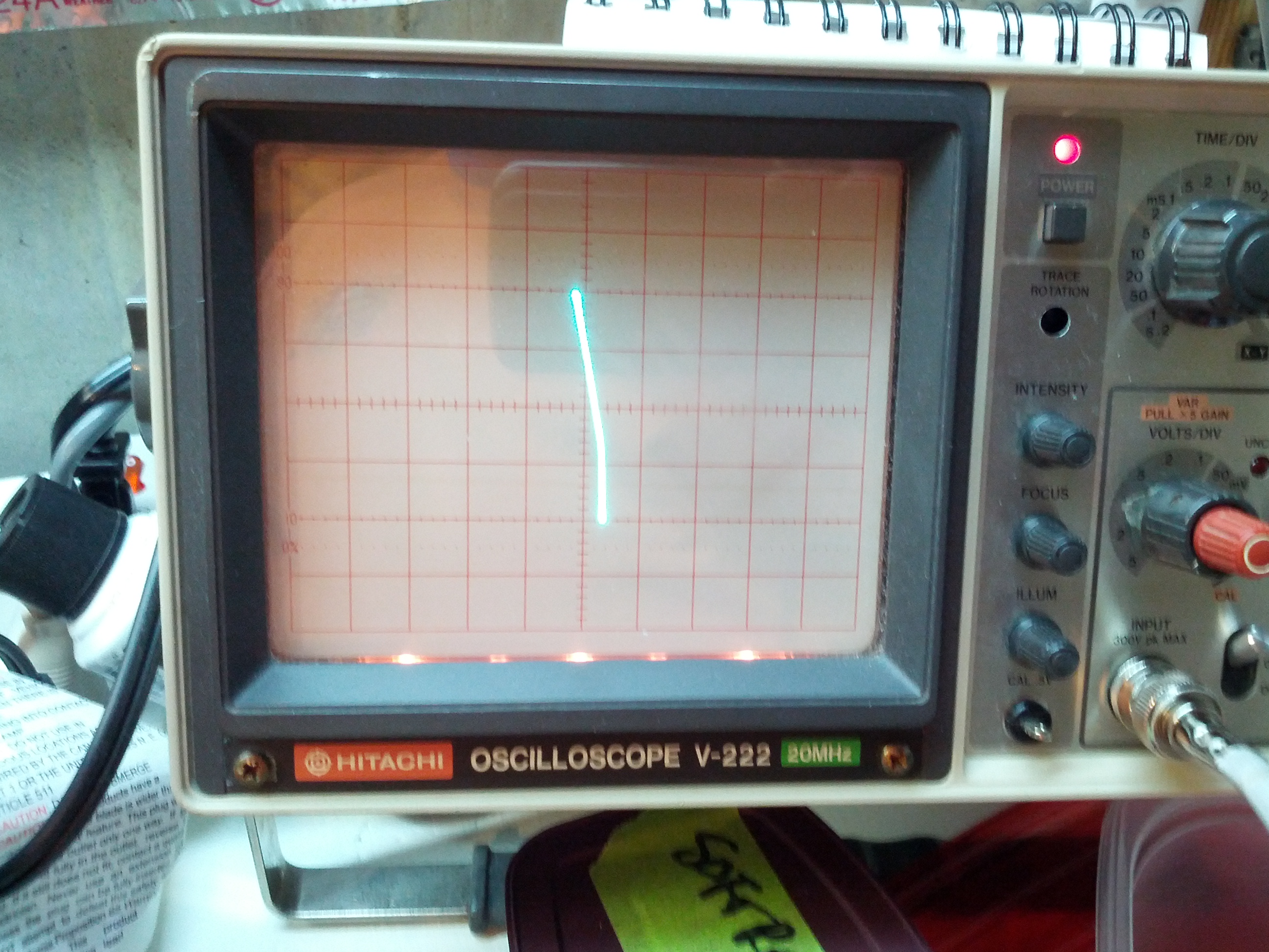
Upper Left
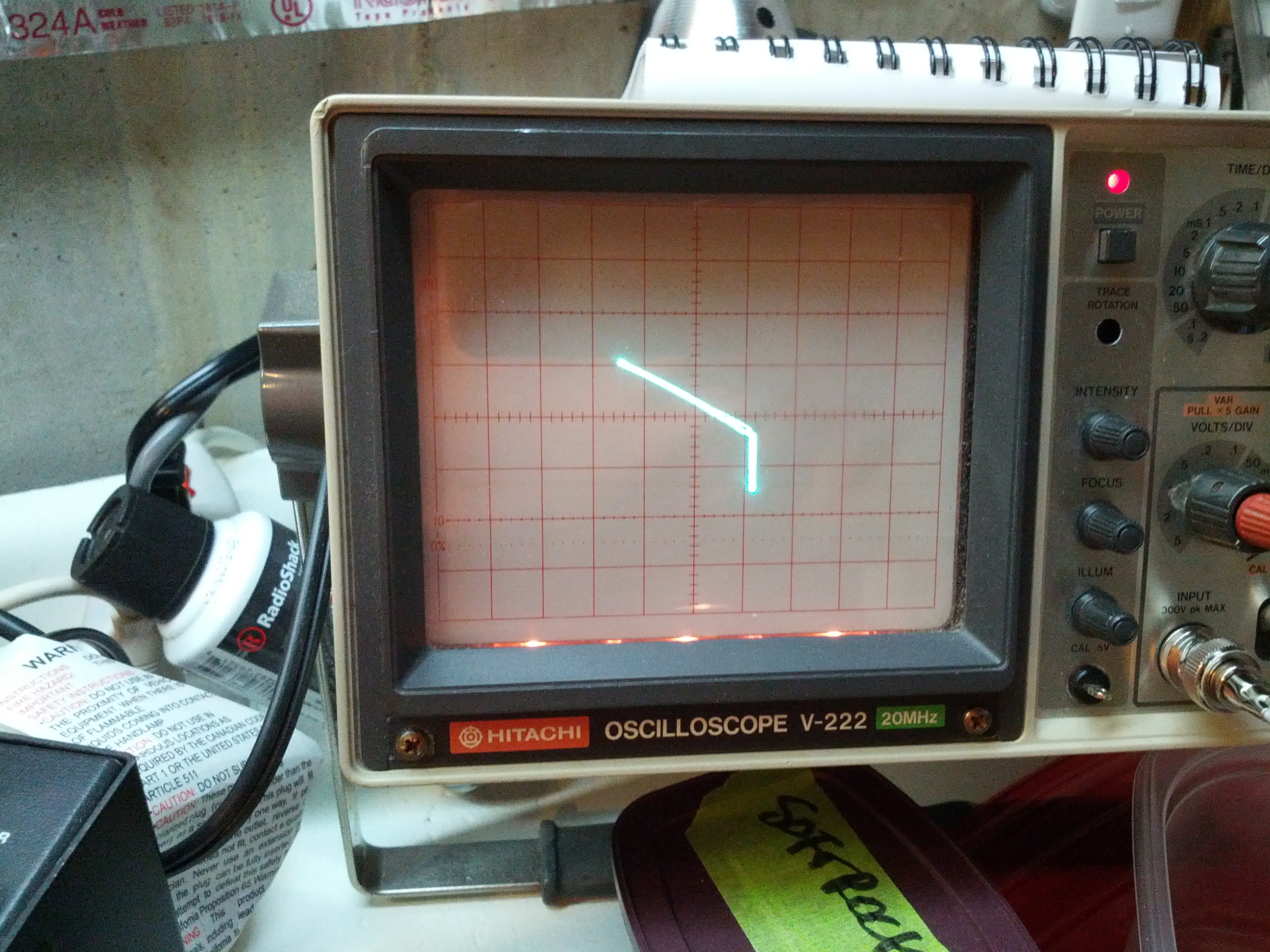
Middle right
Next up: replacing the transistors and powering the unit back on!
-73-
So after spending last weekend looking over things, I put everything back EXCEPT the finals and the speaker. I rigged a little power cord with alligator clips (I don’t have another plug for this radio) and a circuit breaker on the hot line. I connected the hot to the fuse in the radio and the ground to the radio chassis and powered up the supply. I was greeted with the radio lighting up 21.2027 MHz. I couldn’t hear anything, as I had the speaker removed.

So the next thing I did was resolder the speaker and the the finals. After finding a nylon washer for the internal hot wire in the finals, I did the minimum replacement of screws and powered the unit back up. It immediately popped the circuit breaker.
Guessing that the finals were bad, I removed the finals and powered the rig back up. The display came back up, but no sound out of the speaker. I started adjusting the volume and RF gain trying to hear something. I then noticed that the mode switch was set to “LOCK”, so the transmitter was on. One thing I did notice is that no power was coming out – I had the internal antenna connection connected to my little QRP dummy load that has a rectifier output and I had my multimeter connected to it and there was no DC voltage coming through the dummy load and no read on the frequency counter in my antenna analyzer.
While there is a slight flaw in my troubleshooting, I’m fairly confident that the problem is the finals and I will be taking a closer look at the module tomorrow.
Incidentally, I looked up the price for new finals at RF Parts. $60 for a pair, and $25 for one. Of that’s the problem, it’ll be a fairly inexpensive fix.
I recently acquired two additional antennas and decided to tune and test them. So I pulled my truck out on the driveway, put the correct ferrite onto the antenna wire, and plugged in the antenna analyzer.
The reason why I saw the SWR go through the roof was because it WAS through the roof. I was able to, with some difficulties, get three of the four antennas tuned. Mind you, tuning these hamsticks is a little bit of voodoo magic mixed with luck and perseverance (in other words, they’re a pain in the ass). The untuned one is 40 meters. The biggest pain was the 6 meter antenna (I had to cut it back because only a few inches of the stinger needed to be out.
There is a problem. I can’t put any of these on my truck and pull into the garage. I do want to move the mount, and once I do that, the 6 meter antenna would be able to stay on the mount, and I’d have to switch others.
See you on HF!
-73-
For those that do know me in real life, I’m not an electrical engineer, I’m a traffic engineer (more specifically, I do traffic forecasting, which also makes me somewhat of a programmer and a transportation planner). I can build electrical things when they’re easy or when there’s a schematic.
For those that have been following this blog, I just put my only real* HF rig in my truck.
For those of you that have been following me on Twitter and have a damn good memory, you may remember my first rig was a Ten Tec Omni.
So enter my issue. I have a broken (but otherwise great) rig at home, I’m too cheap to send it to Ten Tec**, and I want to learn more about repairing my equipment. This is a lot harder than Arduinos and Raspberry Pis and Beagle Bones!
The Transceiver
The transceiver is a Ten Tec Omni C Model 546. It has all the options – three crystal filters (2.4 KHz, 1.8 KHz, and 500 Hz) and three audio filters (10 KHz, 500 Hz, and 150 Hz of audio) PLUS the WARC band (12 meter and 17 meter) crystals installed.
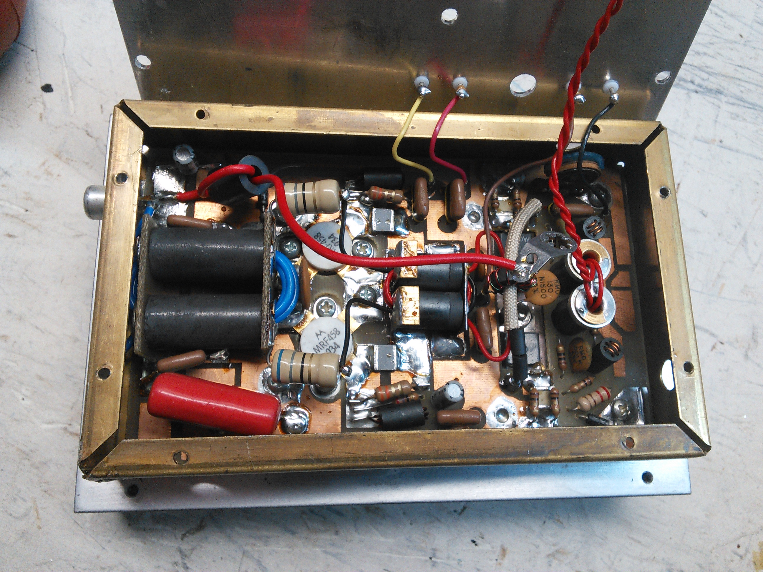
The guts of the rig are modules – each plugs into the chassis.
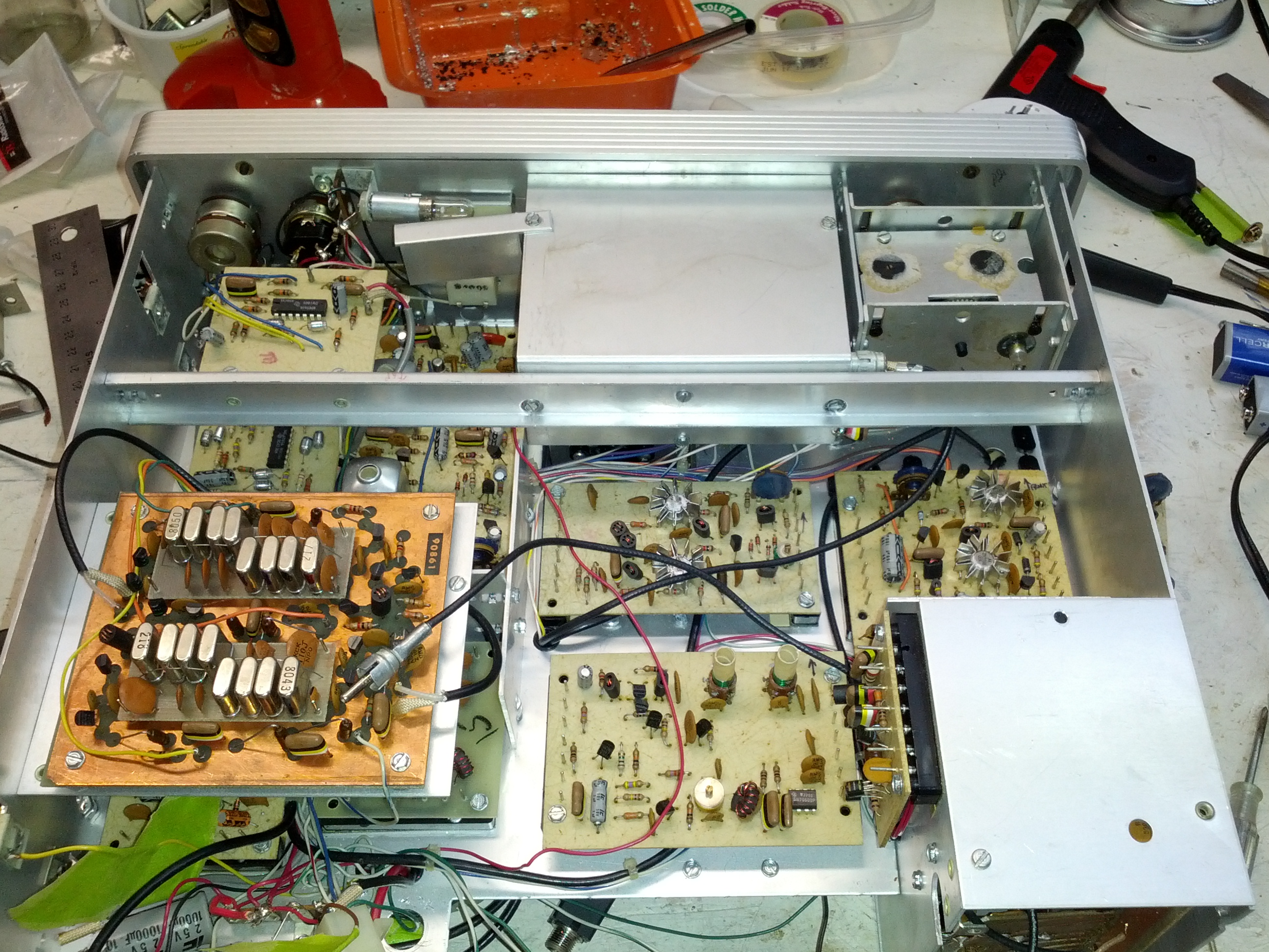
These are the guts of the Omni C. Note the modules, each of these can be removed pretty easily.
The Problem
While running around 25 watts out on the NAQP RTTY contest a few years ago, the rig and power supply died mid-transmission. I tried throwing the switch off then on, and the I saw the lights (the meter and the frequency display) light up and immediately die.
I tested the power supply, and it has 13.8 volts out.
I put an ohmmeter on the rig’s power connectors and saw very low ohms (something like 200 ohms). Seems to me that a part failed and opened a path to ground. With that thought in mind, I did check the 1 uF capacitor and the diode that connect between the +V in and ground (those seemed like the easy tests. I basically disconnected both from ground and tested the resistance betweren +V and GND and there was no change in resistance. However, the rig is modular, and there are dozens of places where there is a capacitor between a +V and GND connection.
My Thoughts
One thing about this rig is that everything is modular. I can remove parts very easily and test the resistance to ground (which I’m guessing should be very high). So if I find something that has a low resistance to ground (in the ohms instead of kilo-ohms), I should probably start looking there.
One thing I did do is remove the meter light bulb and the resistance went up to 450 ohms. It seems to me that the resistance should be somewhere in the 10 kilo-ohm range, but again, I’m not an electrical engineer.
Reader Participation
Let me know in the comments, via twitter, Google+, or email – am I on the right track? Anyone have one of these and know of a common failure? I’ll gather a work-week’s worth of comments and do tests on the weekend (or through the week, if I have the time).