
Tag Archives: building
I’ve been reading a lot about receivers, and it sounds like one important thing is filtering. It makes sense too – simple receivers can suffer from front end overload due to a strong signal. And when on the ham bands, you never know where that strong signal may be – it could be someone driving down the road (which is a bit obvious once you see it), but in my neighborhood, if you don’t know me, you’re probably not going to know about the antennas in my attic.
I don’t have a spectrum analyzer, and since I’m a traffic engineer, I really don’t have access to one. I don’t need a full-blown spectrum analyzer, either, I just need to sweep through the HF band and get the difference between signal input and output. Math will take care of the rest.
$$dB=20*\log{\frac{V_{out}}{V_{in}}$$
The way I figure it is this:
An Arduino (and this could become a Raspberry Pi or any number of other devices, but I’m going to use an Arduino because it’s cheap and relatively durable) controls a direct digital synthesizer (DDS) module that just scans through it’s limits… well, probably something like 0.5 MHz – 40 MHz – that gets me into the AM broadcast band (which can be a source of strong signals) to above the 10m band (I don’t know what’s up there, but whatever’s there is probably not running 50,000 watts).
The output of the DDS would have an RF voltmeter and a probe to go to a filter. There would be another RF voltmeter to sense a filter output. The Arduino would handle not only control, of the DDS, but also sensing the voltage.
It’ll look something like this:
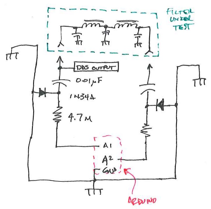
This is a block diagram/schematic of how this will work. I didn’t include the DDS module, which would be tied in there somewhere.
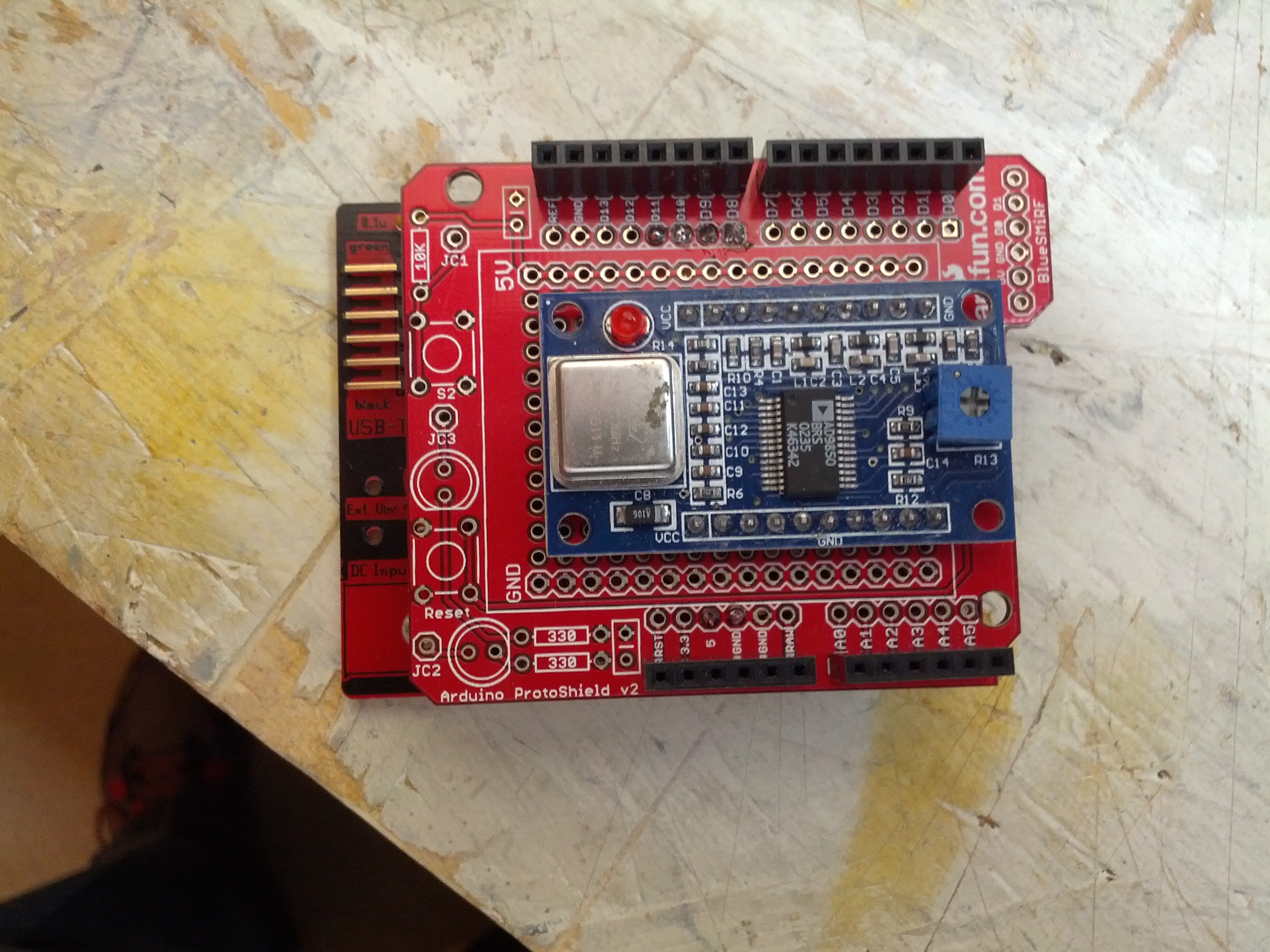
The Arduino and DDS will look like this:
There will have to be a companion app to this. In Java (not just because I’m drinking coffee, but also because it’s cross-platform). It’ll look like this:
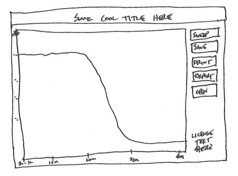
This is likely how things would look. Simple. A button that tells the Arduino to sweep, and some other important buttons.
I have the perfect item to test with also. One thing I built and don’t use (and never truly finished) was my Softrock RXTX. I need to build a filter for the output to keep the harmonic of the 7 Mhz fundamental from being too strong on the 20 meter band. I wound the coils while watching the Super Bowl-over-the-Broncos and printed a circuit board just before the game started.
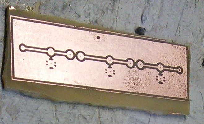
Easy and small, but for 0.95 Watts, you don’t really need much.
I’m not really sure if this will work, but it certainly seems like it would, and I think it would be interesting to see how some filters respond on this compared to a real spectrum analyzer.
-73-
If you look back into a few of my past pictures, like this:
The bottom of the board
You can see a bit of glare on the board. Sometimes it’s bad, sometimes it isn’t. Most of the time, I see it and move the camera to NOT show really bad glare. This is caused by the florescent lights above my workbench. I needed to get a picture of another board, and the glare was worse than above. Since my cell phone (which tends to be my primary camera) needs the light, I decided to deal with the issue.
The way to deal with this is to use a diffusing disc to diffuse the florescent light and eliminate the glare, like in the diagram below.
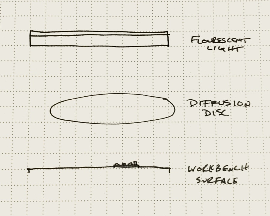
Diagram of arrangement you see in the image below.
And yes, you can hold this with one hand, take a picture with the other hand…
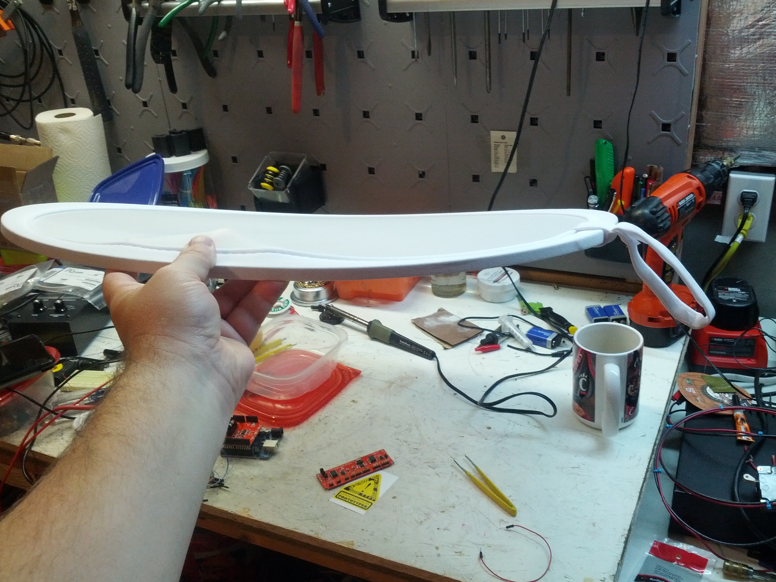
I think I spent $25+ on my diffusing disc at a specialty camera store. However, I’m fairly sure it is no better than the $12 one at Amazon. Additionally, I could use a clip light to put more light on the workbench and still eliminate the glare. The point of the diffusing disc is to scatter the light.
Using this diffusing disc, the glare reduction is pretty obvious in this more recent image:
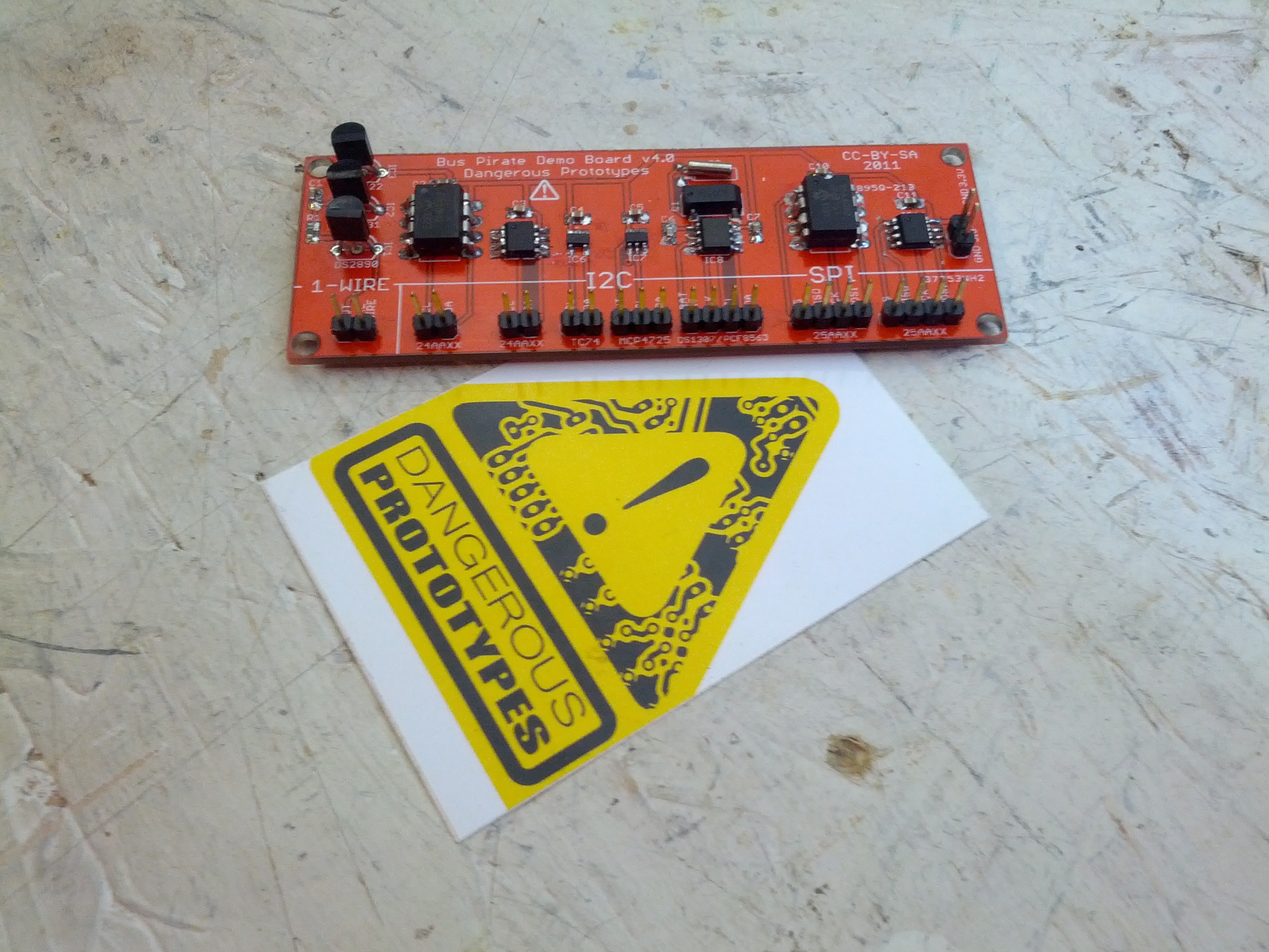
Look ma, no glare!
I spent the weekend building stuff.
RF Probe
First, I built an RF probe using a schematic from the ARRL Handbook. It’s a pretty simple build, as all I needed was a pair of old test probes, a germanium diode, a capacitor, and a resistor. I packaged the electronics in a small piece of CPVC pipe, which is nice and unobtrusive.
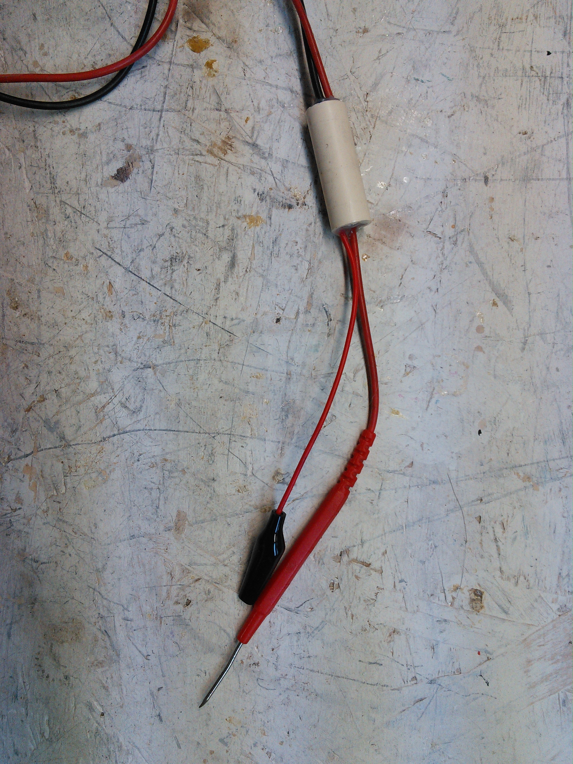
This is the RF Probe. It fits nicely in some 1/2″ CPVC pipe.
End Fed #2
After W0EA told me I used the wrong coil core material, I built one with the correct material (ferrite, not iron). I still have the old, so I’ll do some comparisons, but barring any major issues, I’ll stick with the ferrite one.
End Fed #2.
-73-
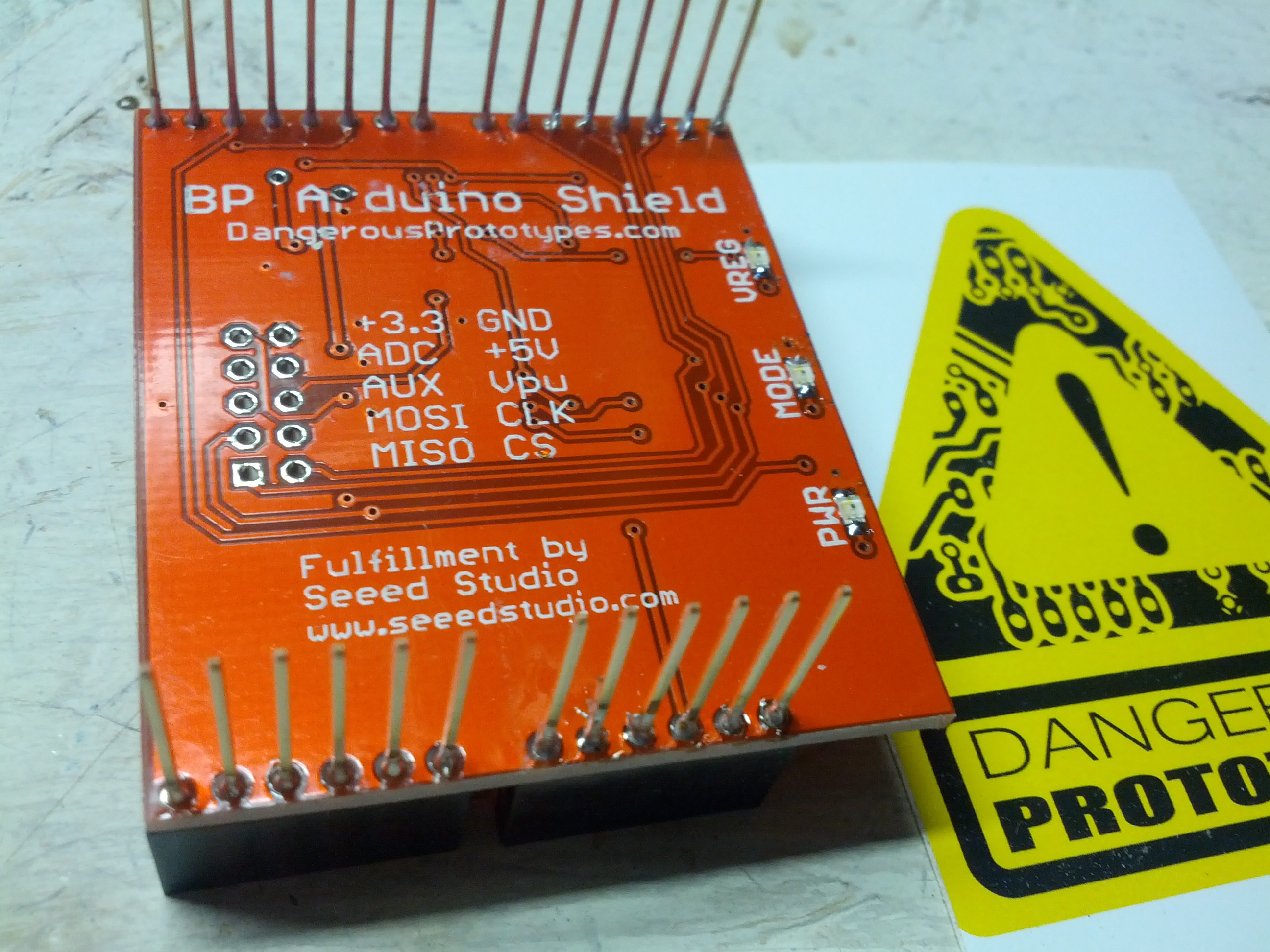
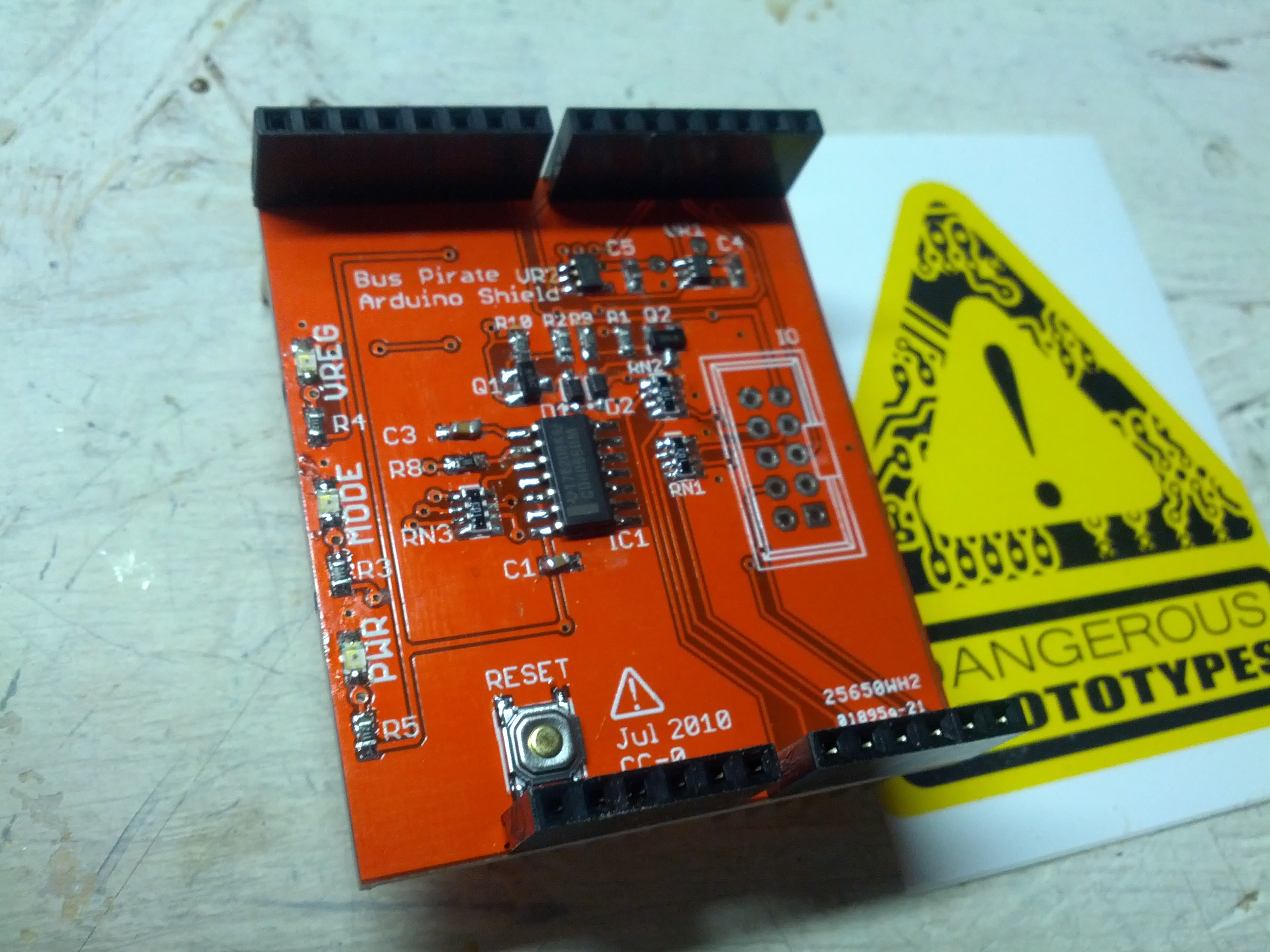
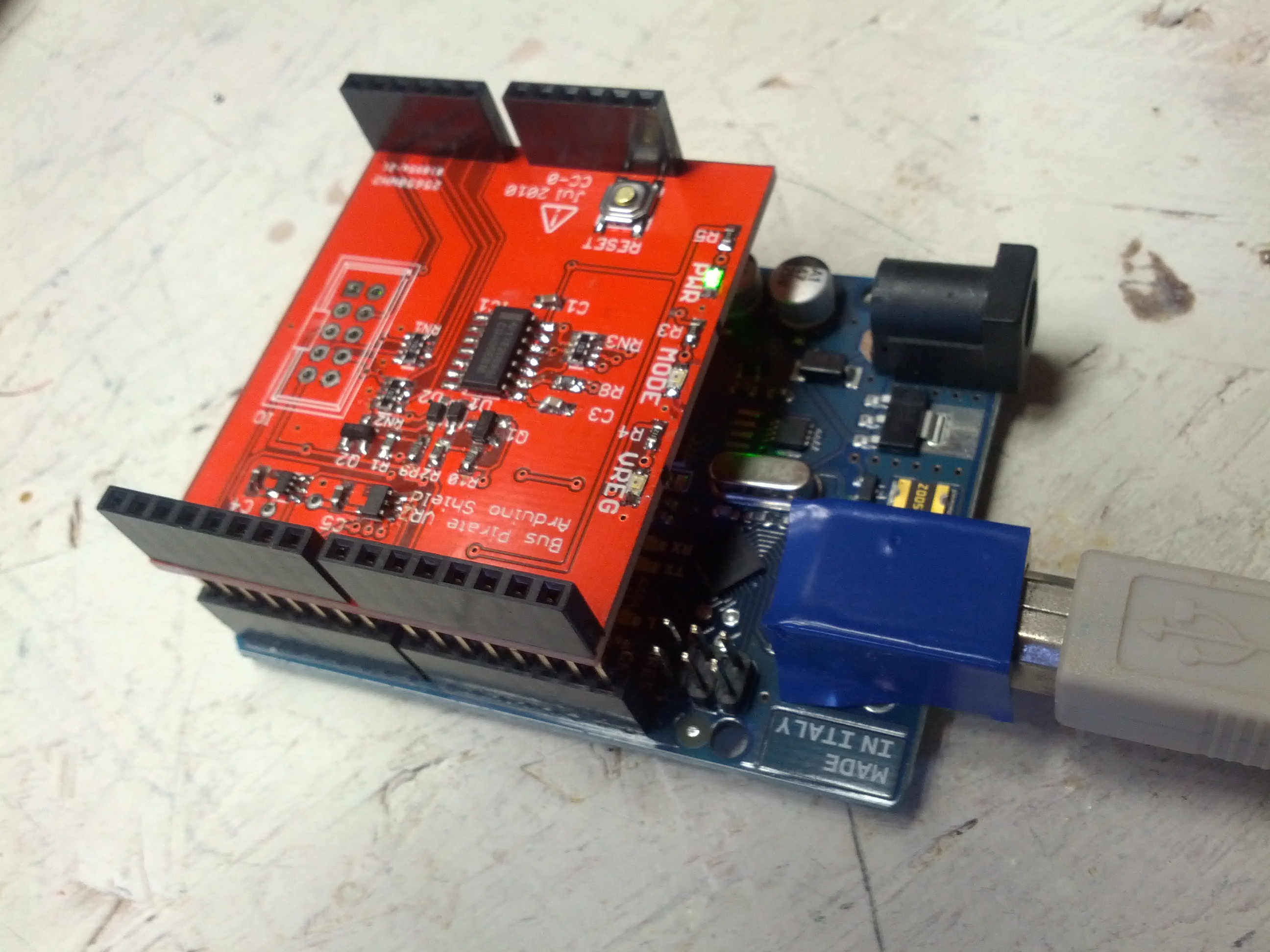
A few months ago I had the luck of winning a free PCB from Dangerous Prototypes via twitter. I finally got around to building it. Below are some pictures of the build. Please no comments on my soldering skills – I’m still a novice at SMD components. This is the second kit I’ve done with SMD components, and the other was only a handful of SMDs and mostly through-hole.
There is one part missing – I didn’t install the connector for the test leads. I forgot to buy it when I bought the rest of the components (and it wasn’t actually the only thing I forgot).
-
- The top of the board
-
- The bottom of the board

-
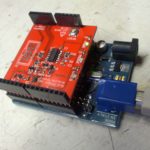
- The top while attached to an Uno. I did use different LED colors (green for power, and yellow for mode and voltage regulation).
This was a fun build, but it did underscore my need for a new soldering iron for SMD items and a new tip for my general purpose soldering iron (which is really too hot for SMD, but so far I haven’t burned anything up).
Now all I need to do is figure out how to use this thing! 🙂
-73-
This post is about the recently-built and the to-be-built projects I’ve been working on.
Recently Built: RF Sampler
First off, the recently-built. I recently built an RF Sampler. This little device allows me to connect a rig under test to my oscilloscope. The schematic is quite simple, as it is basically a voltage divider that divides the voltage between an internal resistor and a dummy load. Below are the pictures.
And what are pictures without a video to show it works?
The schematic for this is at http://www.qsl.net/k6ls/rfsampler.html. Also note this video from W2AEW (which is an expanded design of this).
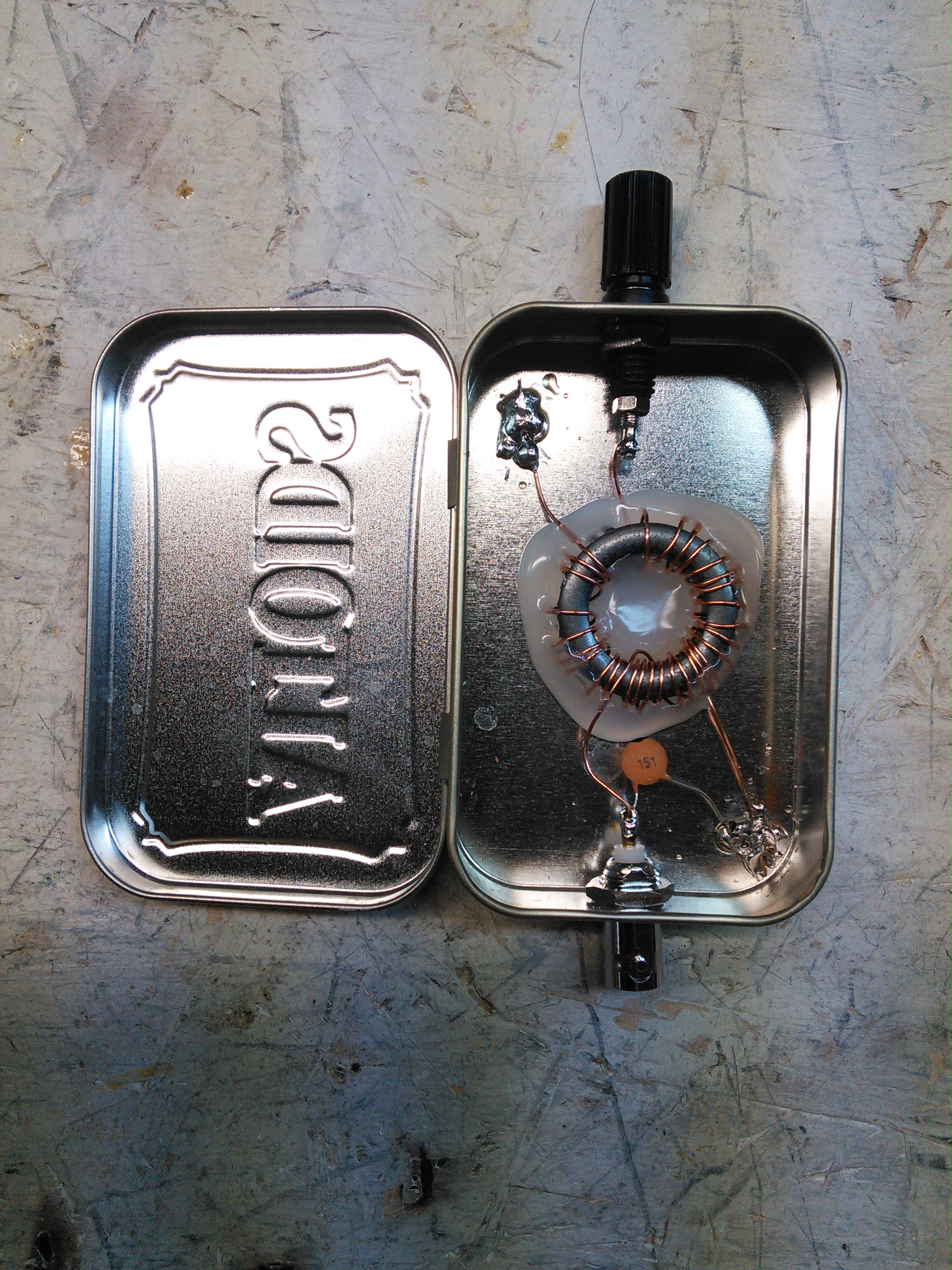
Recently Built: Octopus Tester
Another item I recently built is an octopus component tester. This is a simple tester that makes some basic tests on electrical components, like capacitors. You can’t get the value of capacitance (etc) from this, but you can see if it works by hooking it up to the tester and checking it on an oscilloscope. I built this into an Altoids tin.

Below is what a capacitor looks like on the scope.

More information on this can be seen on W2AEW’s video.
In The Pipeline
I have one item in the pipeline, maybe two.
One of them is a Time Domain Reflectometer. There are schematics for that in the ARRL Handbook. This would help me test coax. I may jump to an Arduino-based pulse generator first.
-73-