
Category Archives: Equipment
This past Saturday, I went to the Columbus hamfest and ARRL Great Lakes Section Conference. It was a disappointingly small hamfest for being on the NE side of the second-largest city in Ohio (full disclosure: that’s CITY population, regional population puts them third, behind both Cleveland and Cincinnati). I think I spent one hour there and about $40, including admission.
On my way out, I stuck my 10m hamstick on the truck. I knew there was a QSO party on 10, so I thought I’d jump on while driving. I figured I’d check the antenna (which I’ve never tuned). I set the rig to low power and CW and pushed the mic button. SWR was great.
Fearing that such a good SWR for a never-tested antenna was too good to be true and not hearing a CW tone, I set the rig to AM on low power to check. Same SWR reading. So I set the power to 2 (out of 10) and checked again. SWR through the roof. I contemplated going back in to buy another hamstick to get the small Allen wrench to adjust the stick, but decided that spending more money without a full understanding of the issue (and wondering if the problem was tuning or common mode current), I figured I would have been putting good money after bad and decided to leave and just listen on 10 on my way home until I got in the area of the repeater.
When I returned home (well, several hours after I returned home), I did a little bit of reading on the mobile HF oracle (k0bg’s website) and it confirmed my common mode suspicions. Looks like I need to get an order in for some mix 31 ferrite beads. I need to do some vehicle maintenance, so I may try to do all of it next weekend.
Additionally, I spoke with another local ham on the following Monday that gave me a few pointers courtesy of a friend with a 706, including to put a ferrite on the power leads and to make sure the bonding is done well – he had to strip paint to get a good bond.
So in the immortal words of K5PO from the Noise Blankers (who ironically has an Icom right in front of him and his name is eerily similar to mine)…

-73-
After reading Russ’s comment on last week’s post, I decided that he’s right. There’s no good reason to keep the FT-7800 in the truck when I’m installing a better, more capable radio. So it came out. Below are the gory details, all in pictures.
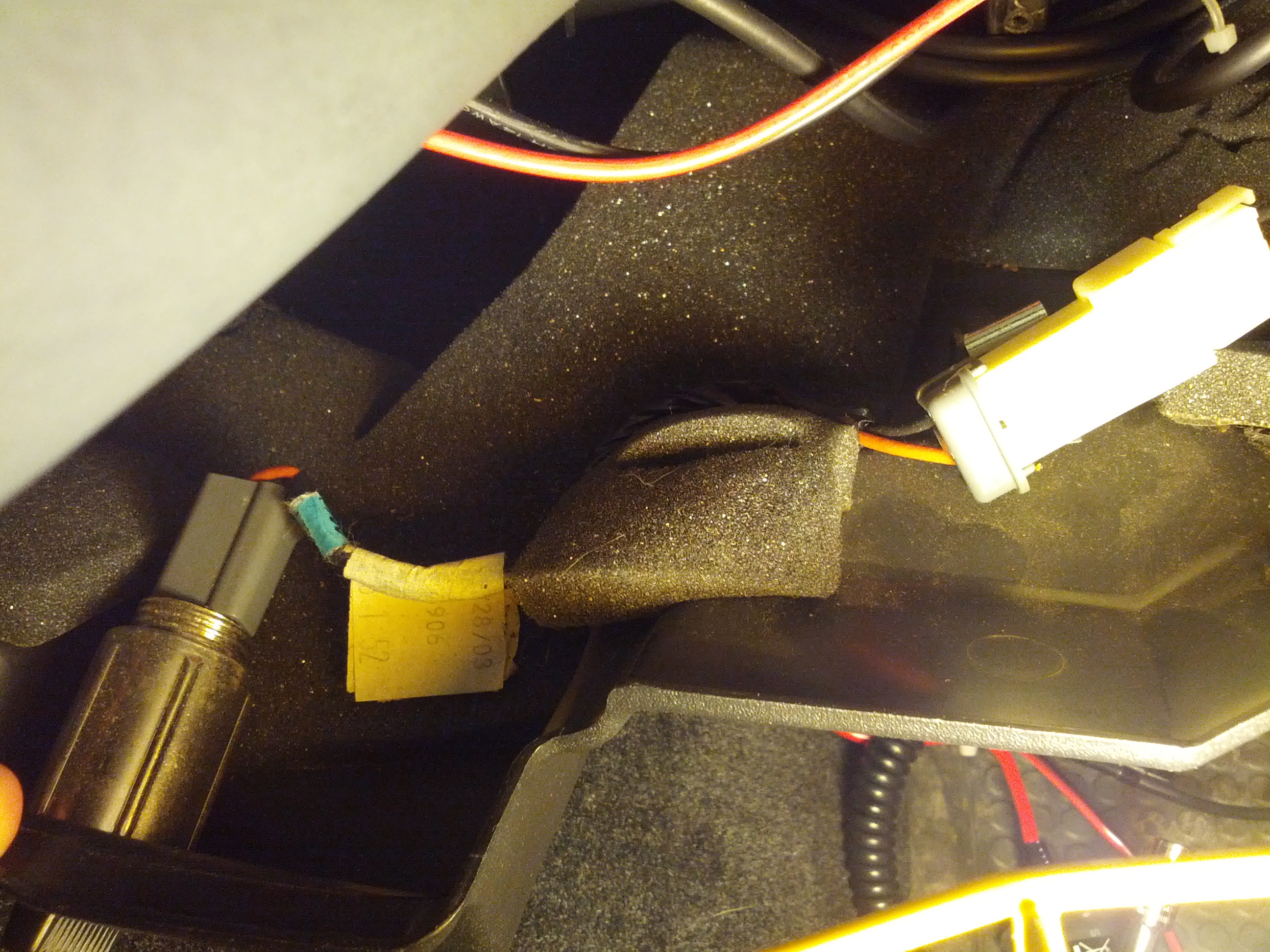
This is the reason why people like K0BG says on his website (which is the Oracle of Mobile HF) to NOT use cigarrette lighter wires – these things are around 16 gauge. Pulling 20 amps through this for an extended period of time would cause a fire.
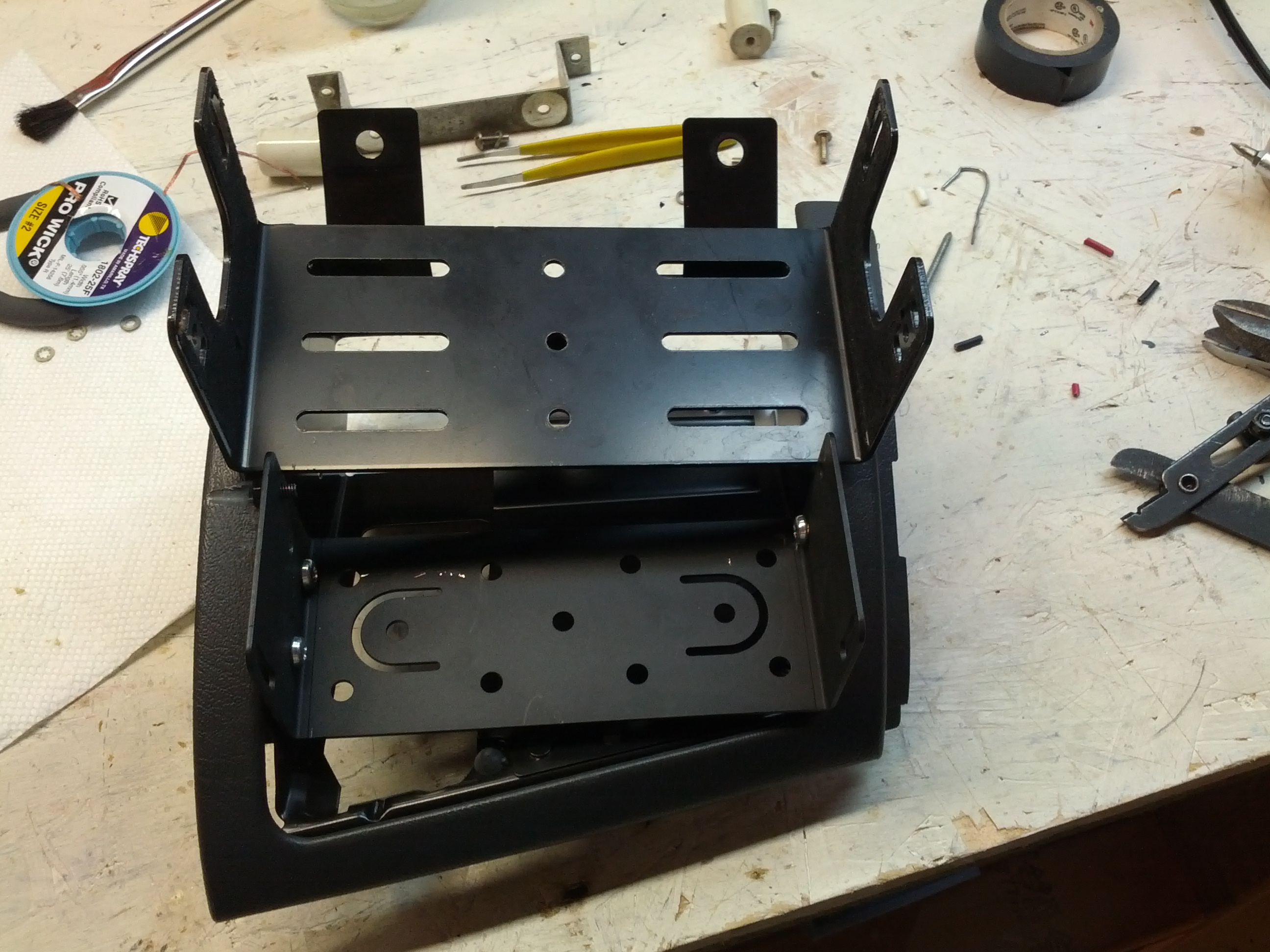
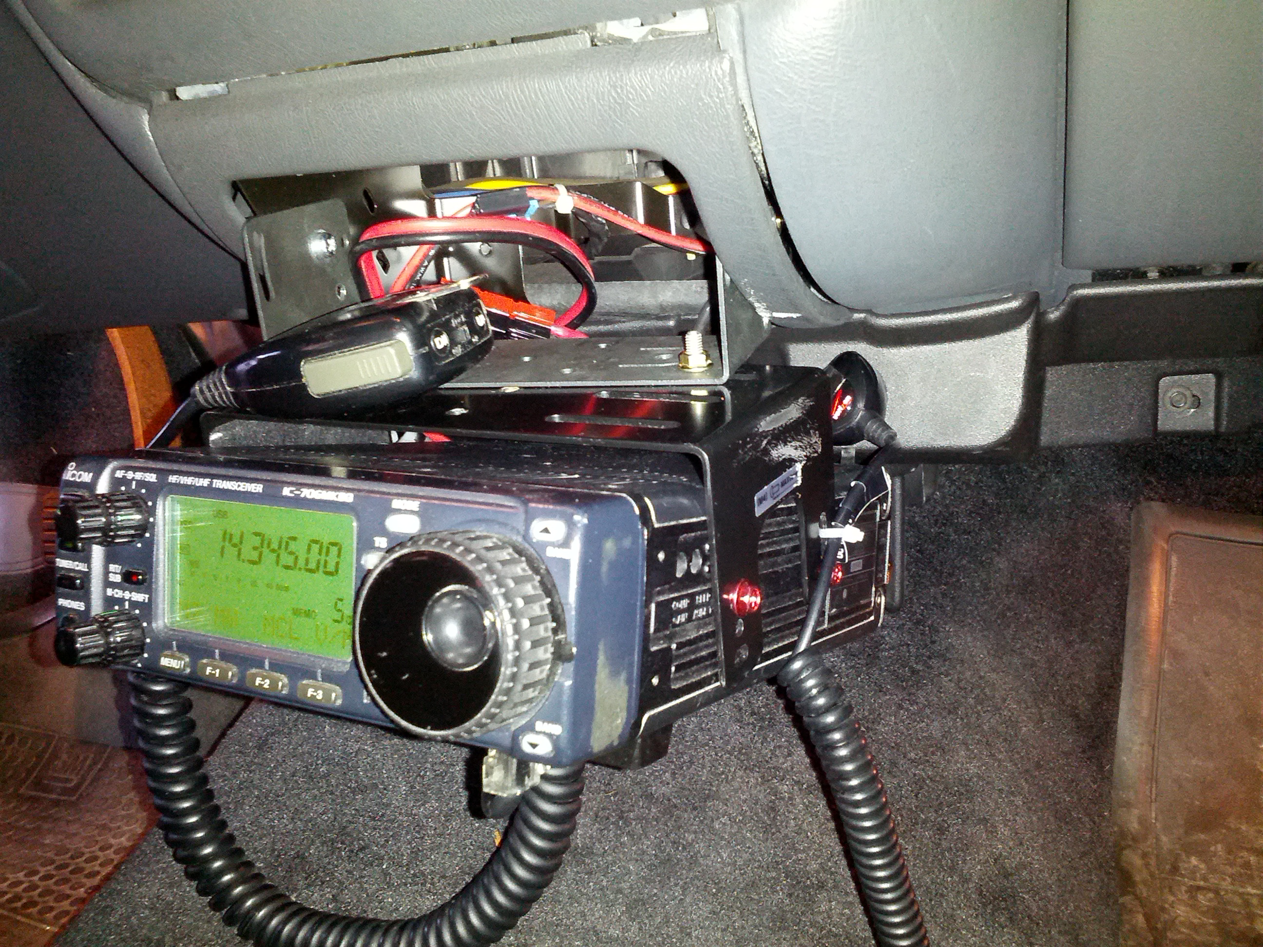
There’s a little problem with fitting this thing in…
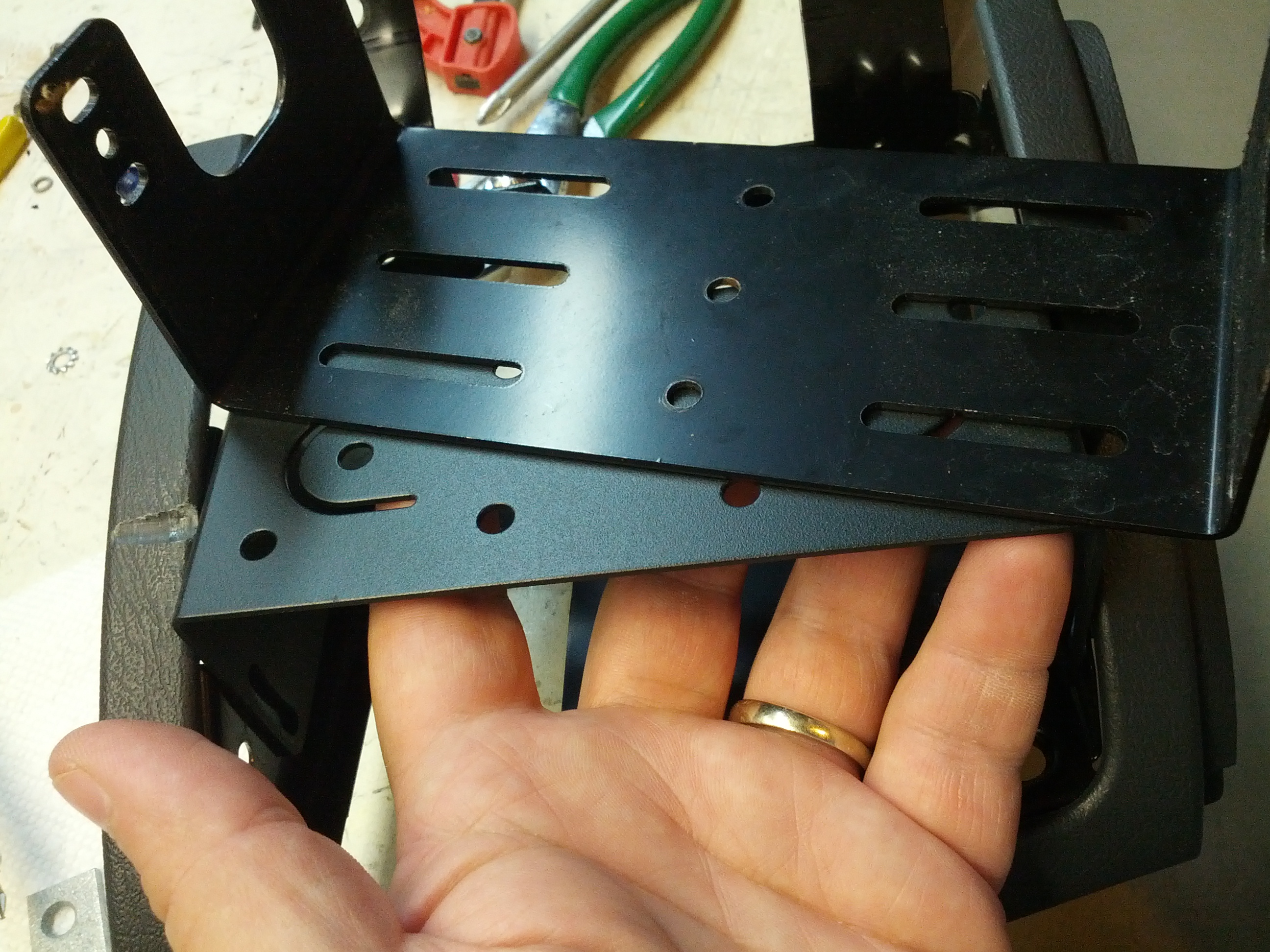
So if I turn this over and bolt it in upside-down…
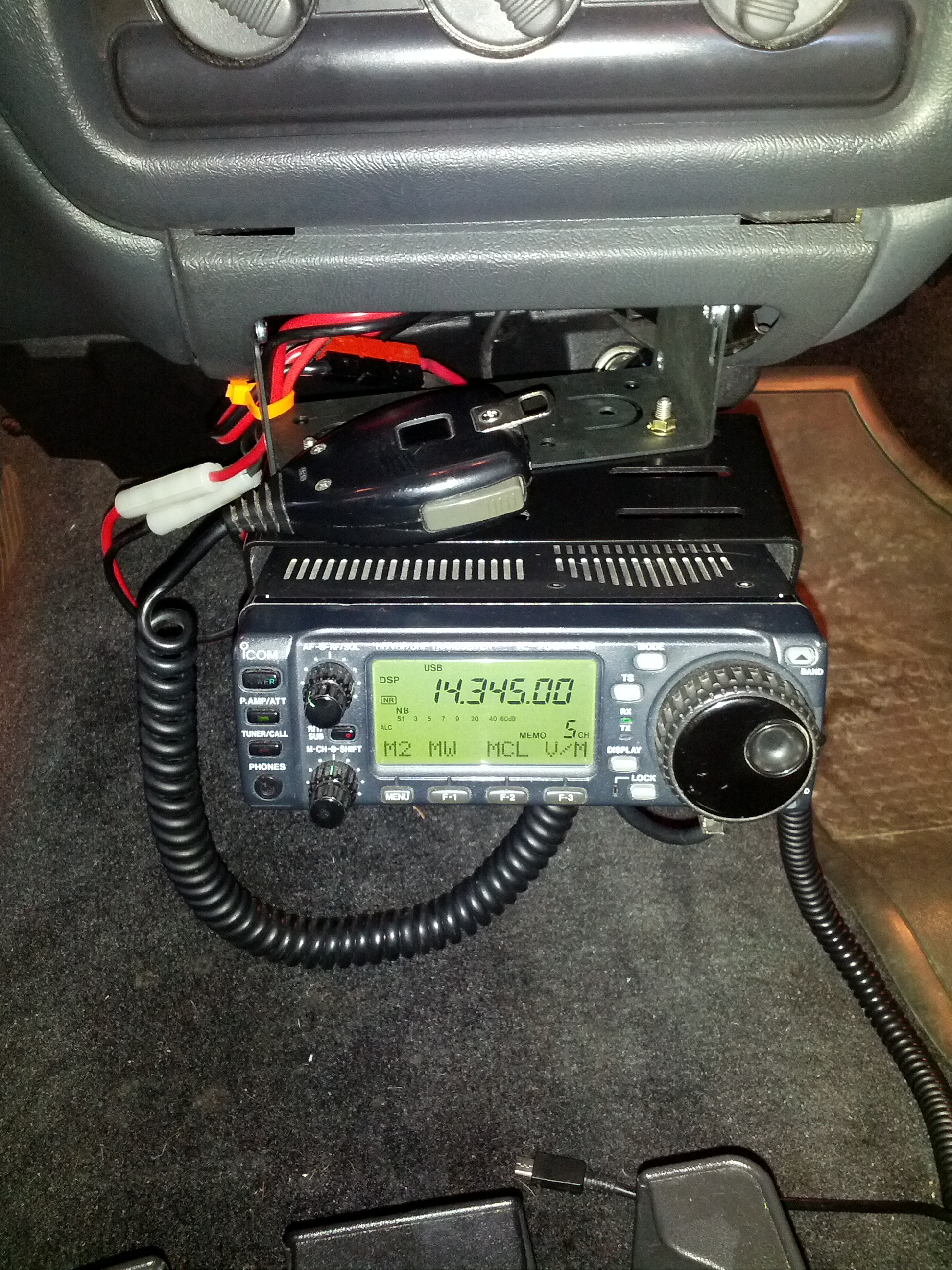
It’s in and that’s that!
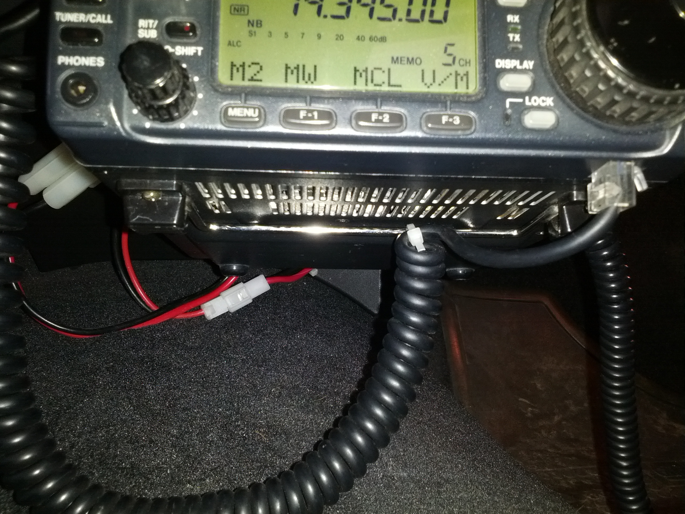
I zip-tied the mic cable to the foot on the bottom of the rig to keep from pulling too hard on the cable and damaging it. The modular cable ends are a pain to replace because the mic wire bundle is not really made for those (unlike network cable which is simple to terminate).
I also zip-tied my cellphone charger to the mount to keep the plug from pulling out (which I wouldn’t be able to fix while driving, obviously).
With all that said and done, all that remains is dealing with the antenna side of the equation, and removing the one below, which certainly feels like a dummy load… on a stick.
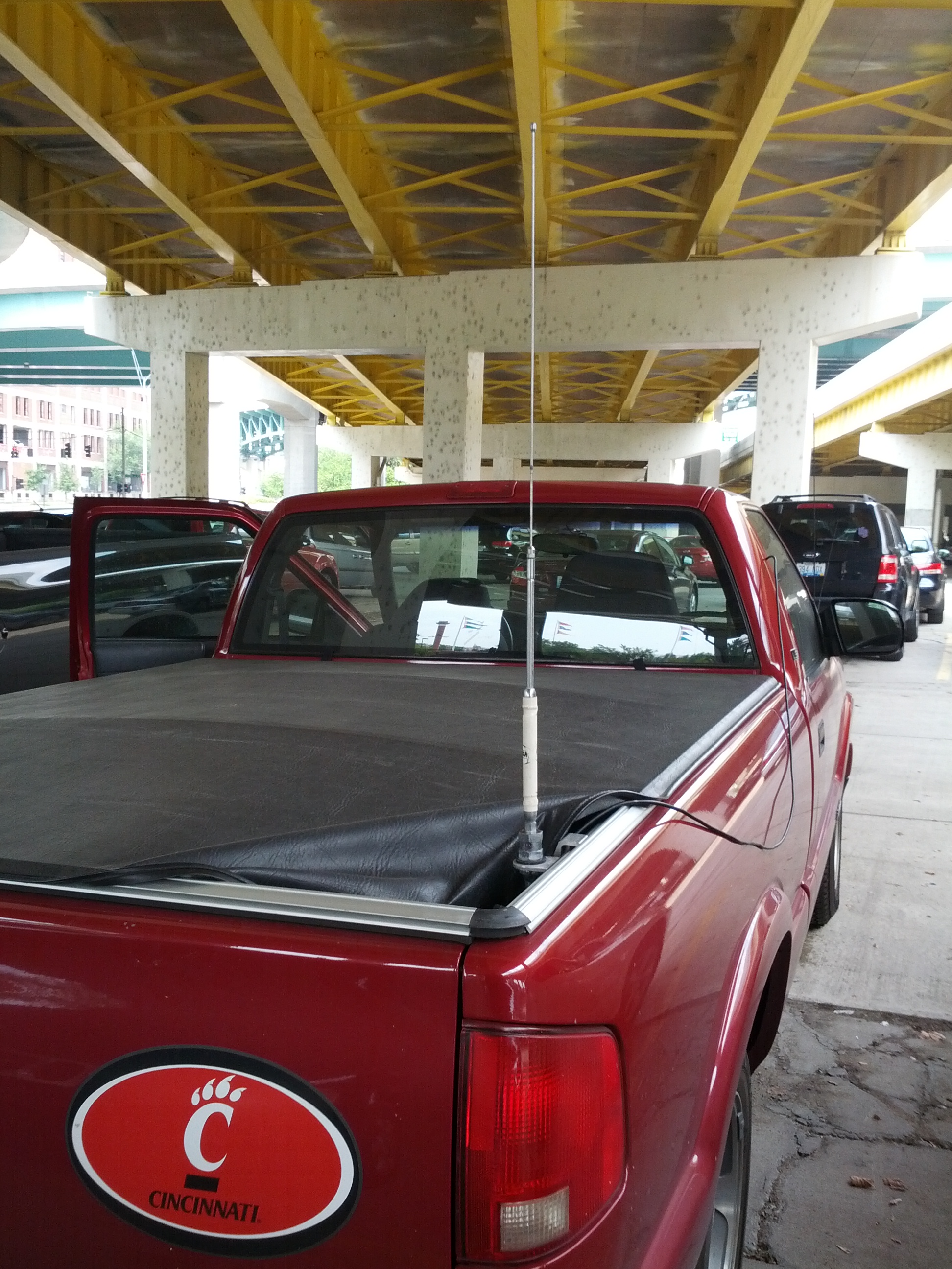
Someone gave this to me. I’m considering giving it back once I have a better alternative.
I decided to move all my radio stuff from my desktop to my laptop for now. My desktop has never been a reliable computer – there’s something wrong with it that causes it to stall (and whatever it is, it’s hardware and not OS, as it has done the same with XP or Mint). It also goes SLOOOOOOOOOOOW. In fact, it goes so slow, I tend to boot it at least 10 minutes before I need it, and it was degrading to the point where it wasn’t even ready then.
So, one thing I ~need~ want to be able to do is digital modes like RTTY (I know many hate it, but I do enjoy RTTY contests). The problem I ran into is not a new one: there’s no serial port on my laptop, meaning my old way of triggering my radio’s PTT is now a useless group of components.
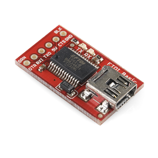
I happen to have a Sparkfun FTDI Breakout board sitting nearby. It has a damaged trace to the 5V output caused by the fact that my soldering iron is an old Radio Shack 45W pencil (which puts out far too much heat for many boards). I had set it aside with the intent to use a wire jumper to fix the problem, but after getting it back off the electronic triage shelf I realized that everything worked except the 5V output. The module looks like this (picture credit from Sparkfun):
I first wired it in with my transistor switch to look something like this:
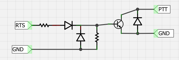
It didn’t work.
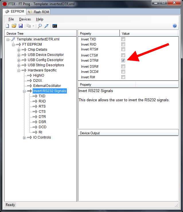
I started to investigate. I noticed that DTR, RX1, TXO, and CTS were all 5V, but DTR would drop to 0V when the DTR was activated via software.
So I did a little research. FTDI makes their boards customizable, so I looked into the software from FTDI’s website and found a configuration utility called FT_PROG. From this utility, I was able to read the chip and then re-write the chip to invert the DTR signal. Note the screenshot below:
This allows me to use the FTDI board with an optoisolator and trigger the PTT. The schematic is below:
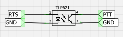
So now I just have to fix the USB soundcard issue…
-73-
Since I had a few minutes after the XYL went to bad (after a *very* busy Saturday for both of us), I went into the basement and played with the antenna analyzer.
This isn’t the most ground-breaking post on my blog, but they don’t really teach much about antenna analysis in traffic engineering classes!
Scop’d
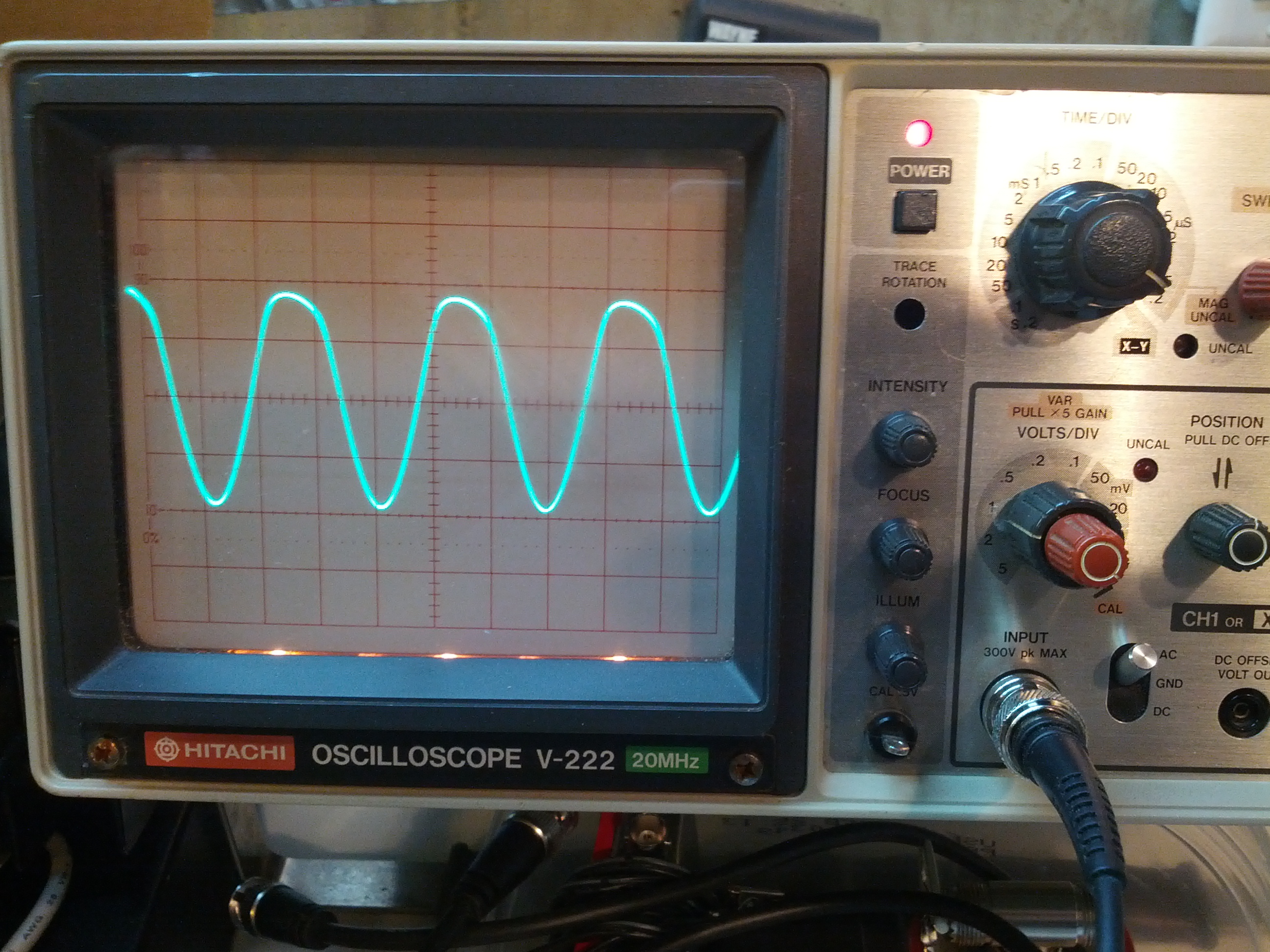
The first thing I did was drop the frequency of the analyzer to something low and see how much power the analyzer puts out. 4V peak-peak.
SWR Check – 25 Ohms
SWR is based on the mismatch between the impedance of the source and the load. So a 2:1 SWR could mean that the load is twice or half the source impedance. So I decided to put a few resistor arrangements on the analyzer and see if what happens is what I thought would happen.
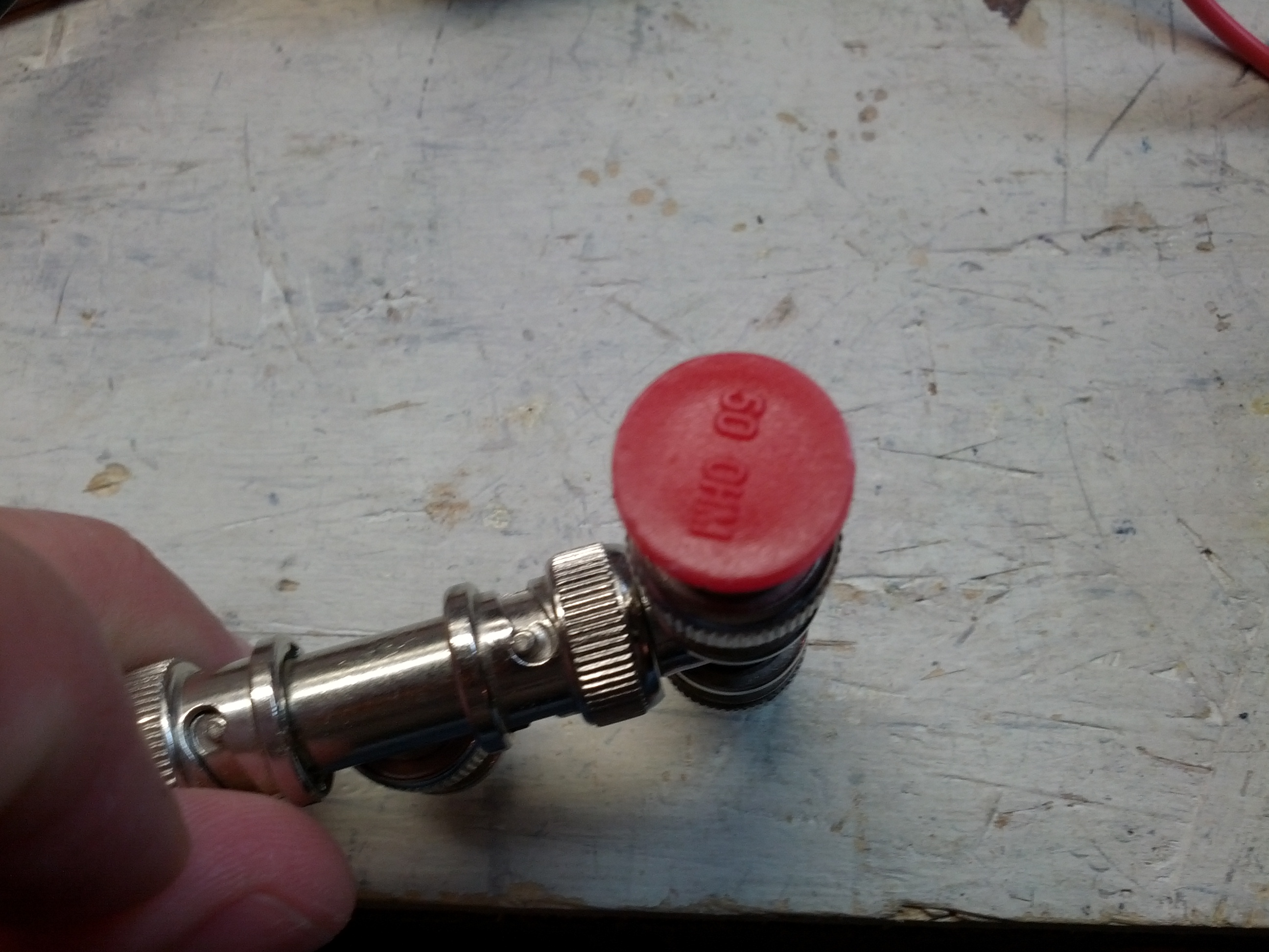
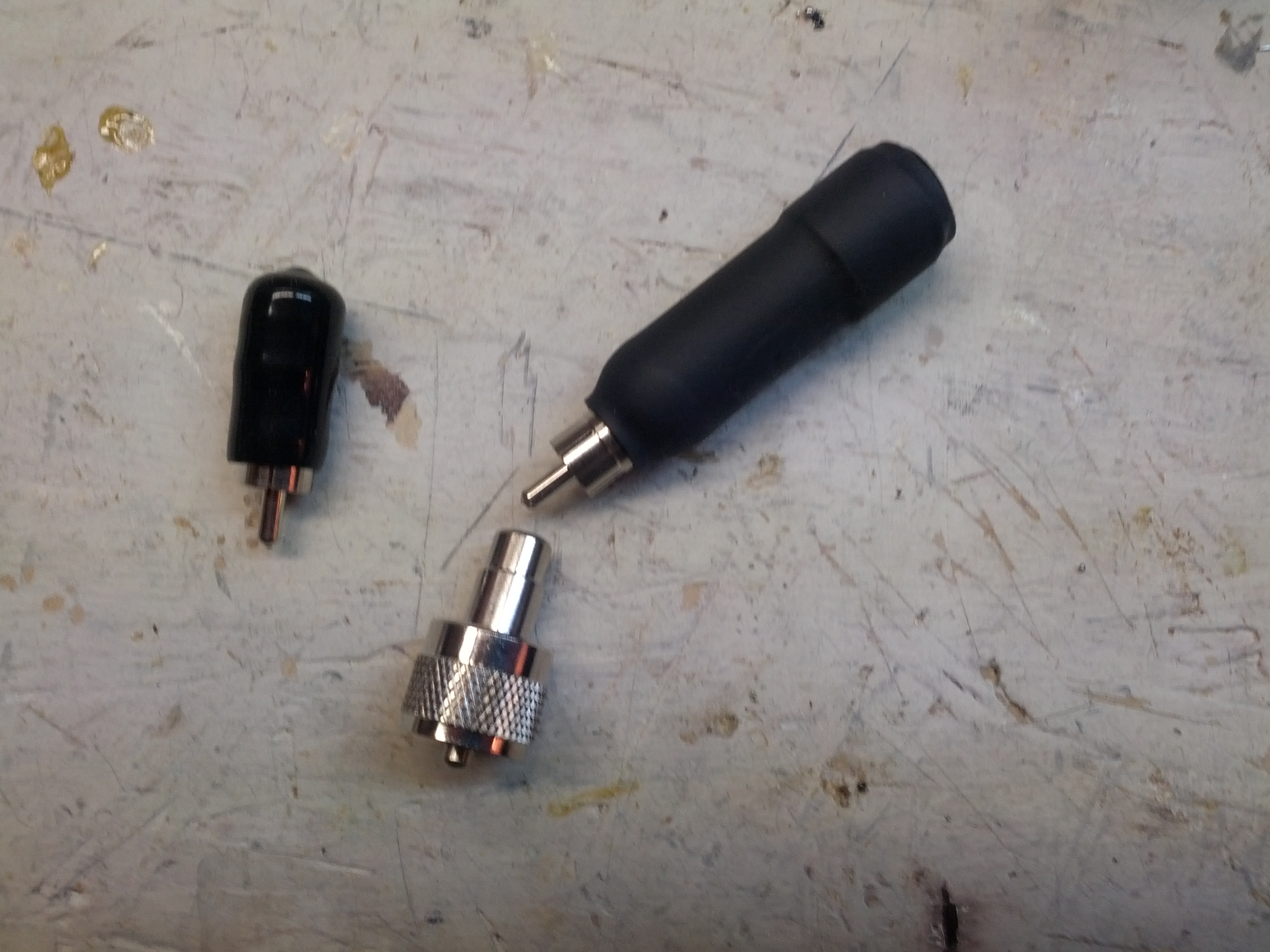
So I had these terminators from way back when they used BNC token ring networks. I’ve never worked with anything but Ethernet (using RJ-45 connectors), so I’m not sure how I got these, but they came in handy for this.
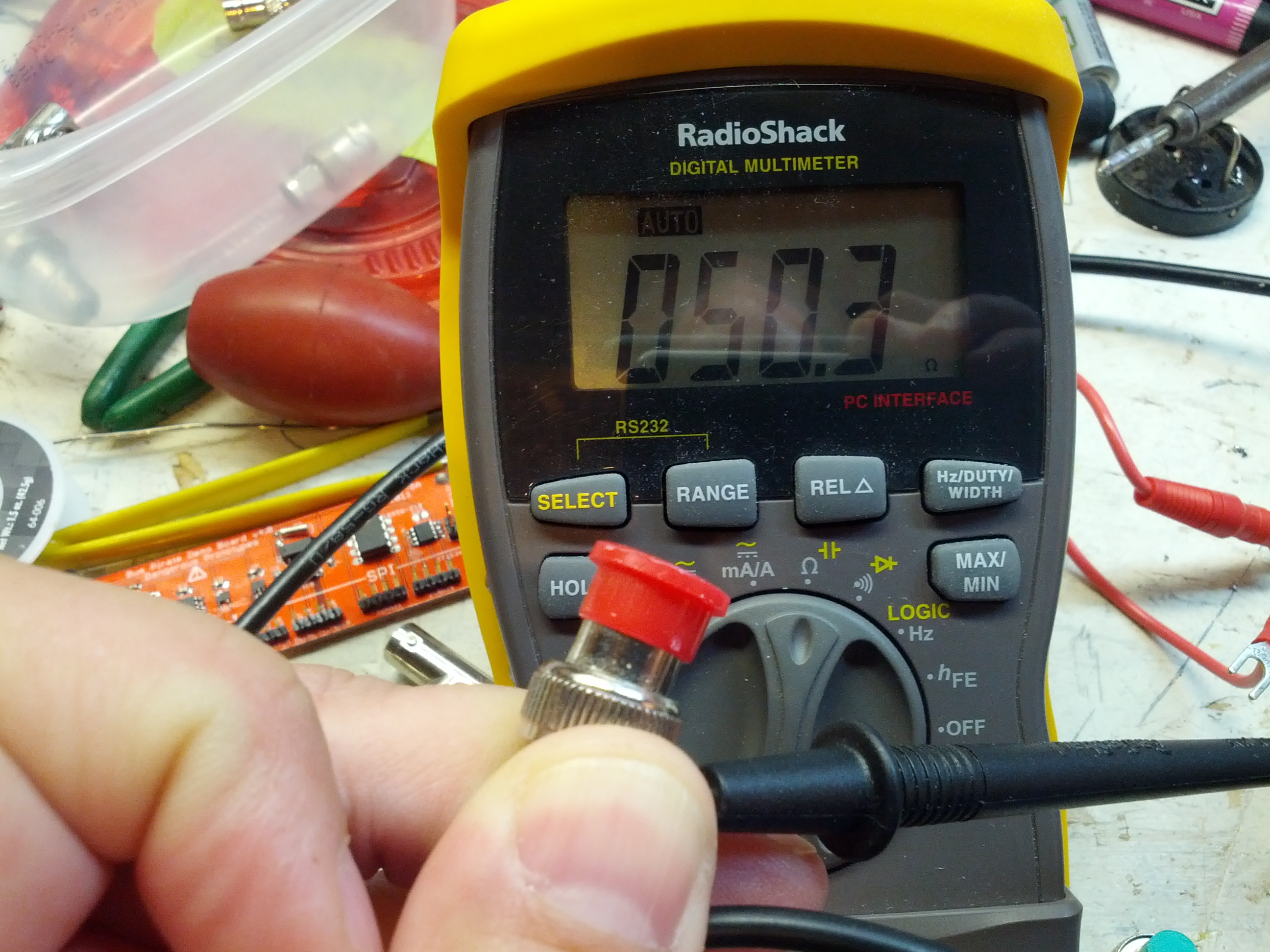
This one is 50.3 ohms. Within a 1% tolerance.
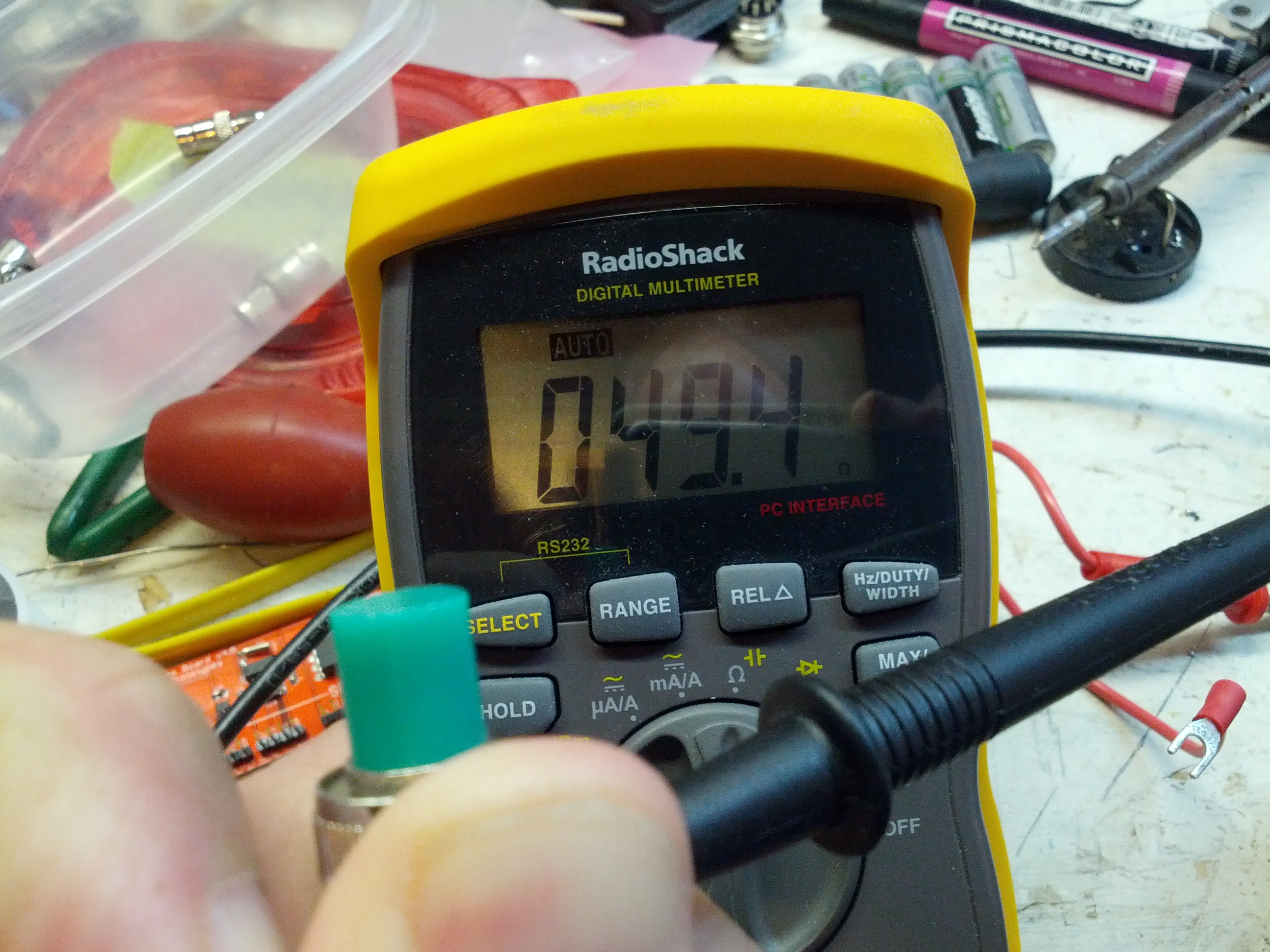
This other one is 49.4 ohms. Just around 1% off. For what I’m doing, close enough.
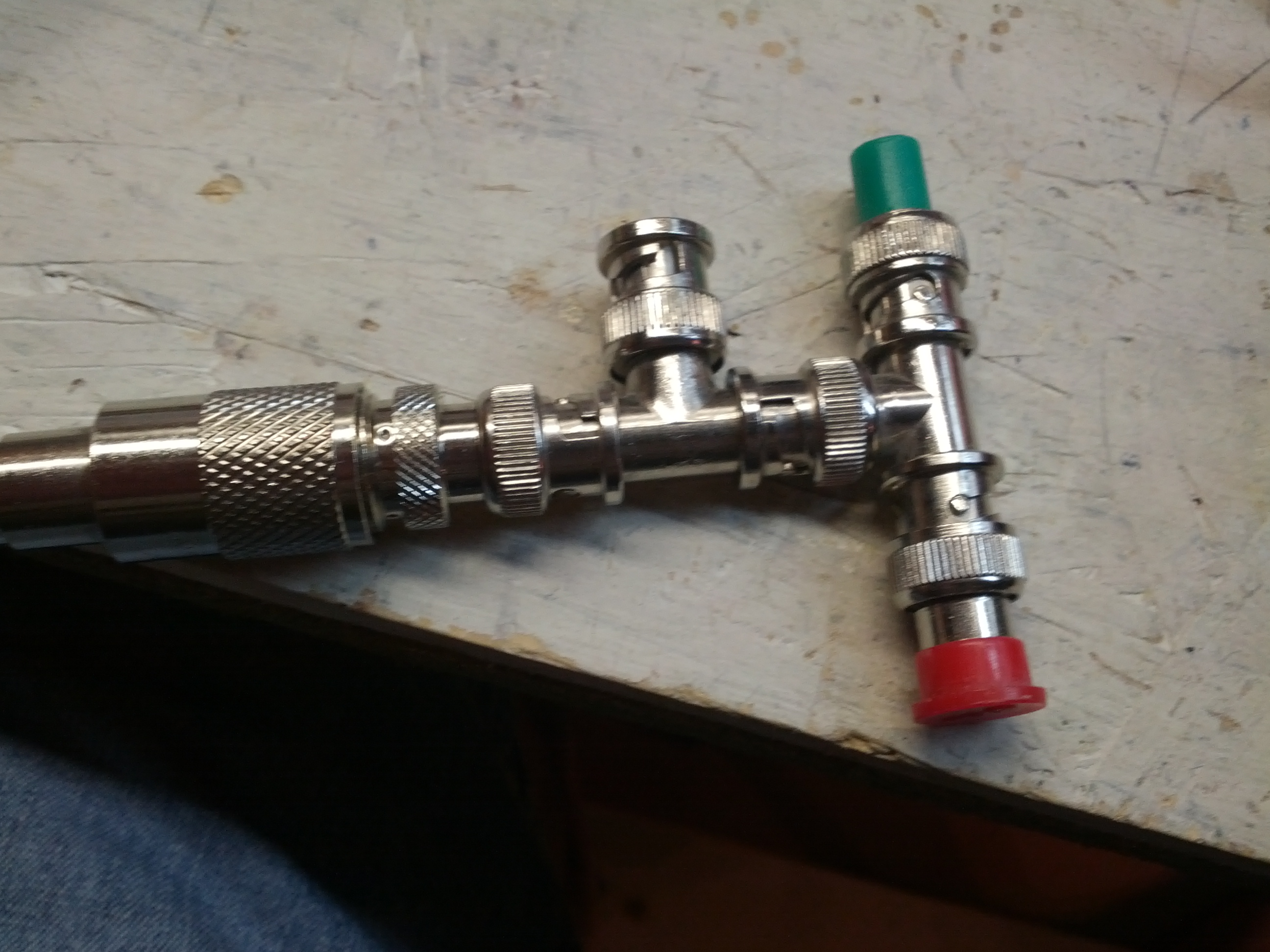
This was my redneck arrangement. This basically put the two 50 ohm terminator resistors in parallel.
This doesn’t quite have the resistance I was expecting, but the SWR is correct. Of course, there’s all sorts of stuff going on with the open end, the many connectors, and the 4 foot piece of RG-58. Given the fact that I had two 50 ohm resistors in parallel, I think I should be seeing 25 ohms R and (ideally) 0 ohms X.
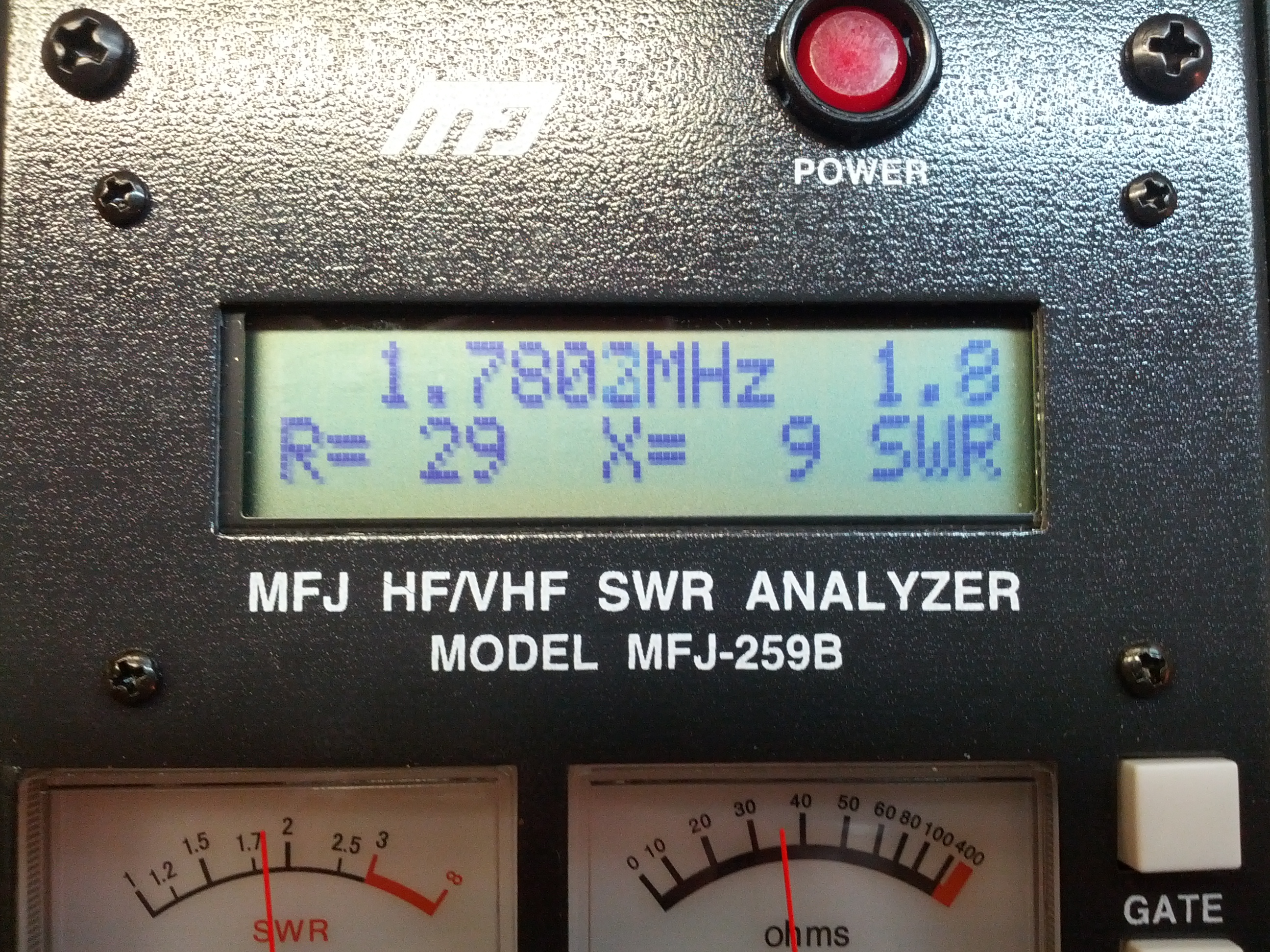
This seems a little more like it. Still a nearly 2:1 SWR and close to 25 ohms R, with very little reactive ohms.
SWR Check – 100 Ohms
Since I couldn’t figure out a way to make my two BNC terminators in series, I pulled a resistor out of my parts bin. It was really a 98.3 ohm resistor, according to my non-lab-grade Radio Shack meter, so I figure that’s close enough!
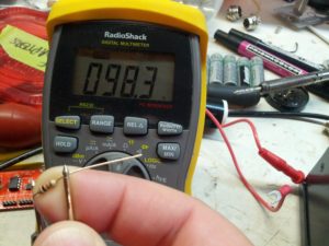
Close enough to 100 ohms.

This is how I did it.
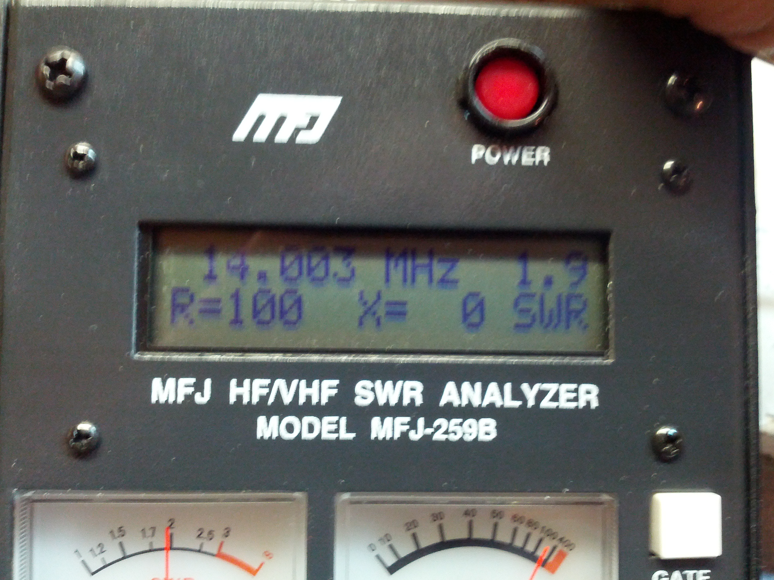
Hey look, exactly as expected. 100 ohms resistive, and 0 ohms reactive.
Other Dummy Load Test
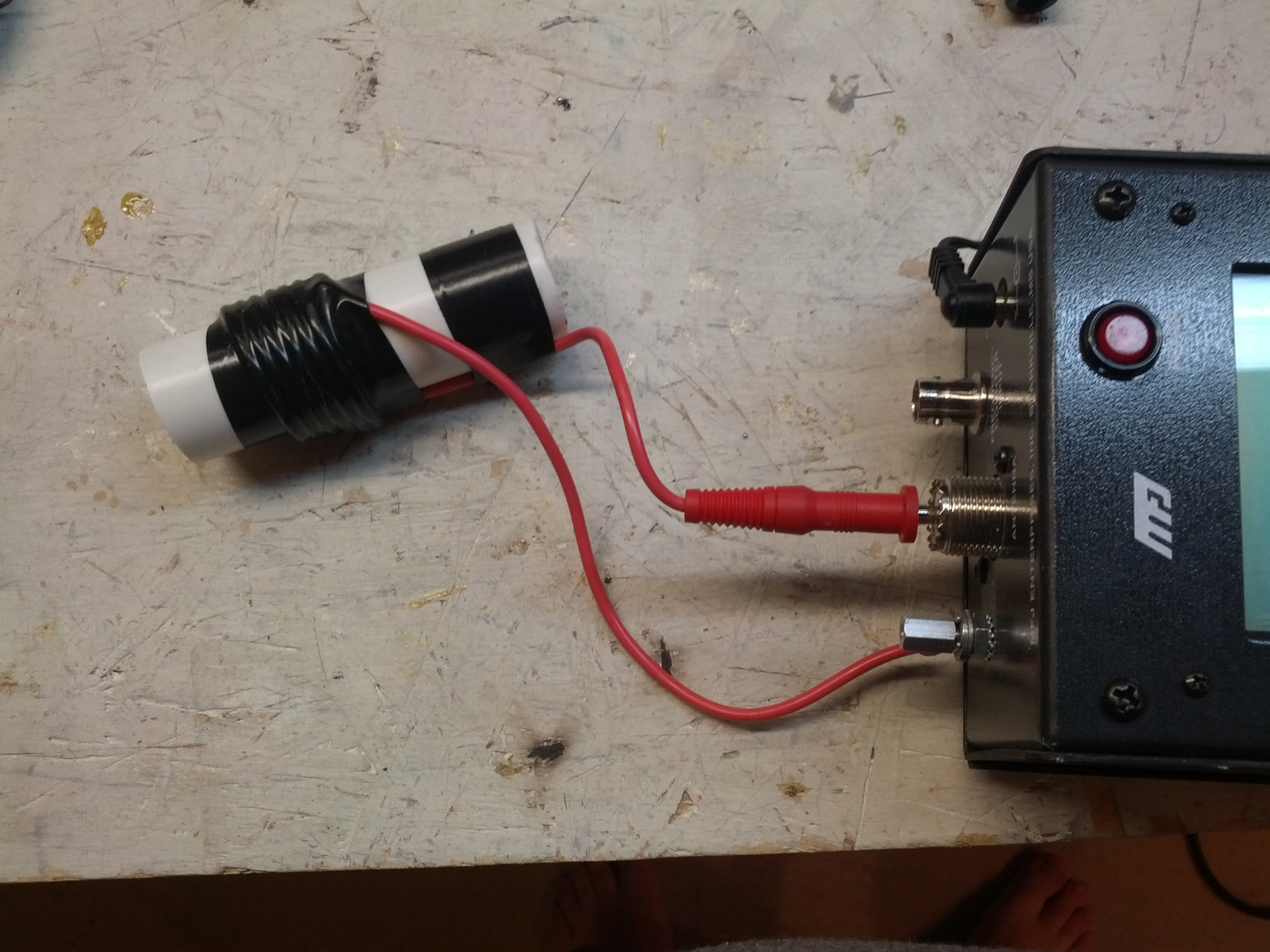
I had a dummy load I built for QRP uses (specifically the Softrock). I built it a while back, which is why the callsign is wrong.
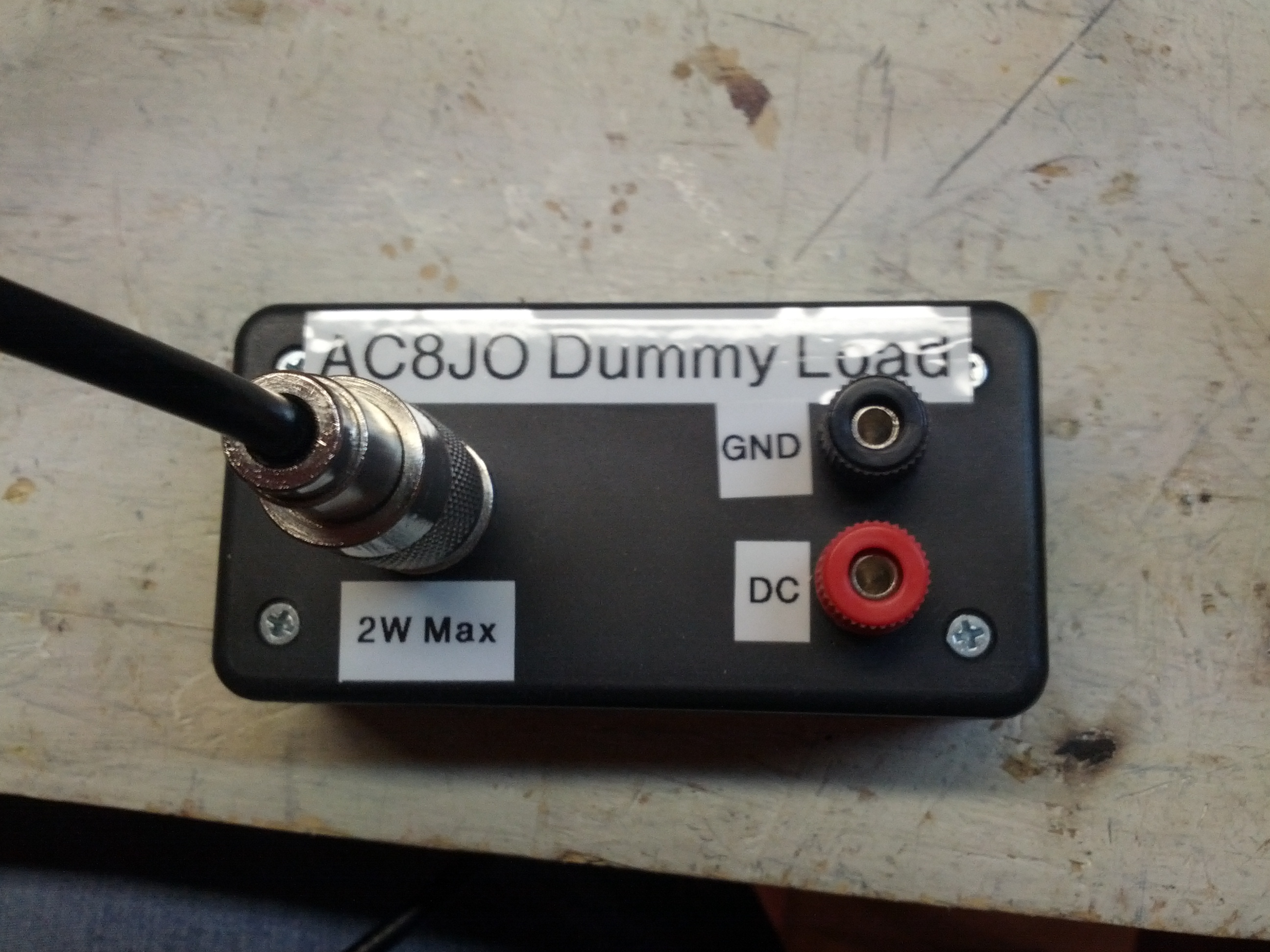
Just pretend it says “KE8P Dummy Load” 🙂

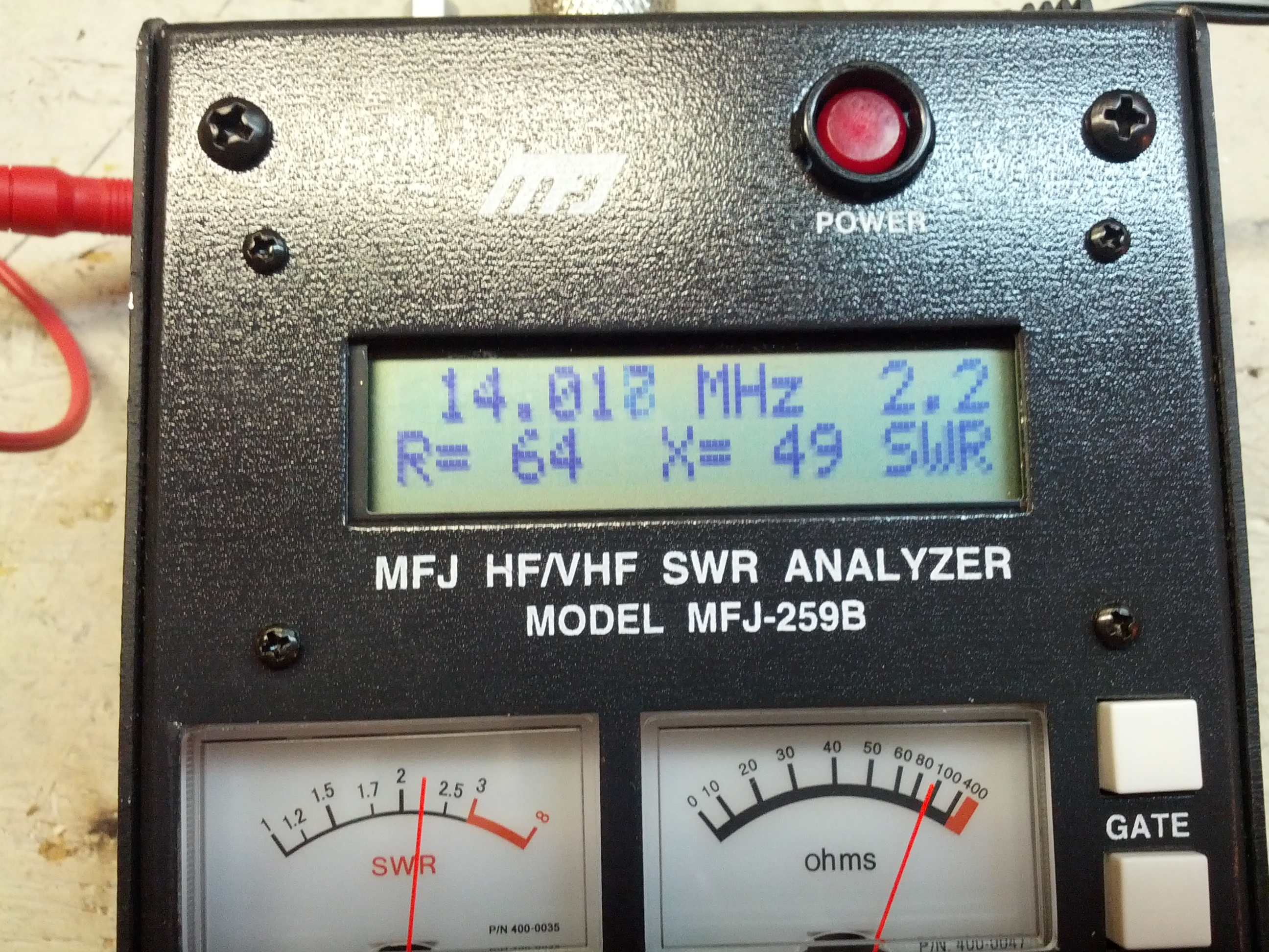
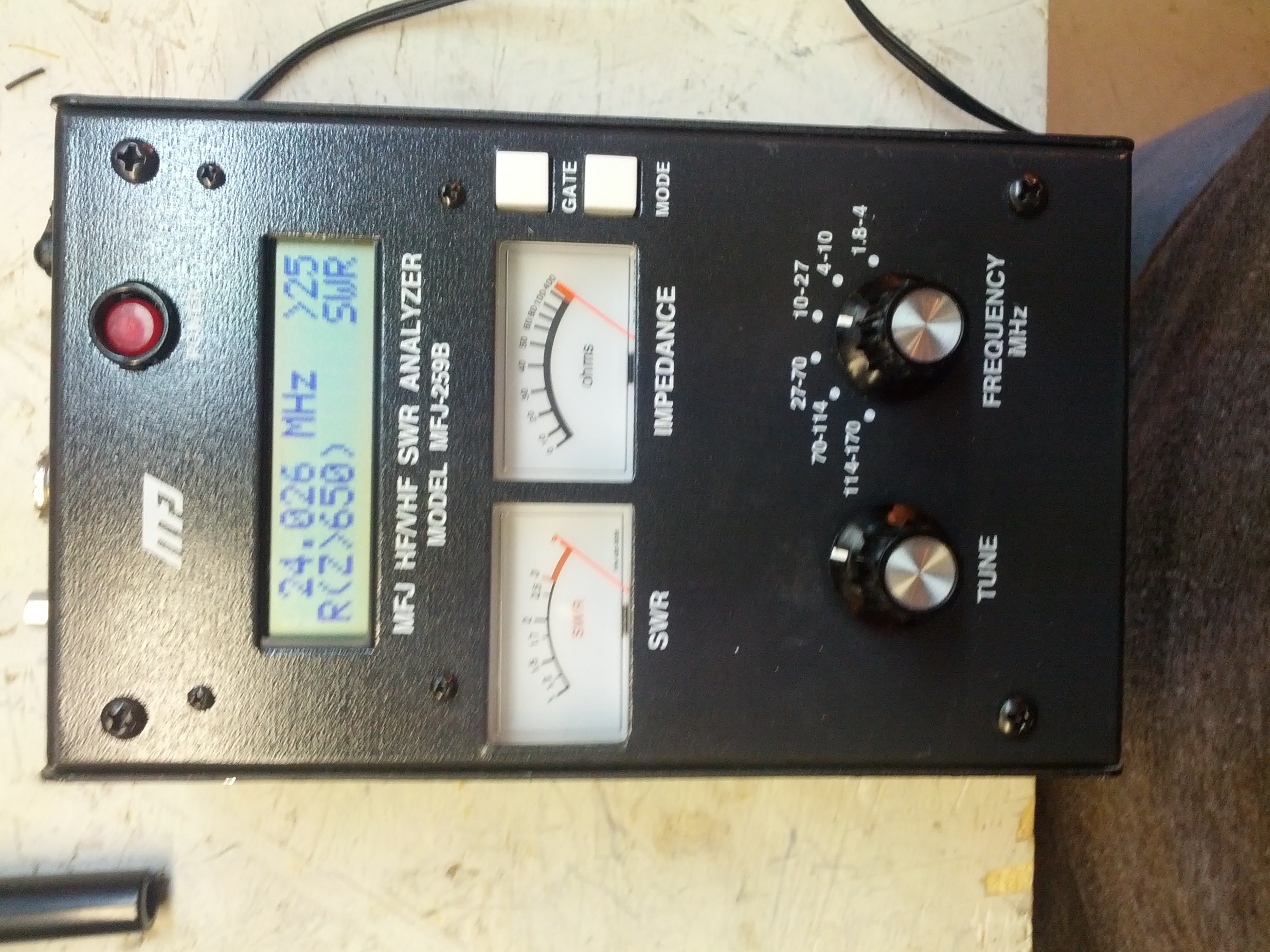
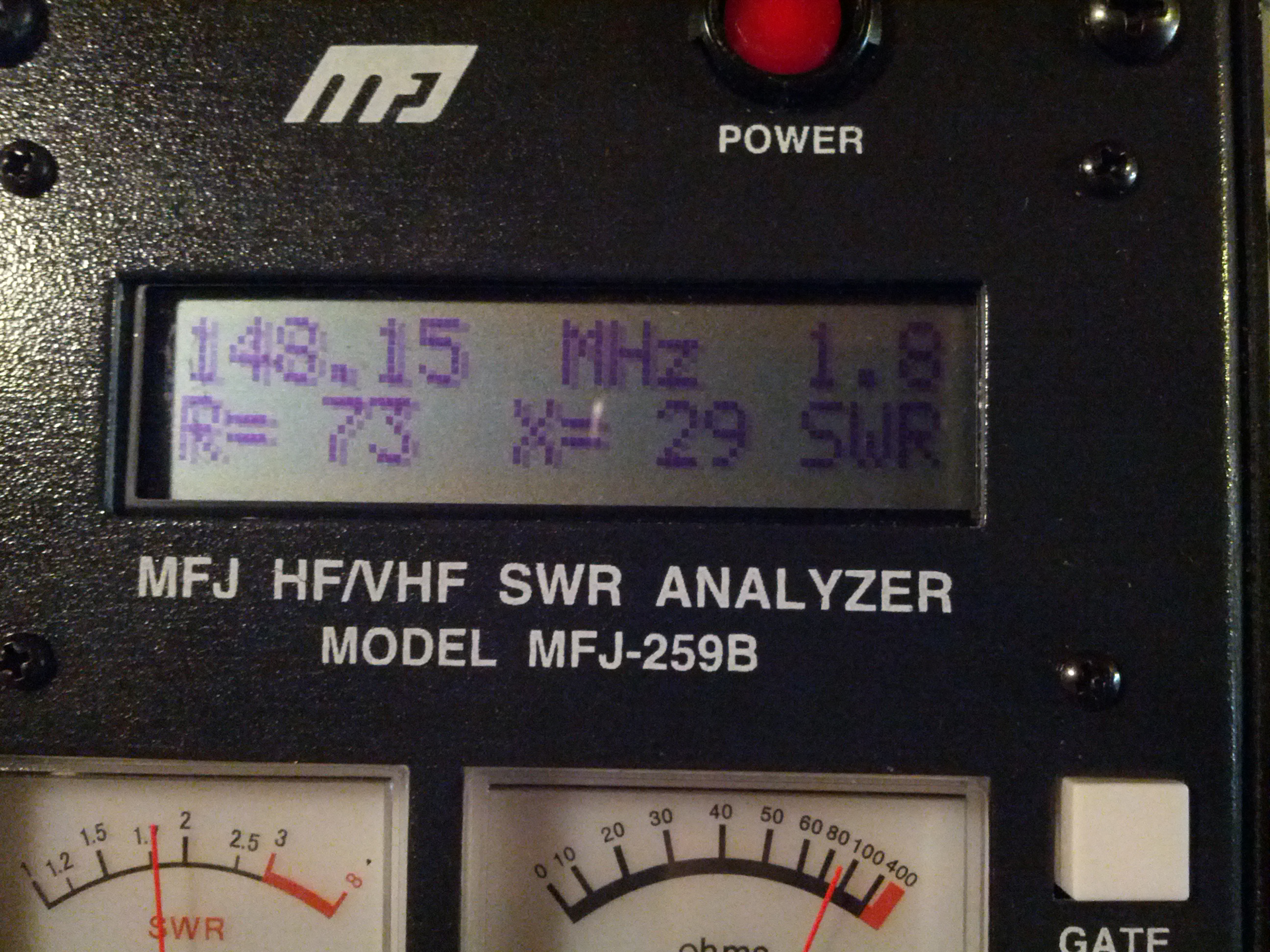
70 and 4? SEVENTY AND FOUR? WTF, it should be 50 and 0!!! I’ll just blame the extra resistance and all the reactance on the cable…
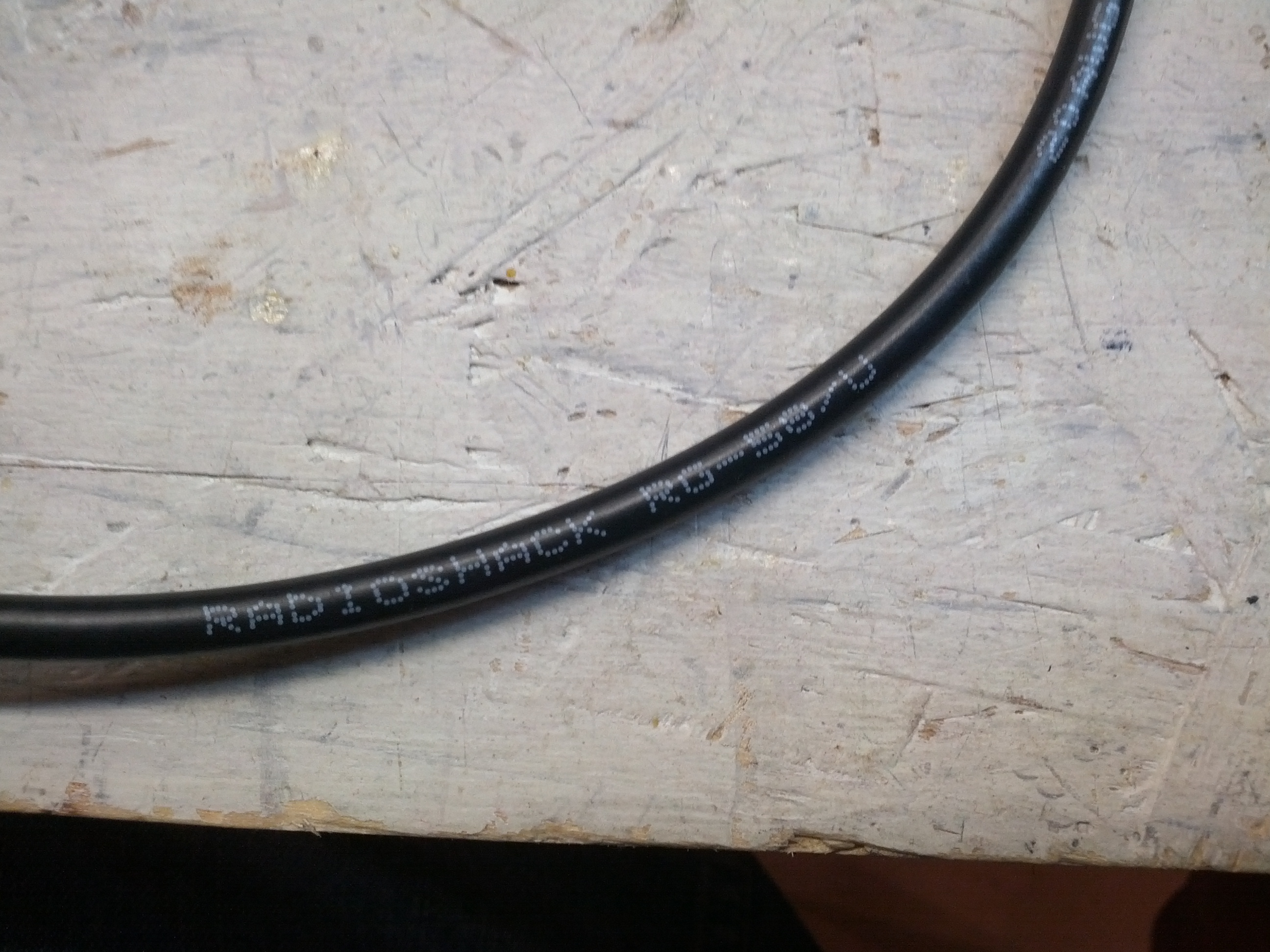
Maybe this is why it isn’t perfect. My coax isn’t exactly Belden or Times.
Capacitance Checks
So the MFJ-259B has a capacitance check on it. This is really for the capacitance of an antenna, not for what I did in the pictures below. I basically took a ceramic disk capacitor and clipped one end to the ground and the other I held into the center conductor of the antenna port. This is a 10,000 pF capacitor.
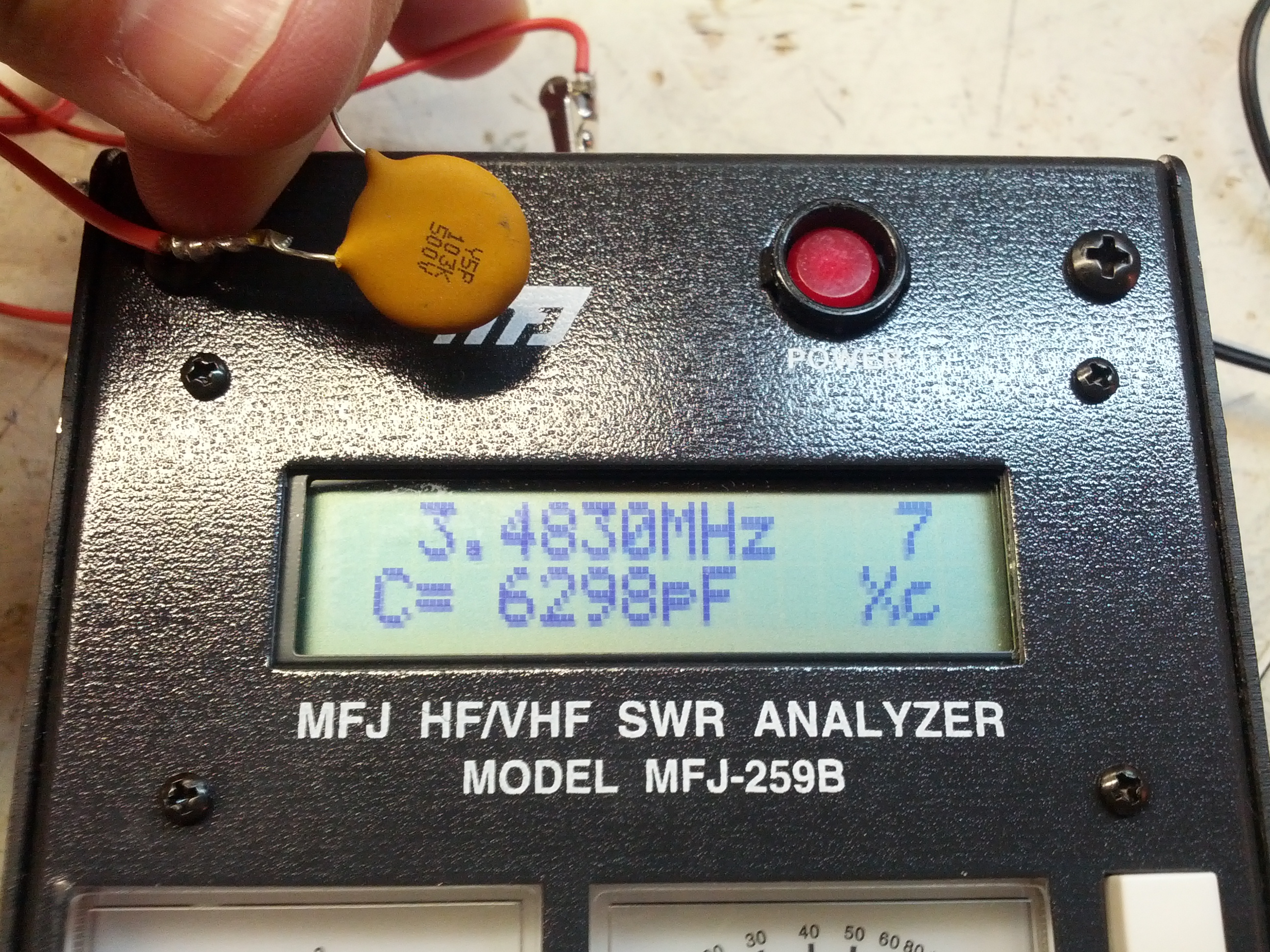
On 80m, this capacitor has 6,298 pf.
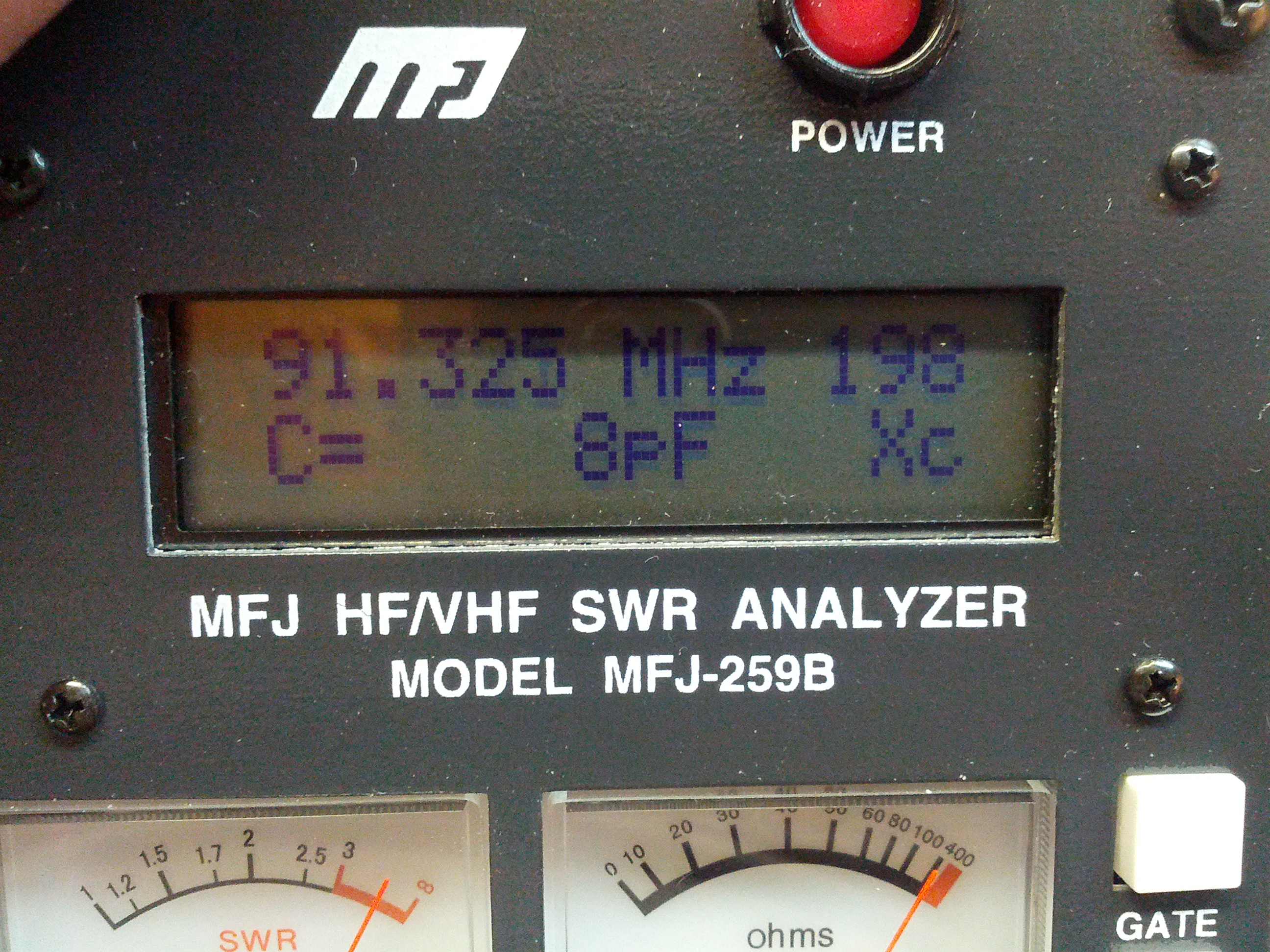
Up at 91 MHz, there’s only 8 pF of capacitance.
I figured the stuff above was a little more fun than me talking about how I tested every antenna I own… again.
-73-
Oh crap, that probably sounds bad. Ah well.
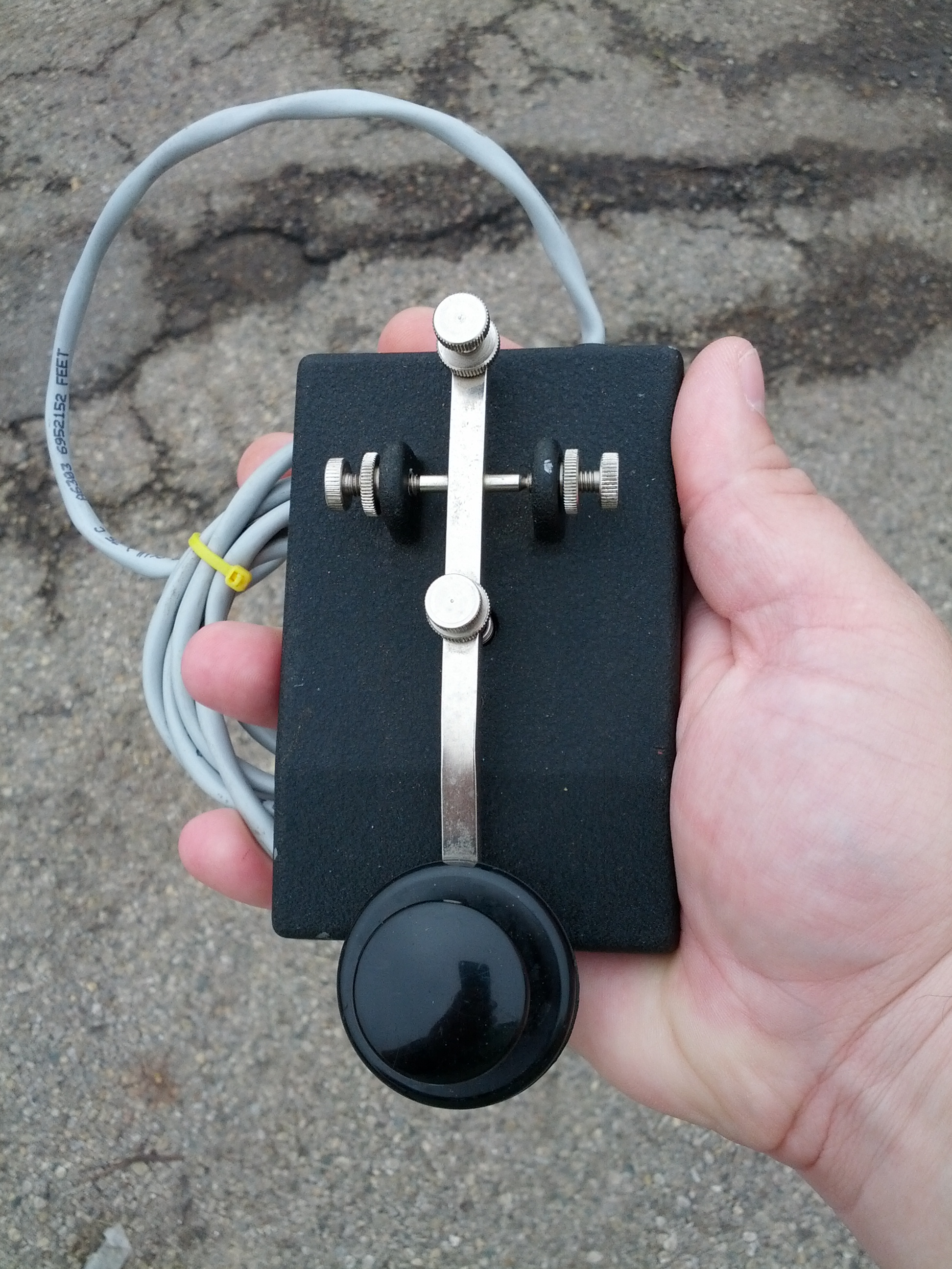
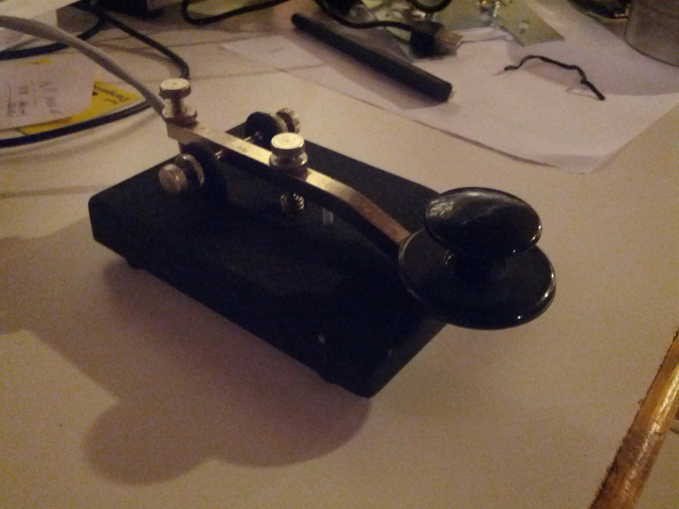
So my first find was a key. It’s nice, heavy, and probably has a history, which I added “purchased for $35 by KE8P” to.
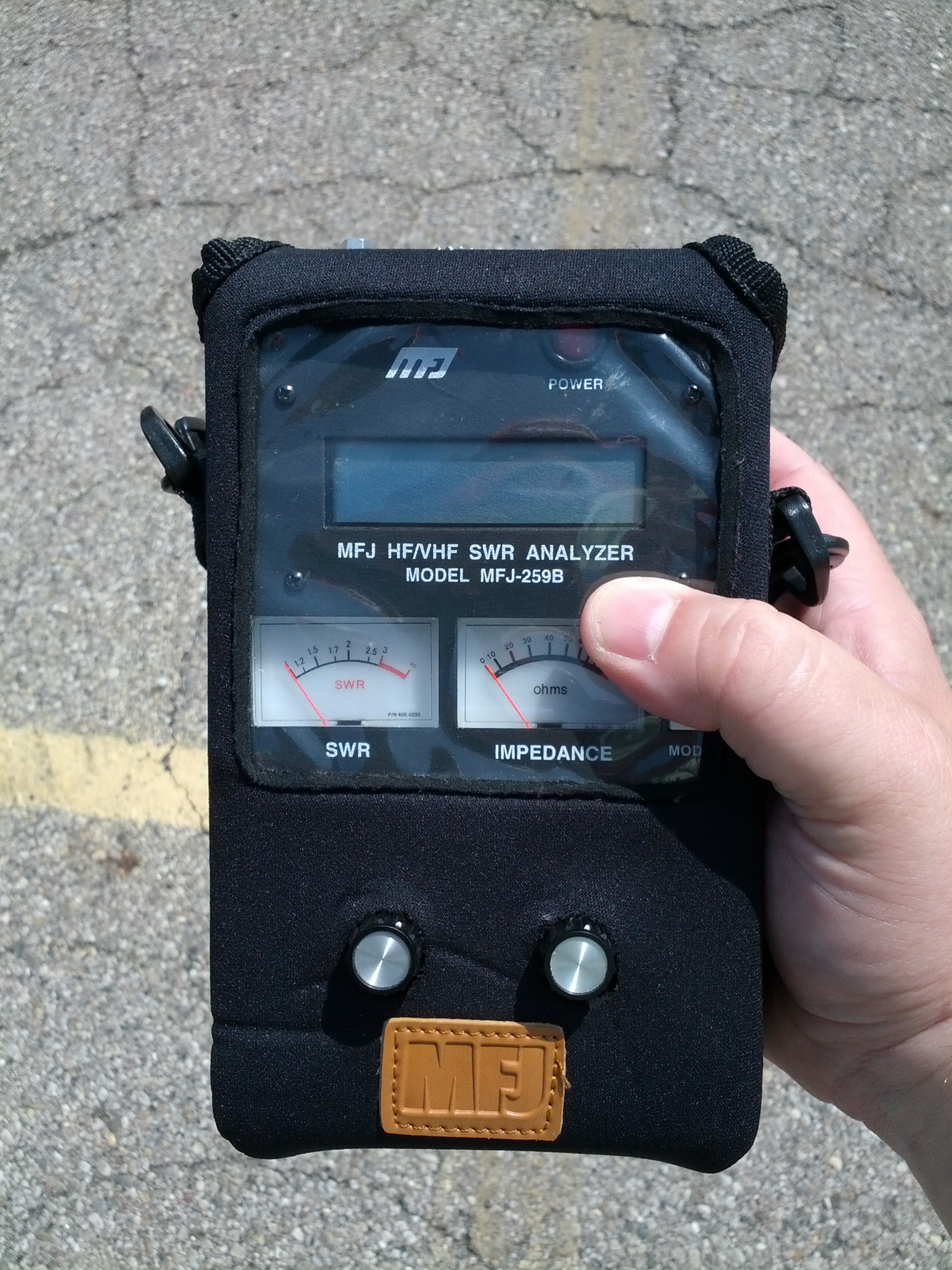
I found this. For $165. Like any normal ham that likes to push buttons and turn knobs, I turned it on, just to be greeted with it flashing “LOW VOLTAGE 6.5V”. I figured that was a sign that it probably works.
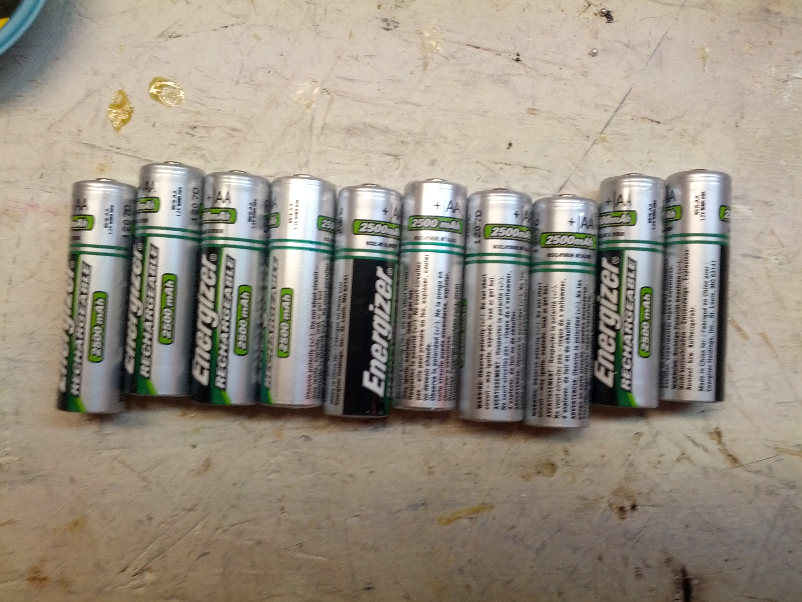
And when I got it home, I found these in it. Ten Energizer rechargeable batteries.
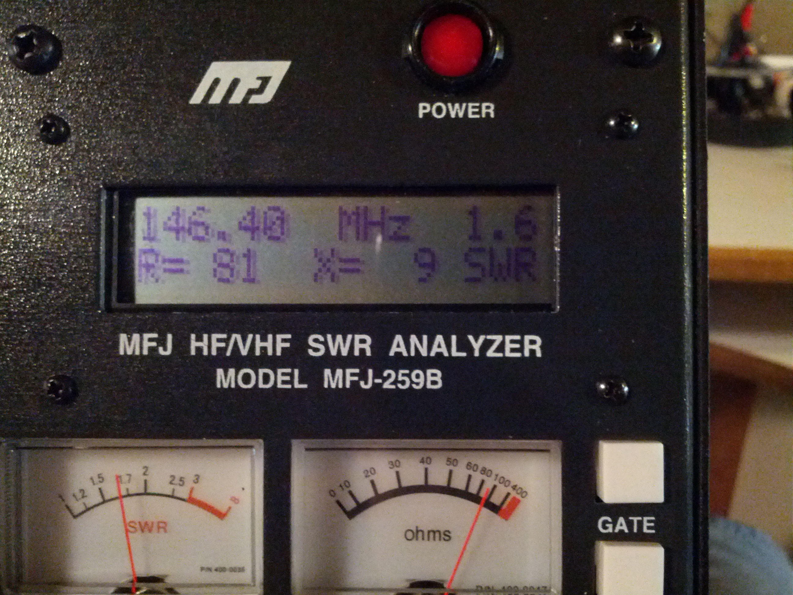
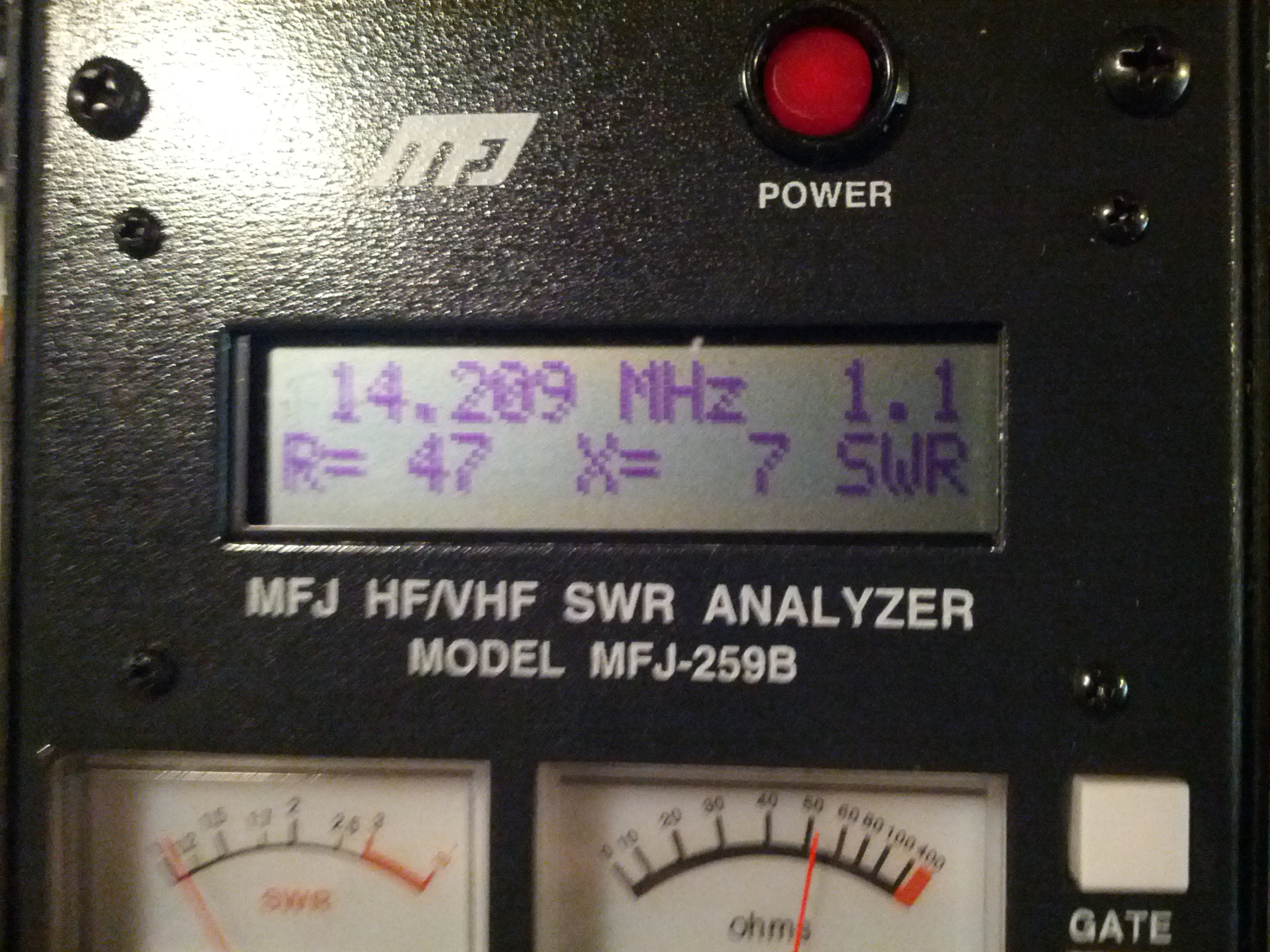
So I removed the batteries and plugged in a wall wart. I was greeted with “VOLTAGE OK 15V” and something like the display in the picture above. I did check my dummy load, it claims it is around 50 ohms at 1-1.3 SWR. Guess it works!
Also included were these. They are coils to use the analyzer as a dip meter. I didn’t really need these, as I built one (they’re really quite simple). My built version worked quite well for the coax traps on my attic trap dipole.
So I did try it with my HF and 2m antennas…
Not bad for the severe destruction of 5 clothes hangars
My HF antenna isn’t too bad on 2m…
…and it does okay on 20 meters, too…
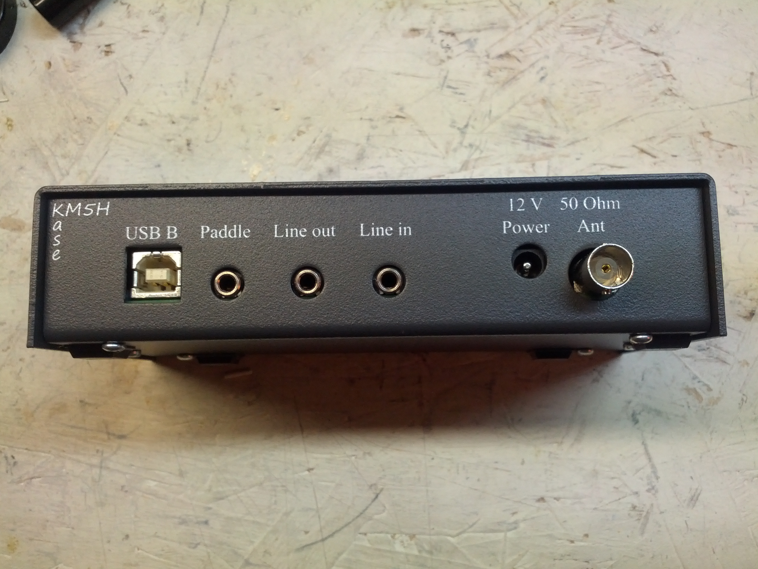
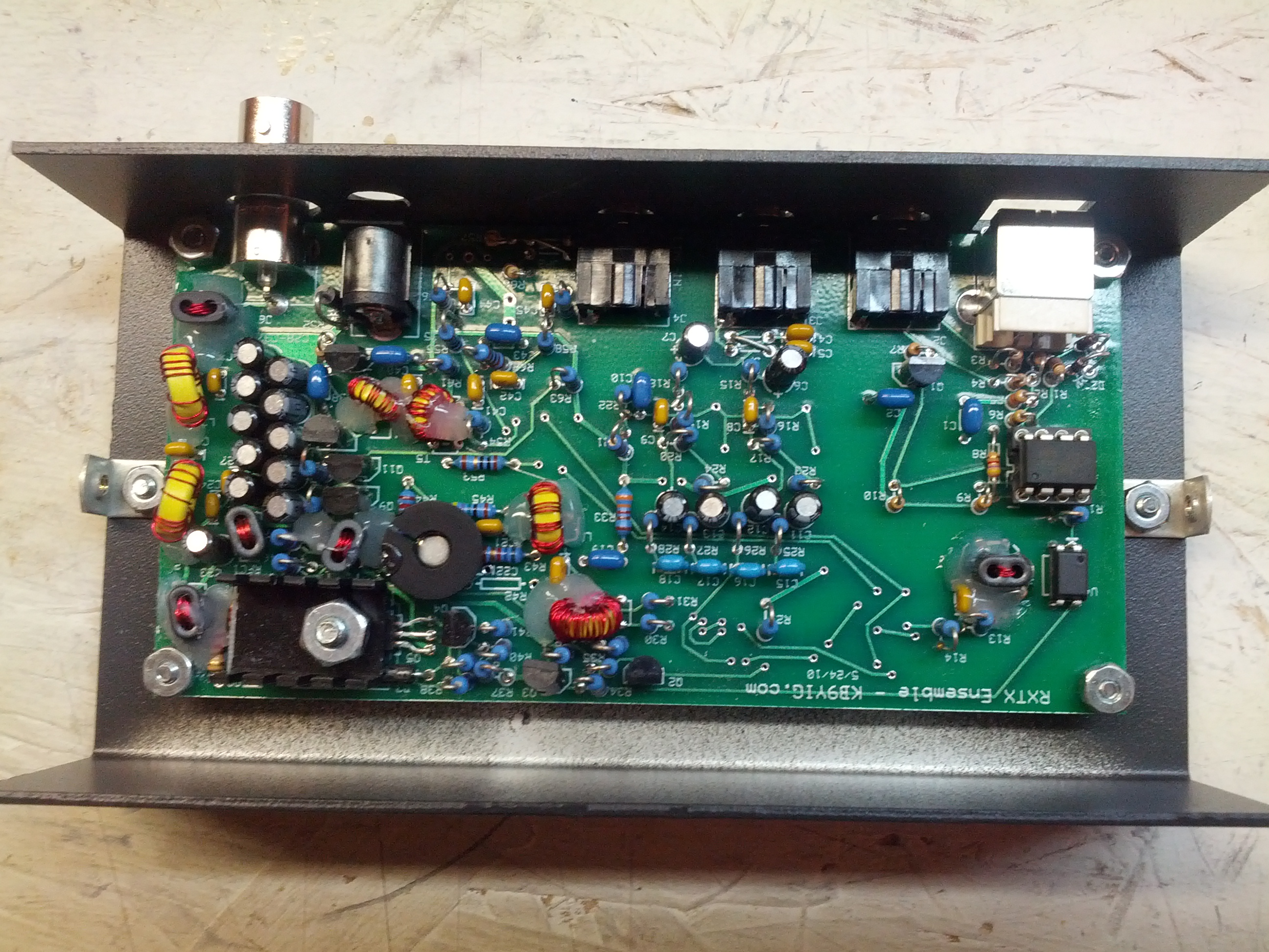
The third purchase was a case for my SoftRock
The last thing I got was some fiberglass mast. I didn’t take a picture of that.
This year is different from any of the past two years I’ve gone to Dayton. The first year I went to Dayton, I wanted a simple HF rig and knew my budget only supported something like a Radio Shack HTX-100. I bought two for $45. I also bought a power supply for it (an Astron RS-12).
Last year, I was looking for an LDG tuner for my IC-706. Found one for $85. I’m not even sure I bought anything else.
This year, my tastes are hopefully smaller.
- A nice straight key… for a damn good price
- The ARRL CW book that just came out… if it is a damn good price
- Some air variable caps… I could use some smaller ones as well as some matching pairs for matching antennas
- Maybe some tubes (for both a linear and potentially for a guitar amp for my brother-in-law)
- Probably some other parts
Dayton’s Friday through Sunday, and this blog post wouldn’t be complete without a list of what will be in my bag.
- An umbrella (maybe my raincoat)
- A small notepad and pen
- A small bag of snacks (last year, it was goldfish crackers)
- My HT and headset
- A backup battery for my phone
- A bottle of water (disposable)
- A towel (small)
Things I know I will buy:
- A beer 🙂
Things I know I will get:
- Another Dayton Pin
- A Yaesu hat (if they have them)
Things to keep in the Truck
- A bath towel… rain is expected!
- A small cooler with ice and a few bottles of water
Other Stuff
Last year, there was a guy from Linux in the Hamshack. If he’s there again, I may give them a donation since they did direct some traffic to my website (and that was totally unsolicited). I listen to their show far too seldom, and it is an interesting show.
Last year, I tried to make it a point to make it to some of the forums. This year I might, but probably not as much – I tried to attend the microcontrollers forum last year, there were no seats available in the oven… er, room… when I got there.
I have been accumulating projects on my workbench, and it is getting near time to jump into them. I thought I’d do a quick blog post discussing my immediate plans.
Antenna Analyzer
I bought a pair of direct-digital synthesizers a month or two ago, and the first thing I want to do is build an antenna analyzer, which is something I desparately need. In fact, it would be good for some of my next projects.
Balanced Line Antenna Tuner
I ran a new antenna in my attic, and wanted to be different, so I ran ladder line to it. My tuner with my IC-706 is an LDG IT-100. It is a great tuner, but it is really meant for unbalanced coax. I want a real balanced line tuner. In the meantime (and as I write this), I’m going to build a balun for it.
QRP Transmitter
Since I have two direct-digital synthesizers, I figured the other can be a part of a QRP transmitter. CW only.
APRS I-gate/Digipeater
My area is pretty bad with regards to APRS. I’m going to fix that.
Frequency Counter
The last thing I want to build is a frequency counter. This will likely be my first project with a PIC microcontroller. It won’t make it up past 150MHz, but I am going to try to hit 150 MHz.
I bought a new-to-me radio. It is a used FT-7800R dual-band (2m/70cm) mobile. The price was right: $195 before taxes. Once I got it, I high-tailed it home and opened the box and….
POW.
It hit me. The stink of cigarette smoke. Not enough to knock me over, but enough to potentially stink me out.
So I asked Twitter, Facebook, and a few locals how to get the smell out. Their answers (all good ones) are in the Storify story below.
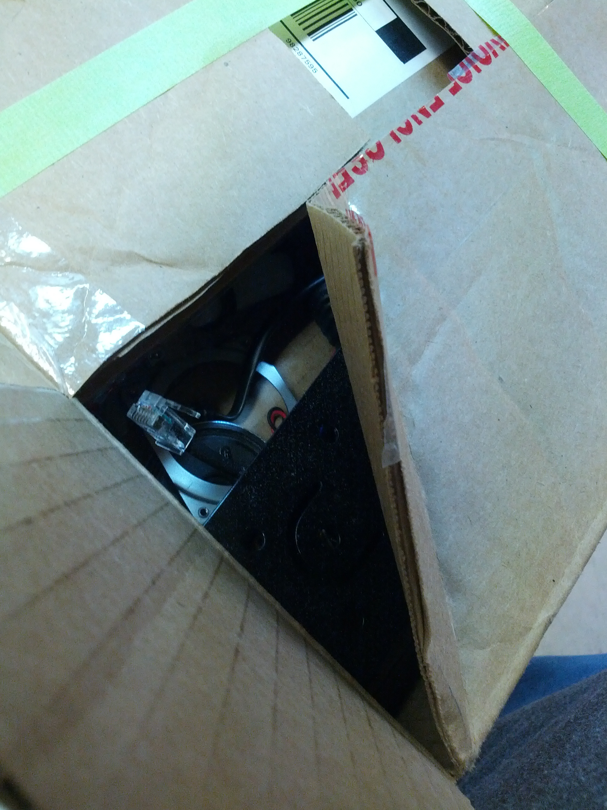
So I did with what I could with what I had. The images below tell the story.
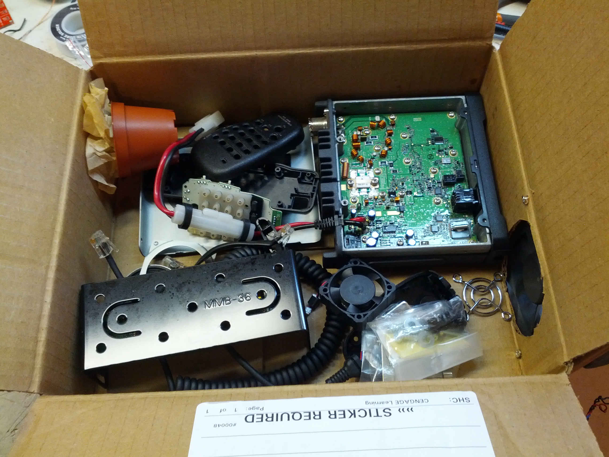
I took the rig apart and put it in a box.
I sprinkled lots of baking soda all over the parts. I left it like this overnight.
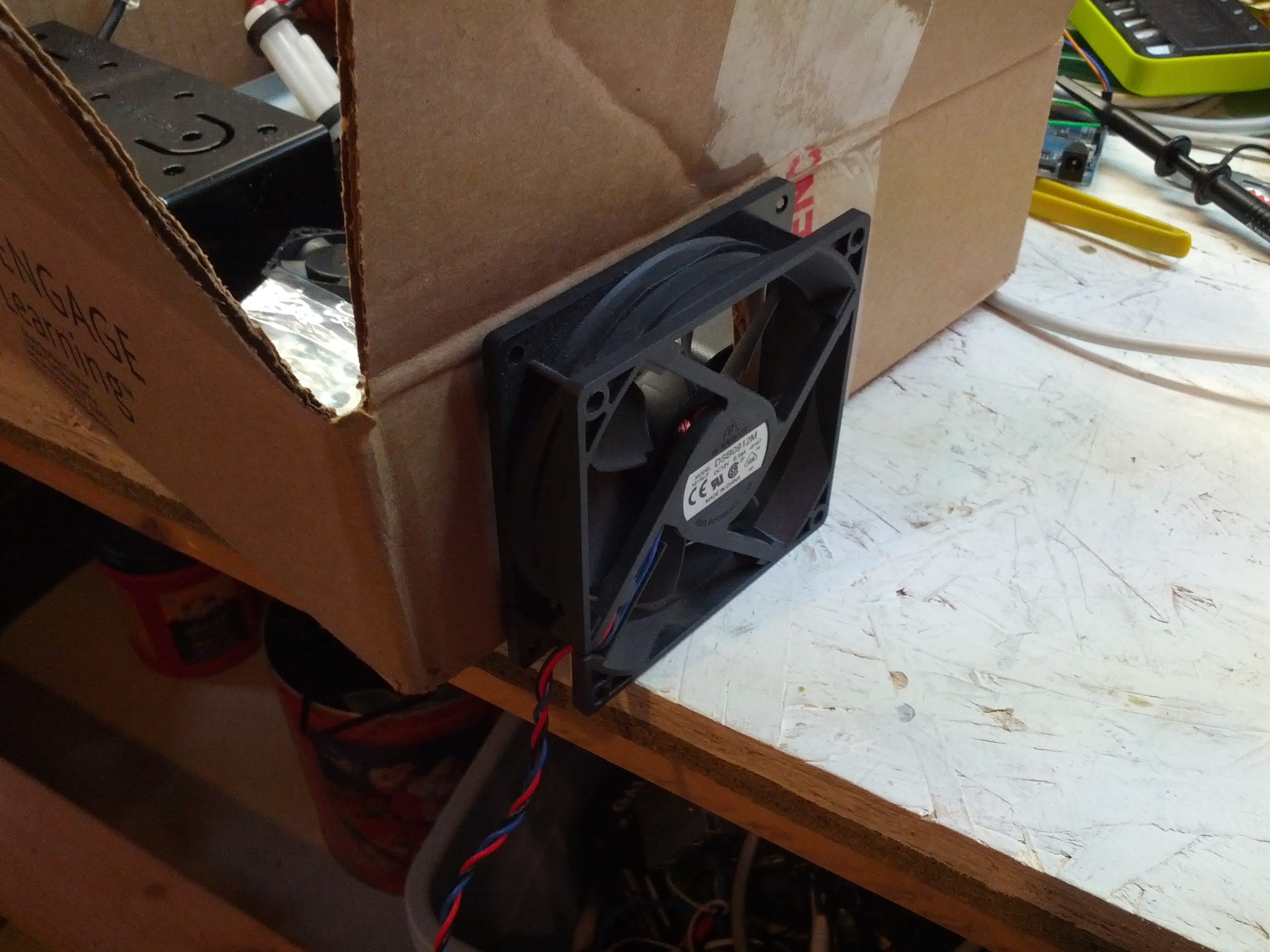
I attached a fan to the side of the box.
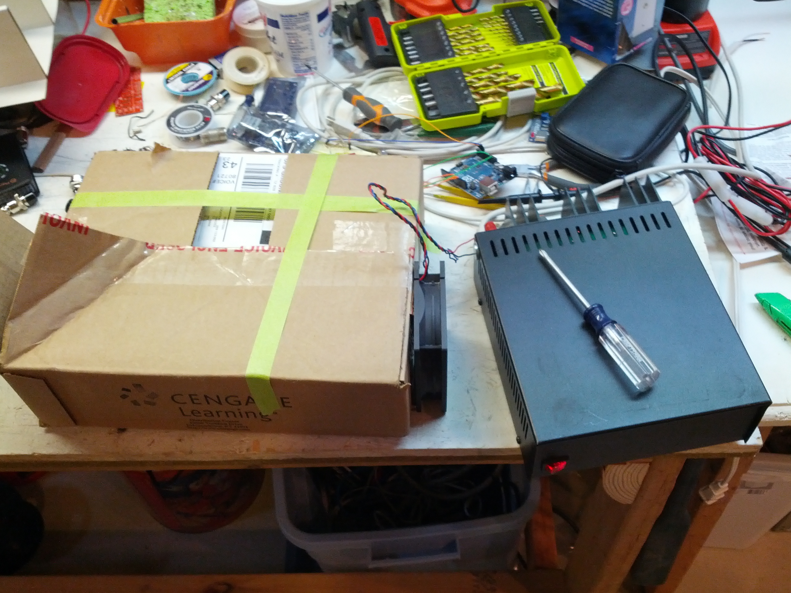
I let the fan run for a while, maybe 12 hours. Yes, I ran it with an expensive linear power supply!
After running it (with this as a small exhaust), I did a smell test over this, and viola! No noticeable smell.
So the exciting conclusion is that this was mounted in my truck on Saturday night, and I got into the truck on Sunday night to actually test the radio (after having it mounted for nearly 24 hours in an enclosed truck in my garage). I detected no smell of smoke in my truck. While nobody was on the local repeater to assist in my test, I had handed one of my HTs to my wife and she gave me a thumbs-up indicating that indeed, the sound was good. Also, I’ve had good sound reports on the morning drive, too.
At any rate, this is one of those “your mileage may vary” situations. I may be right, or I may be lucky. But I’m not smelling smoke!
-73-
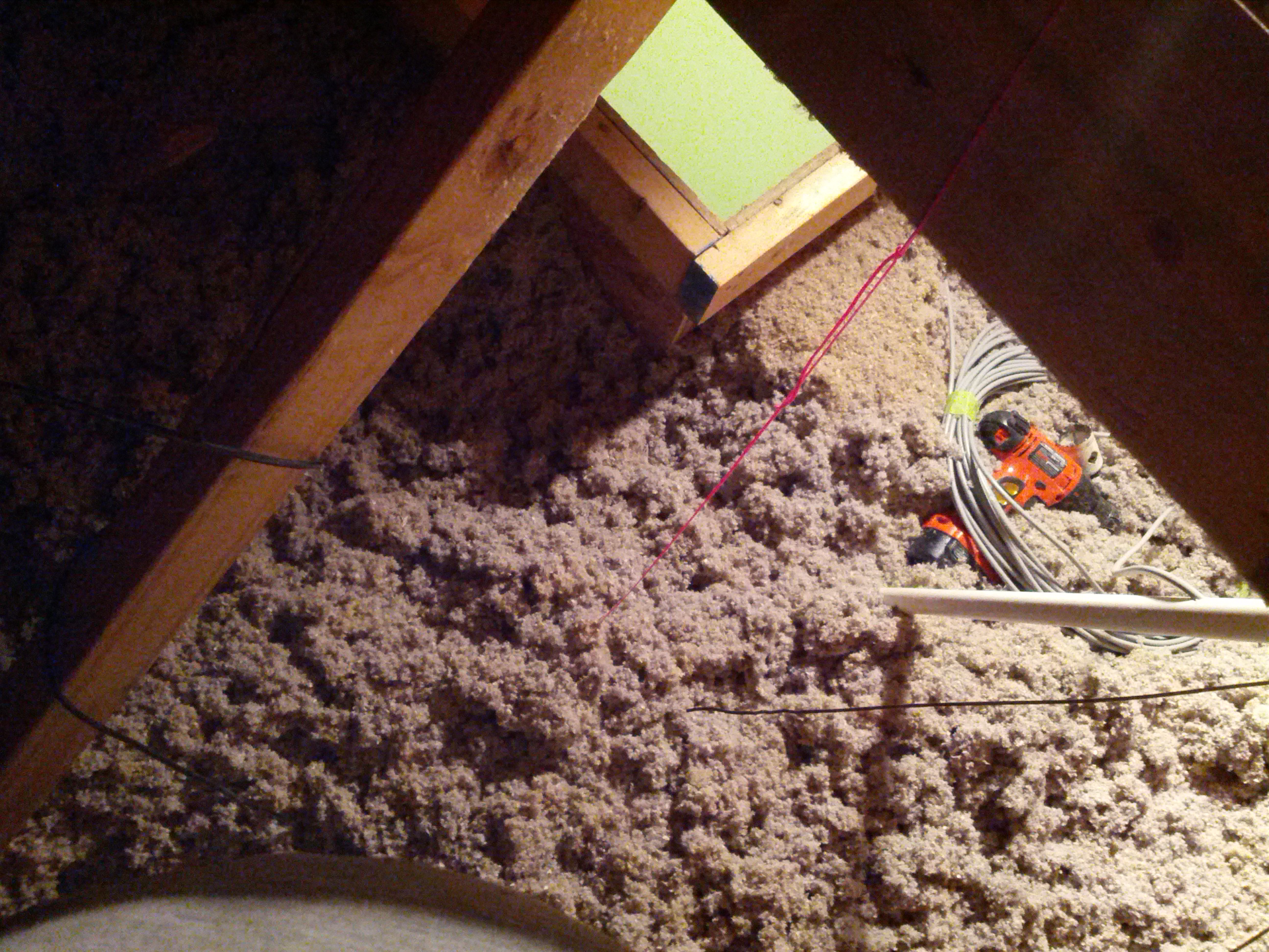
On March 30, I went into my attic to install a few antennas. I learned a few things that bear passing on. Some of these are in pictures, some are text. These are in no particular order. These assume you have cellulose insulation (the type that’s blown in).
- Be ready for a dusty environment. If you don’t wear a dust mask, be prepared to blow black snot out of your nose
- If you wear glasses, make sure they are in no danger of falling off (I almost lost mine, that would have been bad news to drop them into the insulation)
- Make sure you have extra batteries for cordless tools
- Make sure coax is supported at the top. A 20 foot run of coax can be heavy, and you don’t want the line stressed
- Make sure you have a flashlight (as well as an area lamp, like a clip-lamp)
- Take a plastic rake up there with you. Use it to move the insulation around.
A piece of mason’s line (in stylish hot pink) is great to mark where the hole is for coax.
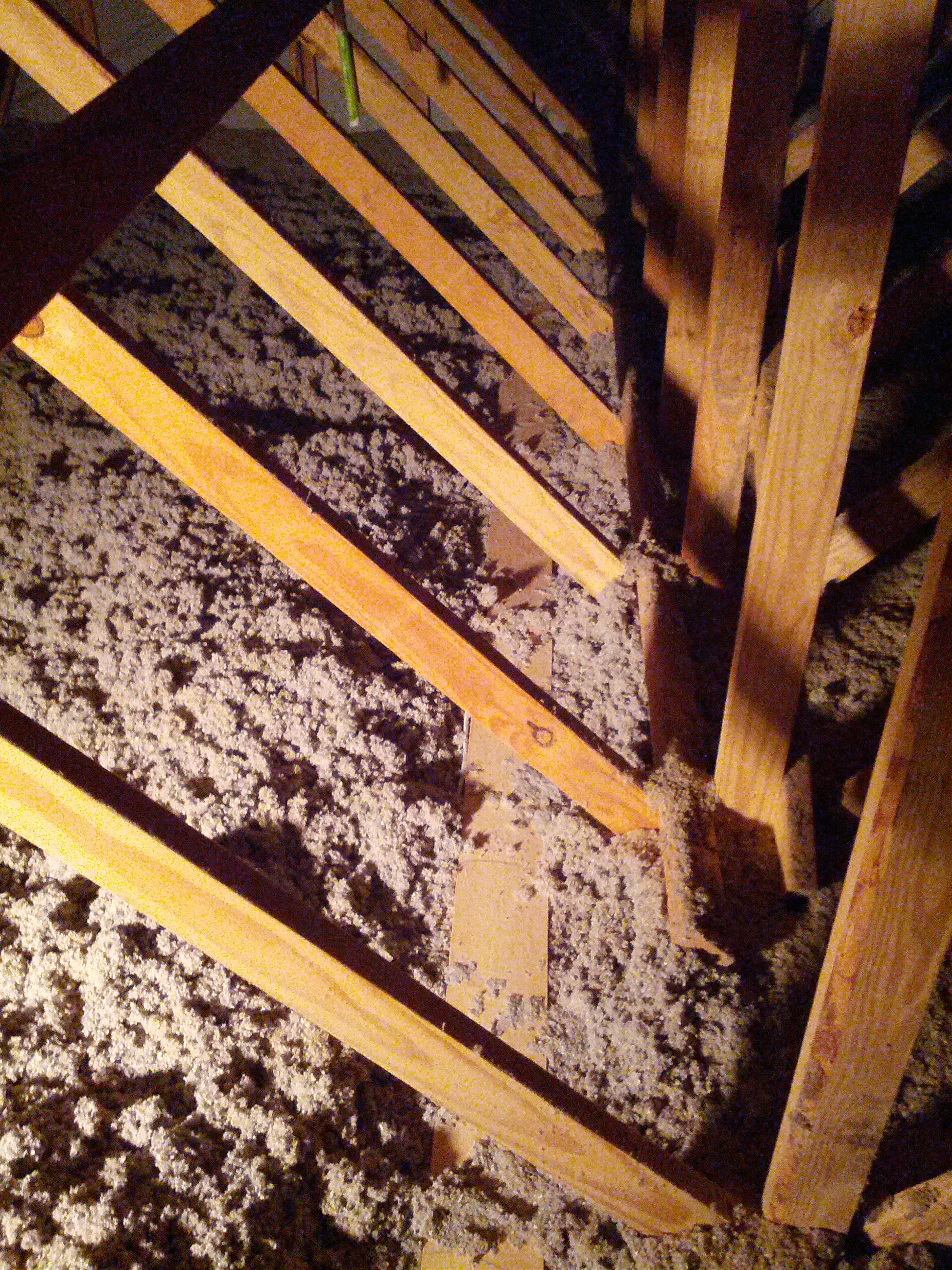
Look for things like a catwalk (like my attic has), just make sure you’re walking on wood and not PVC! Also, don’t expect the catwalk to be on both sides (in mine, it is not).
-73-
After installing my first HF attic dipole and noticing that I can hit Alaska and the Carribean really well and can’t hear New England at all, I decided I want another that is perpendicular to it (then maybe I’ll hit New England and Arizona… and Hawaii!).
I decided to do this antenna a little differently. Consider it an experiment. While I went to a lot of great lengths to put traps in my prior antenna (which shortened it’s length considerably), I decided on this one I want to try window line and see if the interference problem caused by my plasma TV is different. If not, I may be off of 40 and lower until I replace the TV with an LED TV.
Since the window line will be going down along a ventilation shaft that’s pretty large, the one concern I have is that I can’t put metal conduit in the shaft (one thing I wanted to try was to put a grounded metal conduit in the ventilation shaft and see if that fixes the interference problem).
So anyway, the pictures are below.

This is the stress reliever in the center insulator. I drilled three holes in a 3/4″ PVC coupler and used two wire ties to ensure that there isn’t too much stress on the wire joints.

This is the insulator in the center of the dipole. The long wires were soldered to the twin-lead. The PVC coupler allows for me to hang it via mason’s line.

The two sides of the dipole – wires at ~33′ each – are coiled around CLOSED coffee cans, and the window line is coiled. Everything is taped with masking tape so it can be removed easily. The cans have to be closed due the insulation in the attic – open cans would get insulation in them, closed cans do not.
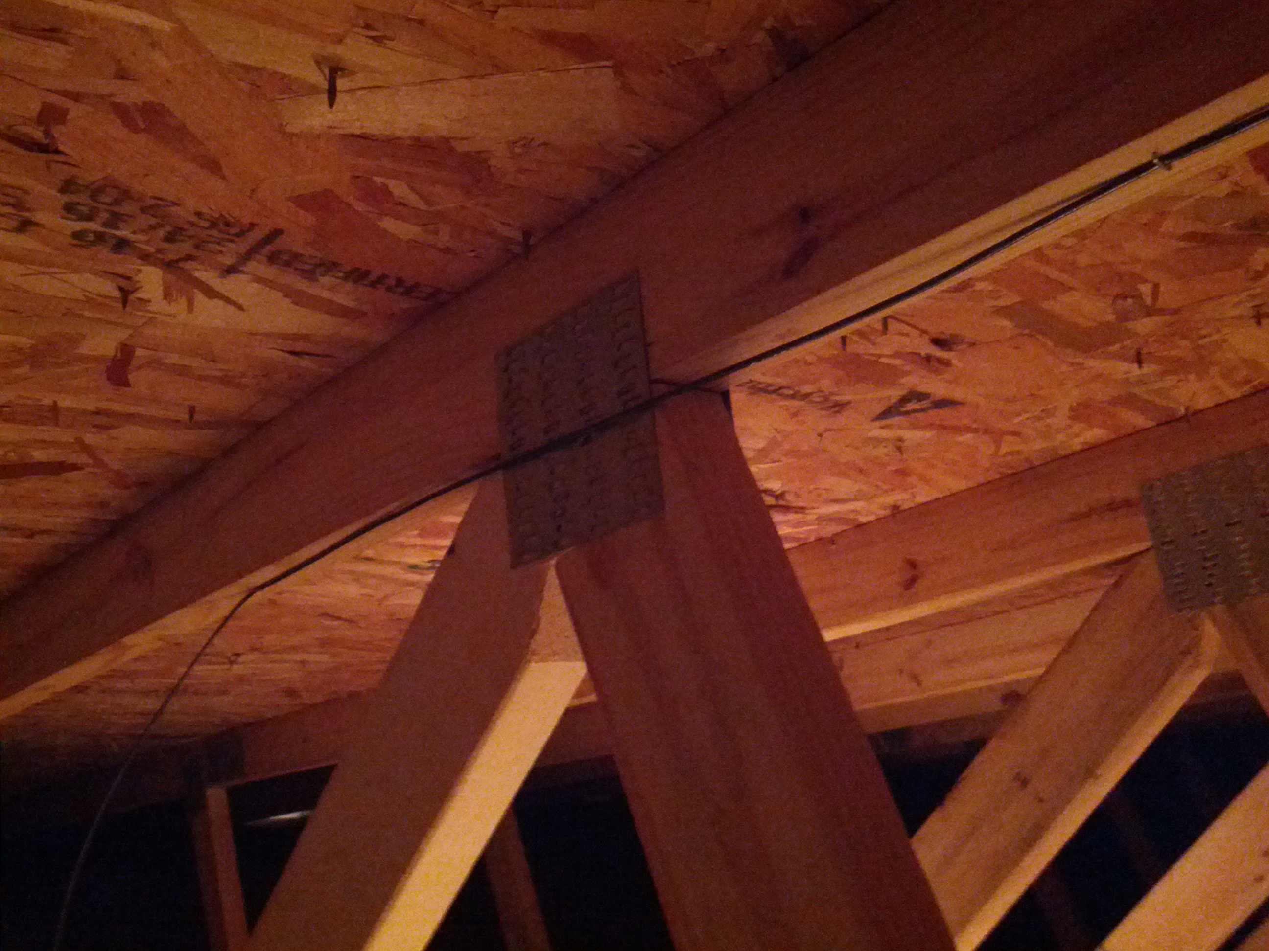
This was the only picture of the installation I could get. Let’s face it, it’s a wire in an attic, it isn’t going to be easy to see nor show anything interesting. Hope that metal plate doesn’t create a problem (there’s one on the other side too, so at least the metal plates will balance out).