
Blog Archives
The finals are replaced and tested! 110 watts out!
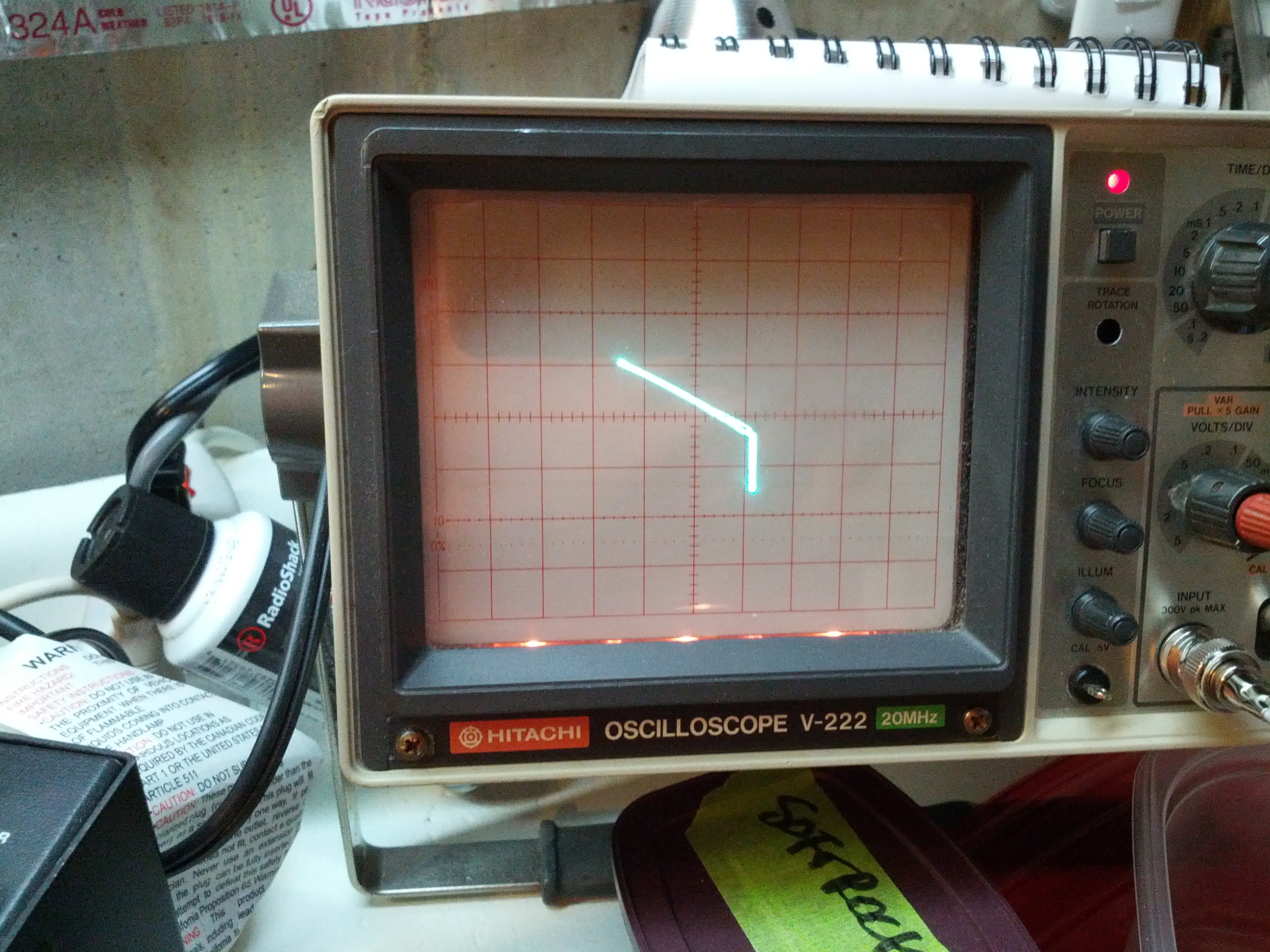
So I started looking over things. One thing I’ve been looking into is the zero beat. It seems to me that when you push the button, it should emit the CW tone. I can get it to emit the tone, but only after pressing the zero beat button many times.
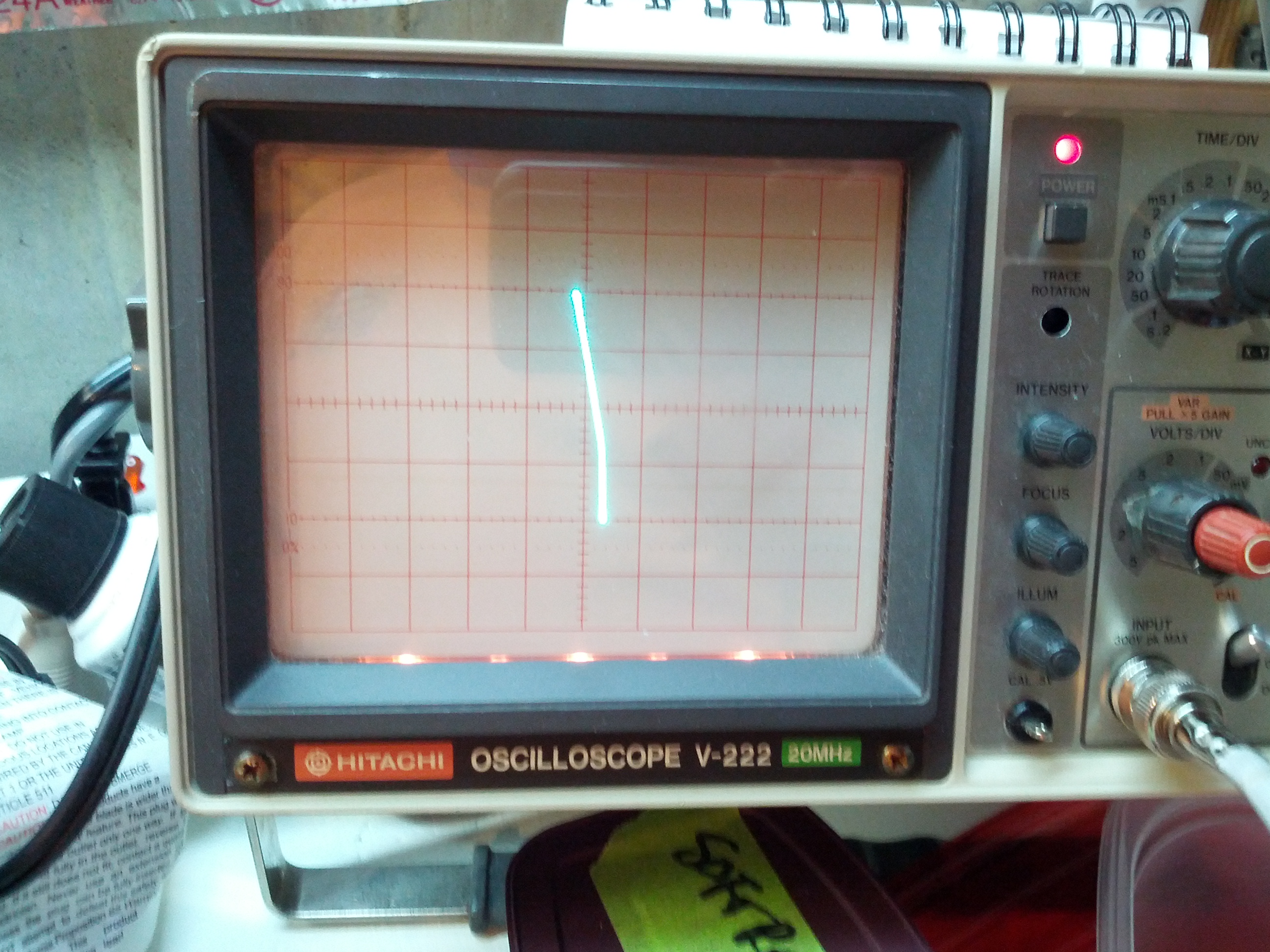
I also don’t like the CW tone. It seems odd even when at the correct frequency. I hooked up the audio output to my oscilloscope and saw the audio output… It looks…er…interesting.
I think I was expecting to see more of a sine wave as opposed to a sawtooth (I guess) wave.
There is one minor little problem – it appears the antenna isn’t properly connected to the receive part of the circuit, because it can’t hear anything. It does transmit on the correct frequency (per my antenna analyzer), so the problem is likely minor as opposed to something going bad related to the frequency or mixer.
This still feels like yesterday’s repair, even though it was tonight when I did all this.
Since I had the final module out from yesterday, I hooked power to it to test. I first tried the driver, and it didn’t trip the circuit breaker. Then I tried the high power amp and it tripped the circuit breaker immediately. Fearing the worst, I embarked on the long process of removing the finals (which was not fun because of how they were stuffed in there.
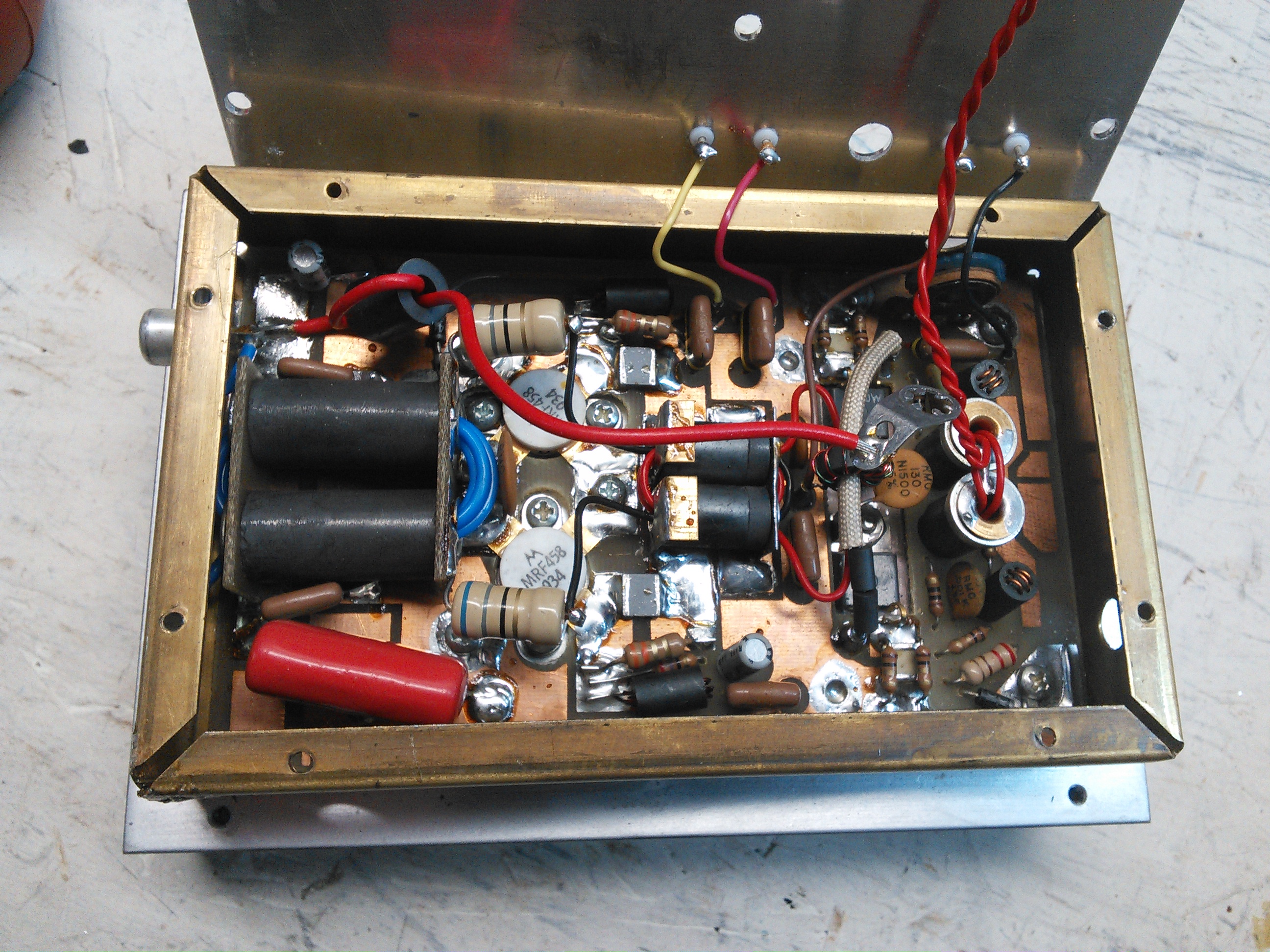
Finals in their copper case. Getting the heatsink off wasn’t too difficult, but getting the circuit board out of the copper was a pain.
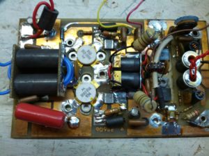
After a lot of work with a heatgun and soldering iron and wick and a bulb, I got this out.
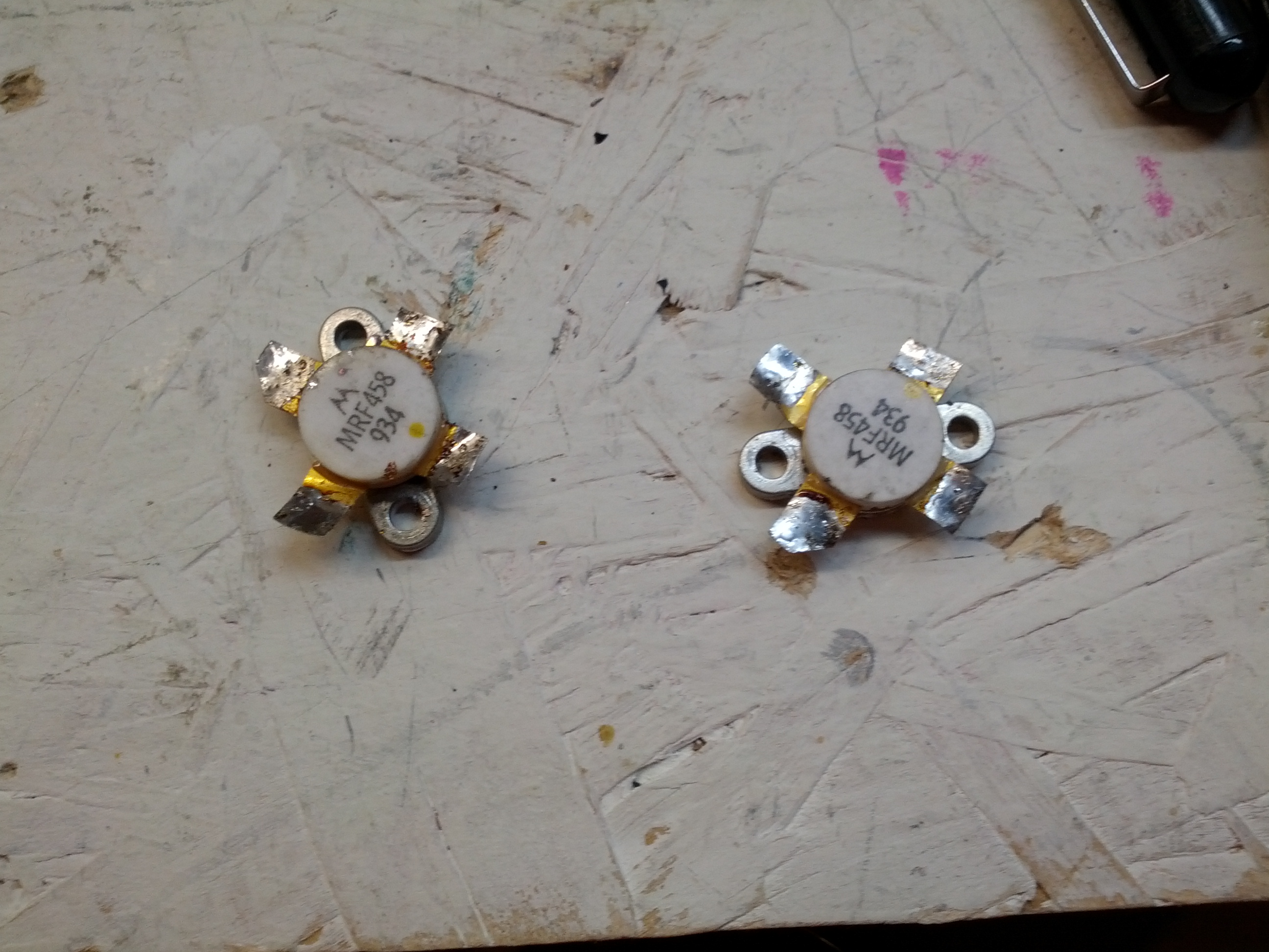
These are the finals after being removed.
So after removing these, I put them on an octopus tester, and tested them. The results are interesting. It also says that one or both of them is likely bad. These things aren’t cheap, but with how much of a pain it is to remove them, the smart thing would be to replace both, since one went, the other is likely not far behind.
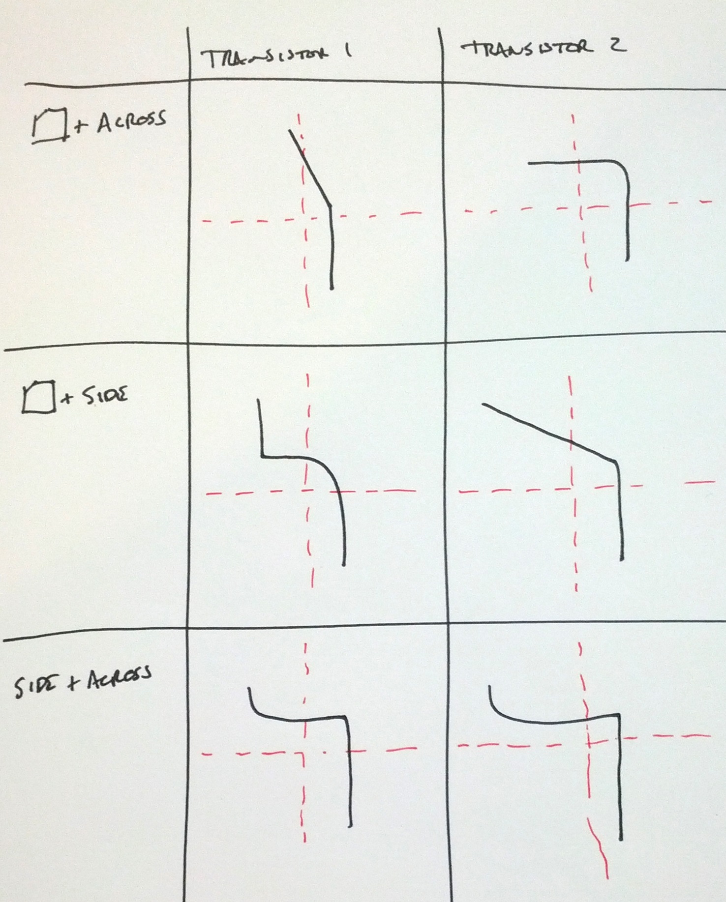
Note: the upper-left and middle-right are nowhere near the same:
Upper Left
Middle right
Next up: replacing the transistors and powering the unit back on!
-73-
So after spending last weekend looking over things, I put everything back EXCEPT the finals and the speaker. I rigged a little power cord with alligator clips (I don’t have another plug for this radio) and a circuit breaker on the hot line. I connected the hot to the fuse in the radio and the ground to the radio chassis and powered up the supply. I was greeted with the radio lighting up 21.2027 MHz. I couldn’t hear anything, as I had the speaker removed.

So the next thing I did was resolder the speaker and the the finals. After finding a nylon washer for the internal hot wire in the finals, I did the minimum replacement of screws and powered the unit back up. It immediately popped the circuit breaker.
Guessing that the finals were bad, I removed the finals and powered the rig back up. The display came back up, but no sound out of the speaker. I started adjusting the volume and RF gain trying to hear something. I then noticed that the mode switch was set to “LOCK”, so the transmitter was on. One thing I did notice is that no power was coming out – I had the internal antenna connection connected to my little QRP dummy load that has a rectifier output and I had my multimeter connected to it and there was no DC voltage coming through the dummy load and no read on the frequency counter in my antenna analyzer.
While there is a slight flaw in my troubleshooting, I’m fairly confident that the problem is the finals and I will be taking a closer look at the module tomorrow.
Incidentally, I looked up the price for new finals at RF Parts. $60 for a pair, and $25 for one. Of that’s the problem, it’ll be a fairly inexpensive fix.
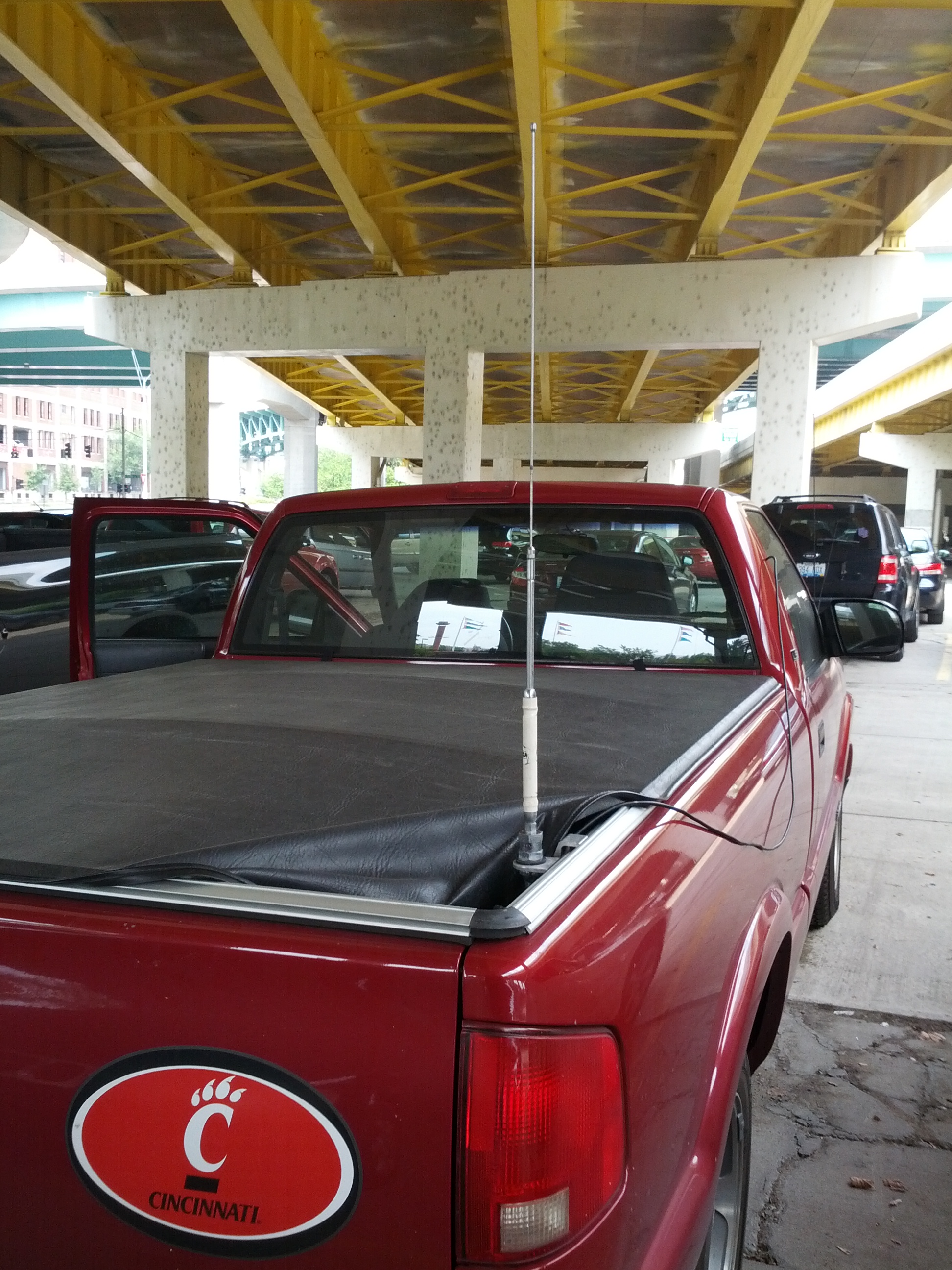
I recently acquired two additional antennas and decided to tune and test them. So I pulled my truck out on the driveway, put the correct ferrite onto the antenna wire, and plugged in the antenna analyzer.
The reason why I saw the SWR go through the roof was because it WAS through the roof. I was able to, with some difficulties, get three of the four antennas tuned. Mind you, tuning these hamsticks is a little bit of voodoo magic mixed with luck and perseverance (in other words, they’re a pain in the ass). The untuned one is 40 meters. The biggest pain was the 6 meter antenna (I had to cut it back because only a few inches of the stinger needed to be out.
There is a problem. I can’t put any of these on my truck and pull into the garage. I do want to move the mount, and once I do that, the 6 meter antenna would be able to stay on the mount, and I’d have to switch others.
See you on HF!
-73-
For those that do know me in real life, I’m not an electrical engineer, I’m a traffic engineer (more specifically, I do traffic forecasting, which also makes me somewhat of a programmer and a transportation planner). I can build electrical things when they’re easy or when there’s a schematic.
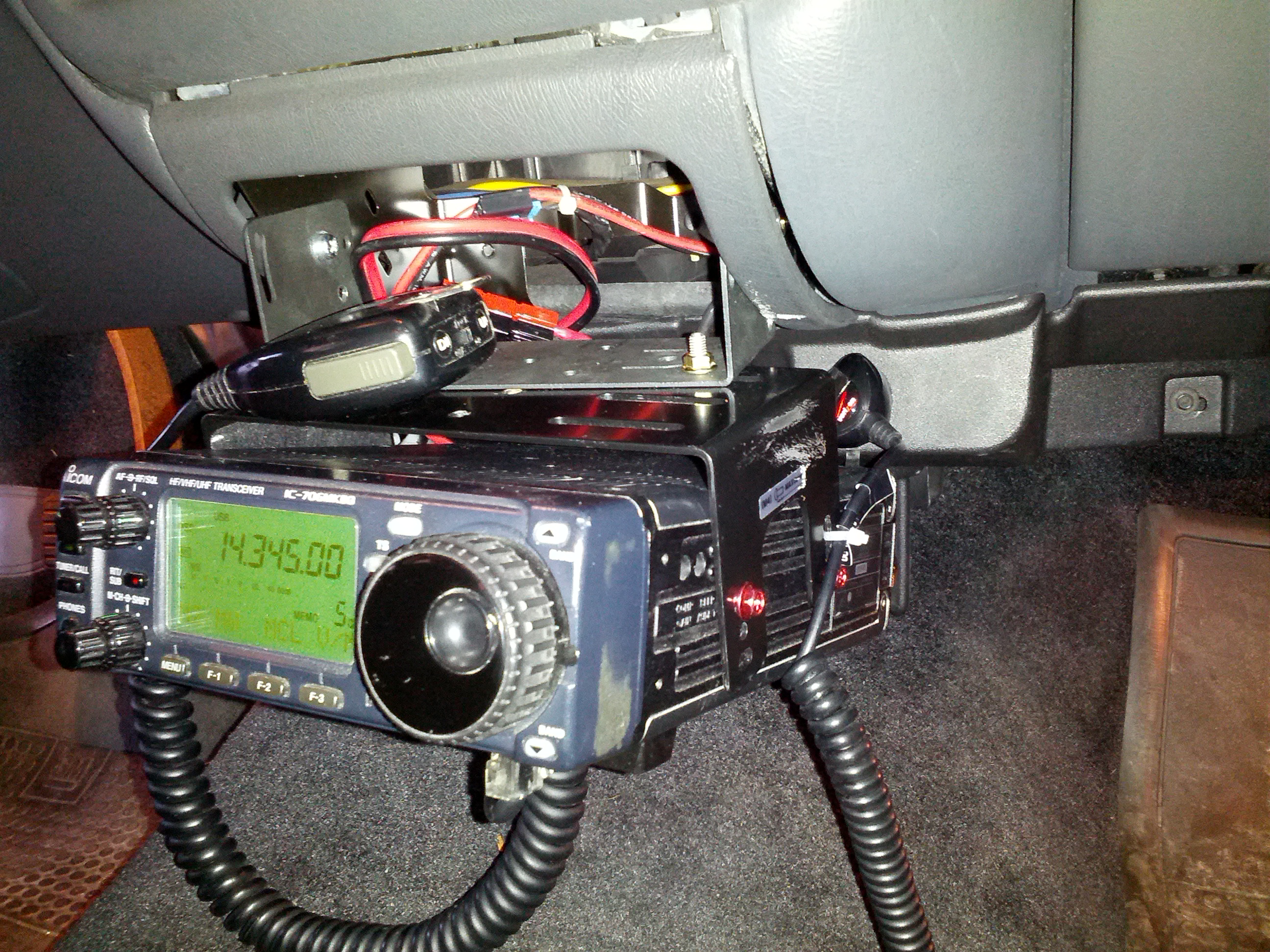
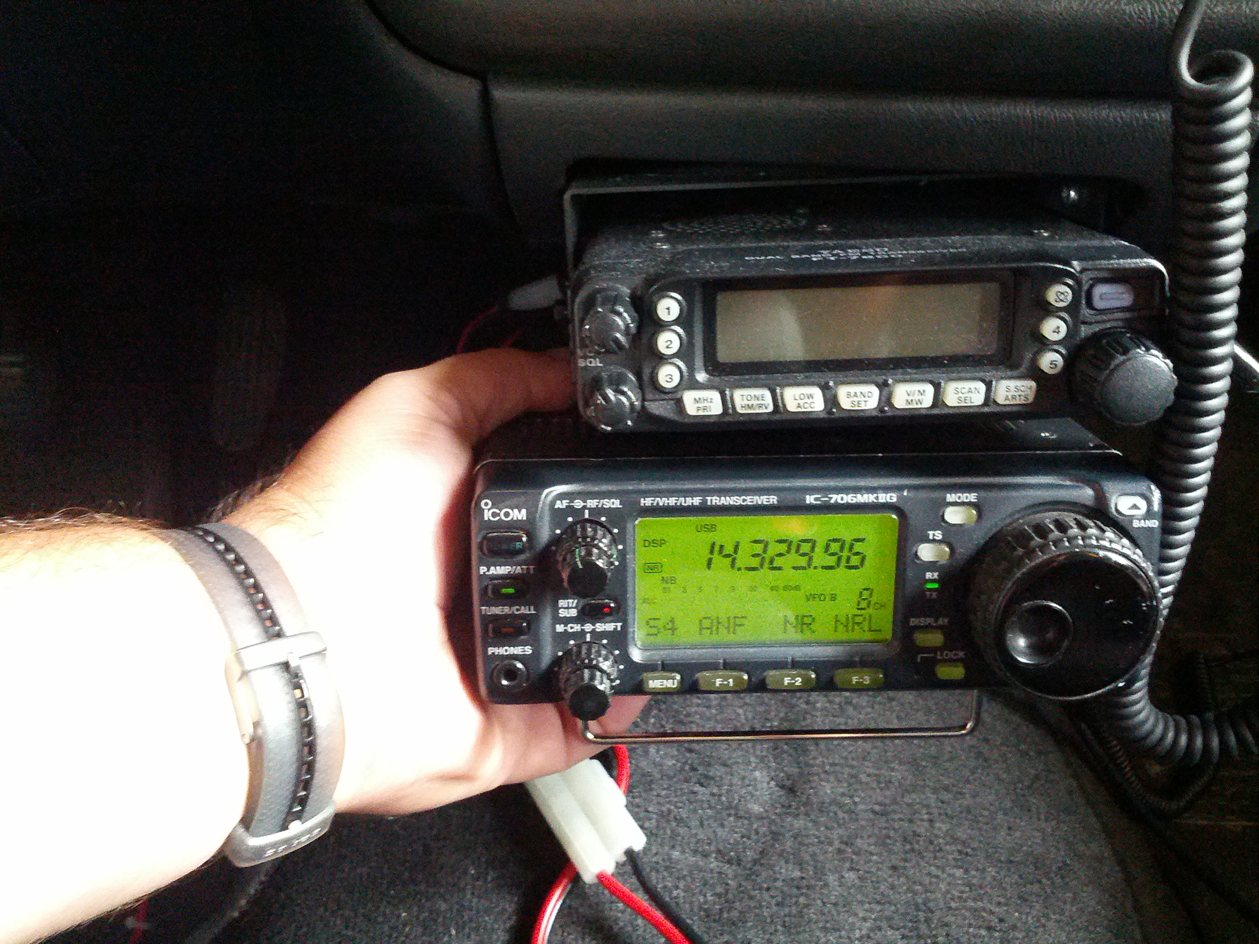
For those that have been following this blog, I just put my only real* HF rig in my truck.
For those of you that have been following me on Twitter and have a damn good memory, you may remember my first rig was a Ten Tec Omni.
So enter my issue. I have a broken (but otherwise great) rig at home, I’m too cheap to send it to Ten Tec**, and I want to learn more about repairing my equipment. This is a lot harder than Arduinos and Raspberry Pis and Beagle Bones!
The Transceiver
The transceiver is a Ten Tec Omni C Model 546. It has all the options – three crystal filters (2.4 KHz, 1.8 KHz, and 500 Hz) and three audio filters (10 KHz, 500 Hz, and 150 Hz of audio) PLUS the WARC band (12 meter and 17 meter) crystals installed.
The guts of the rig are modules – each plugs into the chassis.
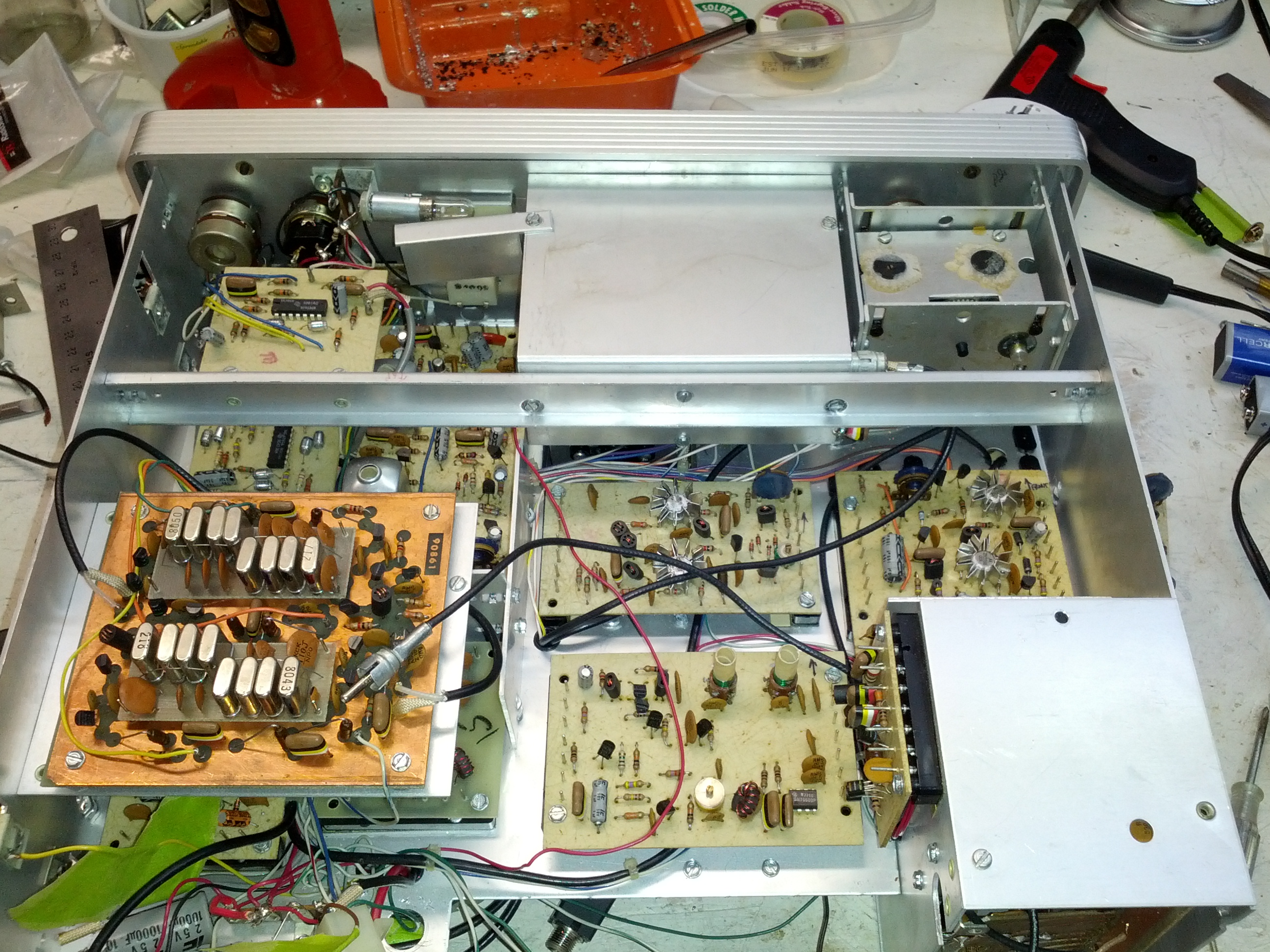
These are the guts of the Omni C. Note the modules, each of these can be removed pretty easily.
The Problem
While running around 25 watts out on the NAQP RTTY contest a few years ago, the rig and power supply died mid-transmission. I tried throwing the switch off then on, and the I saw the lights (the meter and the frequency display) light up and immediately die.
I tested the power supply, and it has 13.8 volts out.
I put an ohmmeter on the rig’s power connectors and saw very low ohms (something like 200 ohms). Seems to me that a part failed and opened a path to ground. With that thought in mind, I did check the 1 uF capacitor and the diode that connect between the +V in and ground (those seemed like the easy tests. I basically disconnected both from ground and tested the resistance betweren +V and GND and there was no change in resistance. However, the rig is modular, and there are dozens of places where there is a capacitor between a +V and GND connection.
My Thoughts
One thing about this rig is that everything is modular. I can remove parts very easily and test the resistance to ground (which I’m guessing should be very high). So if I find something that has a low resistance to ground (in the ohms instead of kilo-ohms), I should probably start looking there.
One thing I did do is remove the meter light bulb and the resistance went up to 450 ohms. It seems to me that the resistance should be somewhere in the 10 kilo-ohm range, but again, I’m not an electrical engineer.
Reader Participation
Let me know in the comments, via twitter, Google+, or email – am I on the right track? Anyone have one of these and know of a common failure? I’ll gather a work-week’s worth of comments and do tests on the weekend (or through the week, if I have the time).
This past Saturday, I went to the Columbus hamfest and ARRL Great Lakes Section Conference. It was a disappointingly small hamfest for being on the NE side of the second-largest city in Ohio (full disclosure: that’s CITY population, regional population puts them third, behind both Cleveland and Cincinnati). I think I spent one hour there and about $40, including admission.
On my way out, I stuck my 10m hamstick on the truck. I knew there was a QSO party on 10, so I thought I’d jump on while driving. I figured I’d check the antenna (which I’ve never tuned). I set the rig to low power and CW and pushed the mic button. SWR was great.
Fearing that such a good SWR for a never-tested antenna was too good to be true and not hearing a CW tone, I set the rig to AM on low power to check. Same SWR reading. So I set the power to 2 (out of 10) and checked again. SWR through the roof. I contemplated going back in to buy another hamstick to get the small Allen wrench to adjust the stick, but decided that spending more money without a full understanding of the issue (and wondering if the problem was tuning or common mode current), I figured I would have been putting good money after bad and decided to leave and just listen on 10 on my way home until I got in the area of the repeater.
When I returned home (well, several hours after I returned home), I did a little bit of reading on the mobile HF oracle (k0bg’s website) and it confirmed my common mode suspicions. Looks like I need to get an order in for some mix 31 ferrite beads. I need to do some vehicle maintenance, so I may try to do all of it next weekend.
Additionally, I spoke with another local ham on the following Monday that gave me a few pointers courtesy of a friend with a 706, including to put a ferrite on the power leads and to make sure the bonding is done well – he had to strip paint to get a good bond.
So in the immortal words of K5PO from the Noise Blankers (who ironically has an Icom right in front of him and his name is eerily similar to mine)…

-73-
I gave a presentation to the Oh-Ky-In Amateur Radio Society on August 6, 2013. This was an update of the presentation I gave to the Cincinnati FM Club in February, which was an update of the presentation I gave to the Milford Amateur Radio Club a while back. This page is a set of links for those that attended or missed the presentation.
Presentation: Introduction_to_Arduino_Microcontrollers (PDF warning)
Links Mentioned:
QRPTracker (satellite tracker)
Starter Sets:
Sparkfun: New Starter Set (with Arduino Clone, $50), New Inventor’s Kit ($100), Starter kit ($60)
Adafruit: Starter Pack ($65), Starter Kit ($125)
(added 2013-08-22) Seeed Studio: Starter Set ($70), Starter Kit (bigger) ($120)
Add-On Packs:
Have an Arduino board but not enough accessories or don’t know where to get started? Seeed Studio has a “Sidekick Basic Kit” that can get you up and running – it doesn’t have an Arduino, but it has a lot of components (etc) to get you started. And it’s $20. Seeed Sidekick Basic Kit ($20)
NOTE: Look hard at what these packs include! There ARE differences.
Raspberry Pis and Beagleboard Blacks can be bought at Mouser, Digikey, and Newark Electronics/Element 14. Raspberry Pi accessories (like the Pi Plate an Pi Cobbler) can be bought at Adafruit or Newark Electronics/Element 14.
After reading Russ’s comment on last week’s post, I decided that he’s right. There’s no good reason to keep the FT-7800 in the truck when I’m installing a better, more capable radio. So it came out. Below are the gory details, all in pictures.
This is the reason why people like K0BG says on his website (which is the Oracle of Mobile HF) to NOT use cigarrette lighter wires – these things are around 16 gauge. Pulling 20 amps through this for an extended period of time would cause a fire.
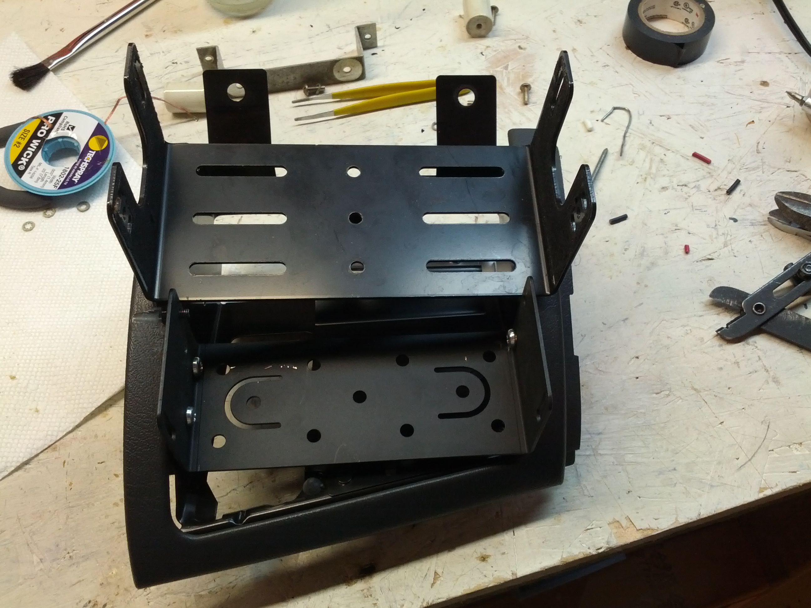
There’s a little problem with fitting this thing in…
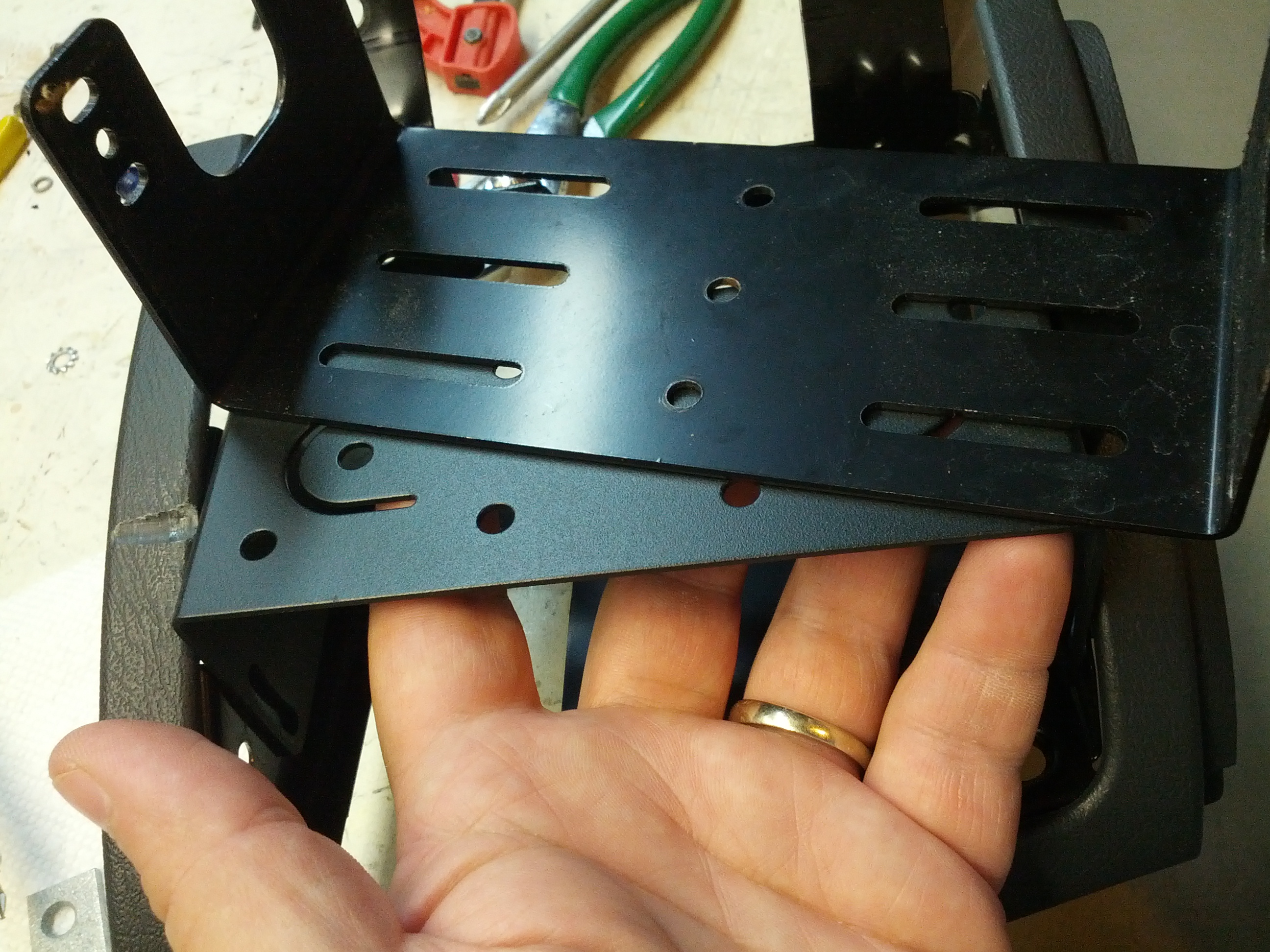
So if I turn this over and bolt it in upside-down…
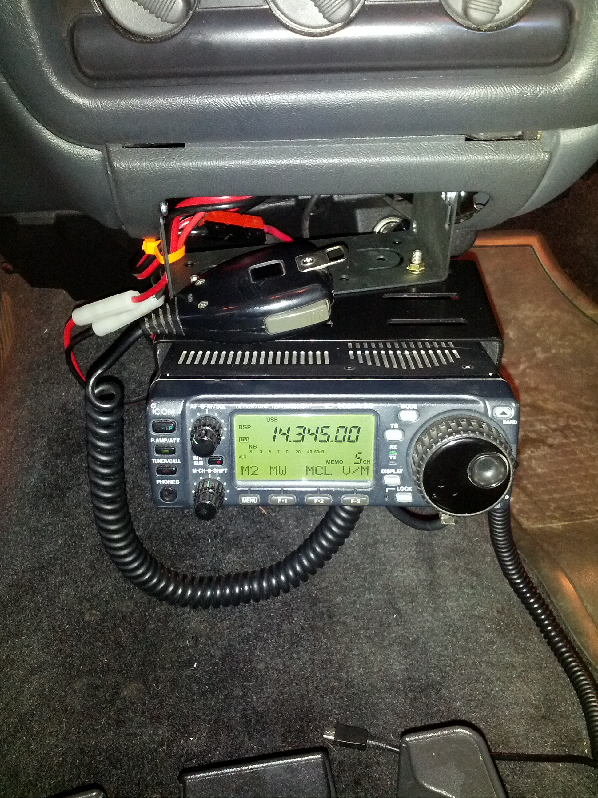
It’s in and that’s that!
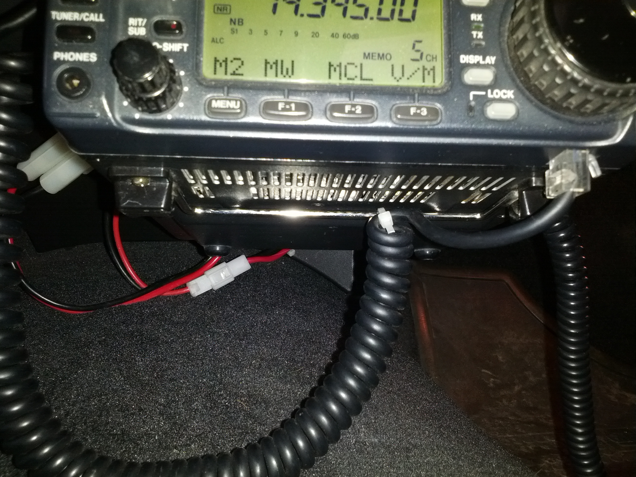
I zip-tied the mic cable to the foot on the bottom of the rig to keep from pulling too hard on the cable and damaging it. The modular cable ends are a pain to replace because the mic wire bundle is not really made for those (unlike network cable which is simple to terminate).
I also zip-tied my cellphone charger to the mount to keep the plug from pulling out (which I wouldn’t be able to fix while driving, obviously).
With all that said and done, all that remains is dealing with the antenna side of the equation, and removing the one below, which certainly feels like a dummy load… on a stick.
Someone gave this to me. I’m considering giving it back once I have a better alternative.
Last Friday while sitting in the parking lot of my building, I tried contacting NR4CB or AB4UG to wish them a happy wedding day. It didn’t happen. I could barely hear Connie, could tell someone was there (but couldn’t make out the words) when Eugene was on. It didn’t help that other stations were 2 kHz above and 2 kHz below.
I got to thinking about running mobile HF again.
This could work.
It looks like I need to fashion a pair of brackets – one would be simple, and the other complex a little. I do have the mobile bracket for my 706, so I can always use that as a guide for holes.

It seems far simpler when it is a sketch on a post-it note than when it is a piece of sheet metal that has to fit.
Another thought with the brackets is that I don’t *have* to have the radio there. I need the head there, but I do have the head separation kit, so I can always put the radio elsewhere and run power and antenna to it.
The other thing I looked at was the antenna. Like every other self-respecting ham, I feel as if antennas should be big. I was concerned about this 20m antenna and a quick look at K0BG’s website confirmed my suspicions.
Someone gave this to me. I’m considering giving it back once I have a better alternative.
The antenna is so small compared to 5 meters (roughly a 1/4λ for 20 meters) that it has to be basically a dummy load on a stick. I’m not sure if the bridge above me helped or hurt; I had thought about driving up to Mt. Adams, but for various reasons I couldn’t stray too far. I’ll have to try again. I need to run the antenna wire (I’m not sure other vehicles would like the idea of me having that coax flapping around, and I can’t have the tonneau cover open like it is when I’m stationary.
The last consideration is power, but it isn’t a huge consideration. I have a power line that is safe for 20 amps (as much as my 706 needs), but I don’t want to have to unhook/rehook power connectors (those ARE live, after all). I’m thinking I need a miniature power distribution center with two pair of fused power poles and a master switch, and maybe a battery shutoff.
-73-
In Part 1 of this, I went over the setup of ThingSpeak and several associated and almost-associated packages.
This part will be more about the funner stuff.
Rain Gauge Reader
The first thing I had to do was build a rain gauge reader. I ultimately started that before doing part one, but then moved on to a standalone node.js program that counted clicks from the rain gauge.
The rain gauge is a tipping-bucket rain gauge that tips when the rain gets to 0.2mm. The guts are in the picture below.
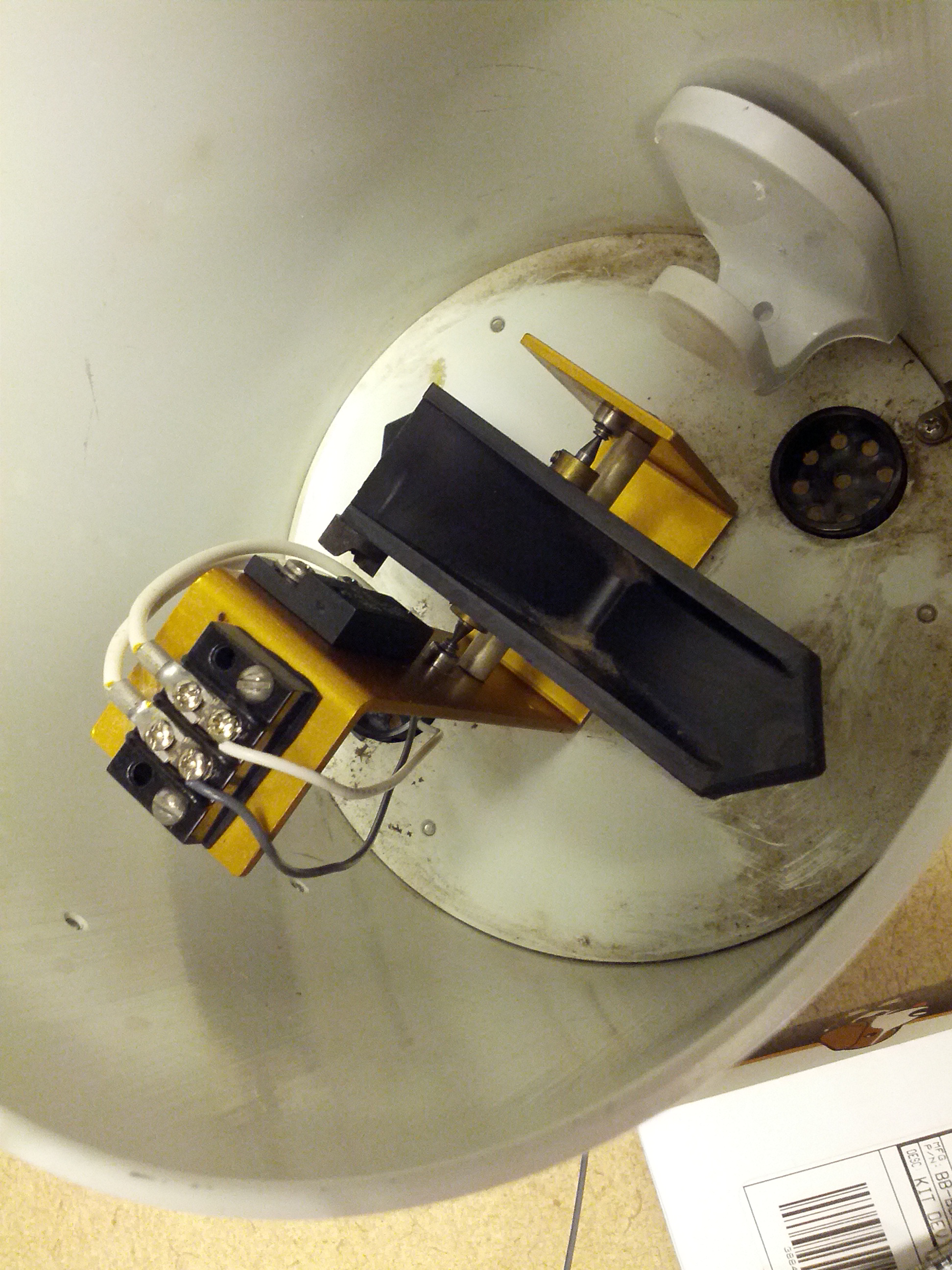
These are the guts of the rain gauge. You can see the tipping bucket (black) and the barrier terminal that connects to the switch. Yep, that’s all it is, a switch.
The rain gauge initially came with a little board that has a PIC and an EEPROM that stored clicks. I didn’t care for that idea, since the ultimate plan is to see if we can put this on our building’s roof with a battery and a solar panel.
This is where the BBB comes in. I connected the rain gauge to the BBB and started playing with node.js until I came up with the program in the gist below.
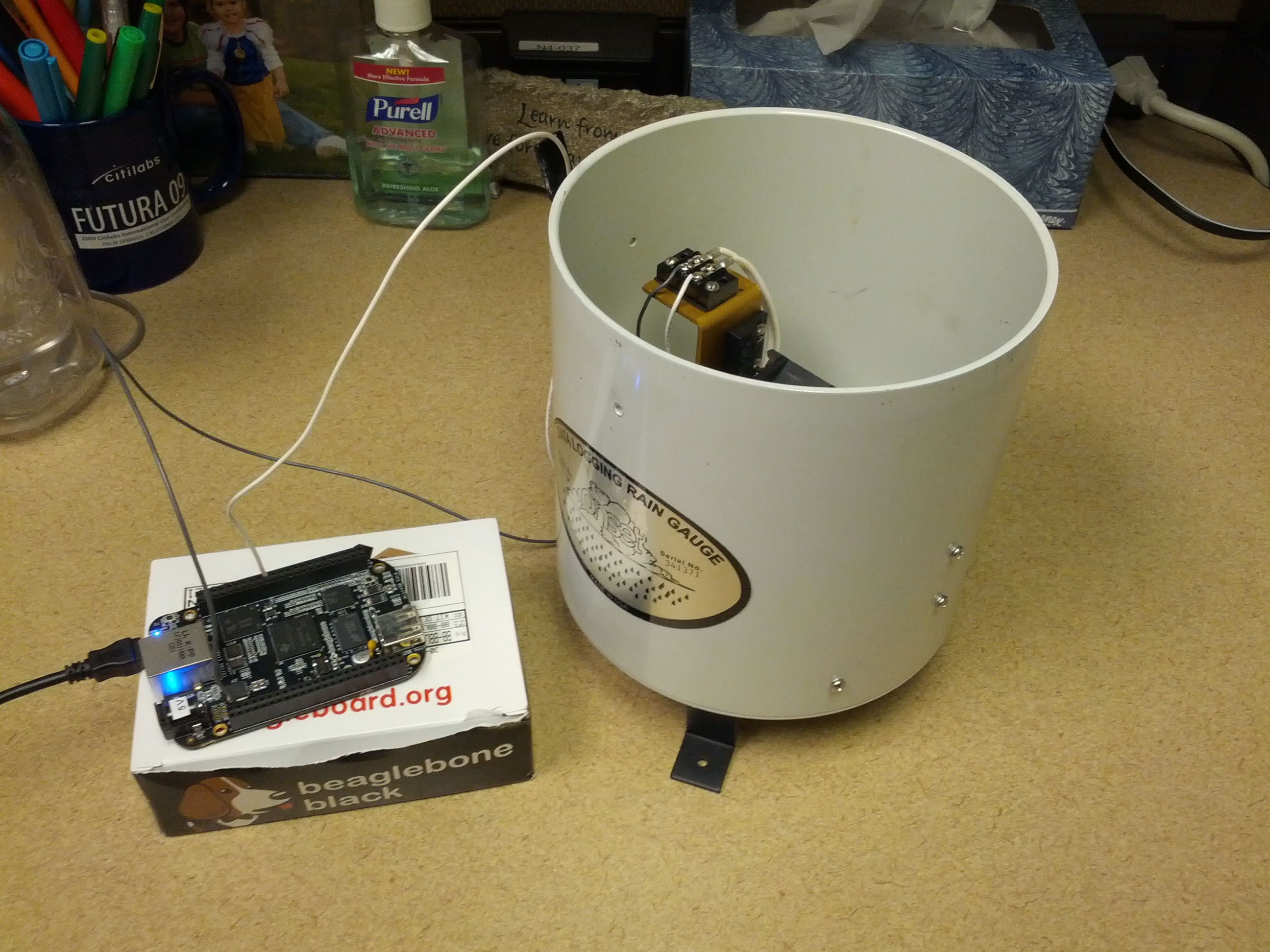
Beaglebone Black connected to the rain gauge. I routed the wires through the drain of the rain gauge, which may change when I actually put this in use.
After setting it up, it was time to test.
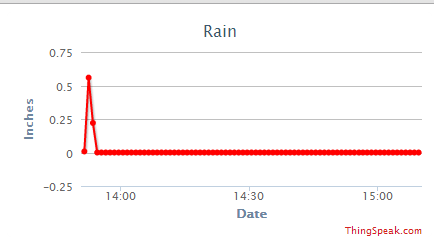
Wow, it rained for a half inch during a minute in my office!
The third part of this will be making this fault-tolerant: fixing the time issue (it doesn’t keep time), starting things during startup, and security.
-73-